
K-WANG


KUKA KR C4 compact robot controller
KUKA KR C4 compact robot controller
The technical specification manual for KUKA KR C4 compact robot controller is aimed at professional users with advanced knowledge of electrical and electronic systems, robot controllers, and Windows systems. It clearly states that it is only intended for operating KUKA industrial robots and prohibits misuse scenarios such as climbing and hyperparameter operation. The document covers in detail the product composition (control box, drive box, smartPAD, etc.), key technical parameters (maximum 6-axis, protection level IP20, power supply 200-230V AC, weight 33kg), safety specifications (operating mode, emergency stop device, safety level PL d), planning and installation, transportation, start-up and commissioning, service support, etc. It emphasizes the need to strictly follow safety processes and standards to ensure equipment operation safety and personnel protection.
Product Core Information
composition structure
Industrial robot: composed of manipulator, robot controller, smartPAD teaching pendant, connecting cable, software, and optional accessories
Robot controller: divided into control box and drive box, can be installed on a 19 "rack or placed independently, and the core components include:
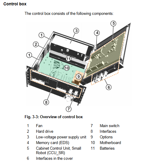
Control box: Control PC (including 3 motherboard models D3076-K/D3236-K/D3445-K), Cabinet Control Unit Small Robot (CCU_SR), low-voltage power supply unit, battery, power filter, fan, etc
Drive box: KUKA Power Pack Small Robot(KPP_SR)、KUKA Servo Pack Small Robot(KSP_SR)、 Motor connector X20, braking resistor, fan, etc
Key component description
Control PC: responsible for graphical interface, program creation, path planning, driver control, etc., supporting multiple expansion cards (fieldbus cards, dual network cards, etc.)
CCU_SR: Core distribution and communication interface, including CIB_SR (interface board) and PMB_SR (power management board), supporting functions such as safety I/O and contactor activation
SmartPAD: Teaching pendant, 8.4 "touch color screen (600x800 pixels), protection level IP54, weight 1.1kg, including 3 enable switches
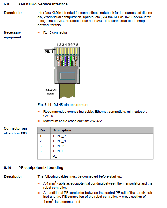
Interfaces: including security interface X11, Ethernet security interface X66, EtherCAT interface X65, service interface X69, etc. X11 and X66 cannot be used simultaneously
Technical data
Category key parameters
Maximum number of axes for basic parameters: 6 axes; Protection level: IP20; Weight: 33kg; Sound Level: Average 54 dB (A)
Power supply requirement rated voltage: 200-230V AC (single-phase/two-phase, with grounded neutral wire); Frequency: 50Hz ± 1Hz or 60Hz ± 1Hz; Rated power: 2kVA; Fuse: 2x16A slow melting
Operating temperature under environmental conditions:+5~+45 ℃ (278~318K); Storage temperature (with battery): -25~+40 ℃; Humidity: 3k3 level (no condensation); Altitude: ≤ 1000m (no capacity reduction), 1000-3000m (5% capacity reduction per 1000m)
Size and installation compatible with 19 "rack (depth ≥ 700mm); 70mm of heat dissipation space needs to be reserved on both sides; Can be installed horizontally or vertically
Cable requirements for smartPAD cable: standard length+2 extensions, total length ≤ 50m; cable length difference for each channel of RDC box ≤ 10m
Safety regulations
core principle
Intended use: Only for operating KUKA industrial robots, prohibited for misuse scenarios such as climbing tools, hyperparameter operation, and use in explosive environments
Compliance standards: comply with EC Machinery Directive (2006/42/EU), EMC Directive (2014/30/EU), EN ISO 13849-1 (PL d/Category 3), etc
Personnel Requirements
Operators need to have advanced knowledge of electrical and electronic systems, robot controllers, and Windows systems. It is recommended to attend KUKA College training
The system integrator is responsible for equipment installation, risk assessment, and compliance declaration; Maintenance and debugging need to be carried out by professional training personnel
Key safety functions
Operation modes: T1 (manual low speed ≤ 250mm/s), T2 (manual high speed), AUT (automatic), AUT EXT (external automatic)
Safety devices: local/external emergency stop button, dual circuit enable switch (3-speed: not pressed/neutral/emergency), safety door interlock, software limit switch, mechanical terminal block
Stop category: Safety STOP 0 (immediate stop), Safety STOP 1 (path keeping stop), Safety STOP 2 (normal deceleration stop)
Scene security measures
Transportation: The controller needs to be transported horizontally to avoid vibration and impact; The robotic arm needs to be placed in the designated transportation position according to regulations
Startup: Wiring, safety devices, and temperature adaptation (to avoid condensation) need to be checked. The new program needs to be tested in T1 mode first
Maintenance/Repair: Power off and lock, post warning labels, wait after power off (some components have residual voltage of 50-780V), and prohibit live operation of high-voltage components
Operation and Startup
Planning and Installation
Installation conditions: 19 "rack depth ≥ 700mm, with 70mm of reserved heat dissipation space on both sides; Only supports grounded neutral wire power supply system
Equipotential connection: A 4mm ² cable (between the controller and the robotic arm) and an additional PE conductor (between the power supply cabinet and the controller) need to be connected
Core Steps for Startup and Debugging
Check for transportation damage to the controller and install and fix it (horizontal/vertical)
Connect motor cable (X20), data cable (X21), smartPAD (X19)
Complete equipotential connection and power connection
Release battery discharge protection (insert X305 connector)
Configure and connect X11 interface (safety circuit)
Release the smartPAD emergency stop button, turn on the main switch, and start the system
- YOKOGAWA
- Reliance
- ADVANCED
- SEW
- ProSoft
- WATLOW
- Kongsberg
- FANUC
- VSD
- DCS
- PLC
- man-machine
- Covid-19
- Energy and Gender
- Energy Access
- Renewable Integration
- Energy Subsidies
- Energy and Water
- Net zero emission
- Energy Security
- Critical Minerals
- A-B
- petroleum
- Mine scale
- Sewage treatment
- cement
- architecture
- Industrial information
- New energy
- Automobile market
- electricity
- Construction site
- HIMA
- ABB
- Rockwell
- Schneider Modicon
- Siemens
- xYCOM
- Yaskawa
- Woodward
- BOSCH Rexroth
- MOOG
- General Electric
- American NI
- Rolls-Royce
- CTI
- Honeywell
- EMERSON
- MAN
- GE
- TRICONEX
- Control Wave
- ALSTOM
- AMAT
- STUDER
- KONGSBERG
- MOTOROLA
- DANAHER MOTION
- Bentley
- Galil
- EATON
- MOLEX
- Triconex
- DEIF
- B&W
- ZYGO
- Aerotech
- DANFOSS
- KOLLMORGEN
- Beijer
- Endress+Hauser
- schneider
- Foxboro
- KB
- REXROTH
- YAMAHA
- Johnson
- Westinghouse
- WAGO
- TOSHIBA
- TEKTRONIX
- BENDER
- BMCM
- SMC
- HITACHI
- HIRSCHMANN
- XP POWER
- Baldor
- Meggitt
- SHINKAWA
- Other Brands
- UniOP
- KUKA
- IBA
- Beckhoff
- ADLINK
-
Beckhoff CX1100-0910 - Power Supply Module
-
Beckhoff C5210-0010 - Communication Module C5210
-
BECKHOFF KL1352 - Bus Terminal SET OF 2 FREE FAST SHIP
-
Beckhoff EL3058 - 8 x analog input single ended 4...20mA 85惟 shunt 12bit
-
Beckoff CX1100-0920 - UPS Module 24VDC (US SELLER) * *
-
BECKHOFF C6920-0000 - C69200000 PLC Moudule
-
Beckhoff CX5120-0115 - CPU controller module CX5120-0115
-
Unknown 15F5C1E-Y50A - Of Frequency Converters
-
Beckhoff AX5118-0000-0200 - Servo Drive HTP0
-
BECKHOFF AX5106-0000-0200 - Servo Drive
-
Beckhoff CX5240-0175 - Module (free) #U2327D YG
-
Beckhoff CP6607-0001-0000 - Compact PC Panel Economy Installation Operator 5,7 "
-
Beckhoff EP3744-0041 - 2022 EP37440041 Module
-
Beckhoff CP6209-0001-0020 - 6.5" PC Touch Screen Control Panel 24VDC
-
Beckhoff CX9020-0111 - /U900 +8x+2xEL3121+1x EL9410+3xEL1008+1x EL2008 Set
-
Beckhoff C6525-1030-0050 - Industrial PC
-
Beckoff CX1100-0920 - UPS Module 24VDC (US SELLER)
-
Beckhoff CX5010-0120 - CX5010 Processor Intel Atom Z510 B24
-
Siemens 6FC5203-0AF04-1BA1 - Operation Panel
-
Beckhoff CX5230-0175 - / 000029724 Embedded PC / Industrial PC on Rail
-
Beckhoff CP3916-0000 - industrielles Anzeige- und Bedienterminal
-
BECKHOFF CX1500-M310 - CX1000-N000 CX1000-0011 CX1000-C00L CX1100-0002 PLC Module
-
Beckhoff EL1872 - 16-channel digital input terminal
-
BECKHOFF EP2318-0001 - module
-
Beckhoff CX9020-0110 - Basic CPU Module
-
Beckhoff EL2564 - EtherCAT Terminal, 4-channel LED output, 5鈥?8VDC, 4A, RGBW
-
Beckhoff CX5130-0155 - /000105637 Automation Embedded PC
-
B&R 400 - Power Control Panel Rev D0 24 VDC
-
Beckhoff CX2020-0155 - module
-
Beckhoff CX9020-0115 - PLC Module
-
BECKHOFF EL6695 - PLC EL 6695
-
BECKHOFF EL7047 - PLC Modules
-
Beckhoff CX1000-0012 - Control HW 2.2 + CX1500-M310 + CX1000-C00L + CX1100-0002+
-
Beckhoff C6920-1039-0030 - control cabinet industrial PC CPU Celeron 1.90 GHz, 2 cores
-
BECKHOFF CX1100-0910 - PLC Module#
-
Beckhoff IL2301-B318-0000 - Coupler Box 4 Channel Digital Input |
-
Beckhoff CX7080 - Module
-
Beckhoff C6930-0060 - Industrial PC
-
Beckhoff CP7902-1060-0000 - Touchscreen 15 " CP7902
-
beckhoff CX9020-0111 - Controller module or UPS
-
Beckhoff CX8091 - PLC Module CX8091
-
Beckhoff C6640-1008-0030 - Control Cabinet Industrial PC
-
BECKHOFF CX1100-0920 - module
-
Beckhoff C9900-M921 - see pictures
-
BECKHOFF CP6829-0001-0000 - Touch Panel
-
BECKHOFF C6930-0060 - Industrial Computer
-
BECKHOFF CX8050 - PLC module
-
Beckhoff CP6202-0021-0020 - Touch Screen #
-
BECKHOFF AM3031-0C20-0000 - SERVO MOTOR
-
Unknown BCH1302N11A1C - Servo motor
-
Beckhoff EL2502 - 2-channel pulse width output terminal
-
Beckhoff EL6731 - Profibus Master / *Rev: 0025
-
Beckhoff CP3918-0010 - Control Panel
-
BECKHOFF CP2915-0010 - [24 MONTH WARRANTY] Control Panel
-
Beckhoff AX5203-0000-0202 - Servo Drive
-
Schneider TSXDSY64T2K - PLC OUTPUT MODULE
-
Beckhoff EP4174-0002 - Module-
-
Beckhoff IL2302-B318-0000 - Profibus Box
-
Beckhoff CP6709-0001-0000 - Touchpanel
-
BECKHOFF CX2030-0123 - Controller
-
Beckhoff CX9020-0111 - Processor Module
-
Beckhoff CX1020-0000 - CX Basic CPU Module
-
Beckhoff AX2003-AS - Servo Drive HTP0
-
Beckhoff C6240-1052-0040 - 4-086-06-3073 Industrial Computer CB1052-0003
-
Beckhoff EL1918 - 8 xTwinSAFE Input
-
Beckhoff AM8072-0R20-0000 - Servomotor
-
BECKHOFF AM8021-1B21-0000 - servo motor #T882 YS
-
Beckhoff EL6224 - 4 X Terminal IO-LINK
-
Beckhoff CX5140-0135 - embedded PC with Intel Atom processor 4 GB HW 3.6
-
Beckhoff CP7201-1000-0000 - Panel PC #
-
Beckhoff CX5130-0121 - Embedded-PC 4GB CPU Module HW 2.5 Industrial PC
-
Beckhoff AM8022-0D41-1002 - Servomotor
-
BECKHOFF CX2030-0130 - Module
-
BECKHOFF EL1872 - 16-channel digital input terminal
-
Unknown GXMMW.A203P33 - 1pc encoder
-
Beckhoff EL6631-0000 - EtherCAT Terminal 2-Port EL 6631
-
BECKHOFF C6925-0030 - Industrial Computer
-
Beckhoff CX8190 - A Module
-
BECKHOFF CX2040-0135 - CX2040-0135/000000927 CPU BASE MODULE i7 2715QE 2.1GHz --
-
BECKHOFF KL6023-0000 - Wireless adapter
-
Saia Burgess PCD7.F700 - PCD7F700 Communication Module
-
Beckhoff CX5130-0112 - CPU Module
-
BECKHOFF CX1020-N010 - CX1020-N000 CX1020-0111 CX1100-0004 EL2008 EL3064 EL4004
-
Beckhoff EP1819-0021 - A Module
-
Beckhoff CX2030-0120 - / 4gb with CX2100 0004
-
B&R X20-XC-0292 - Automation Powerlink Ethernet Bus Controller Module
-
Beckhoff BK3110 - One PLC Module
-
BECKHOFF KL3222 - PLC Module
-
BECKHOFF CX1500-M310 - CX1000-N000 CX1000-0011 CX1000-C00L CX1100-0002 PLC MODULE
-
Beckhoff CP3918-0010 - Control Panel
-
Beckhoff CX2030-0100-1002 - /4GB + CX2100 + CX2550 + CX2500-0060 + SSD
-
Beckhoff EP1816-0008 - PLC Module
-
Beckhoff CX5130-0112 - Module
-
Beckhoff Cx1500-m750 - CPU Hw: 1.4
-
BECKHOFF AX5112-0000-0200 - AX511200000200 Servo Driver
-
Beckhoff EL3751 - EtherCAT Terminal 1 Channel Analog Input Multifunction 24 Bit
-
Beckhoff CX1100-0002 - Power Supply Module
-
Beckhoff CP3916-1016-0010 - Control Panel
-
BECKHOFF CX9001-1101 - #NAME?
-
Beckhoff EP3174-0002 - EtherCAT Box Module
-
Beckhoff C6030-0070 - servo drive
-
Beckhoff CX2020-0120 - /4GB CPU, CX2100-0904, 3x EL6900, EL1904, 16GB Memory
-
BECKHOFF C6110 - BOX-PC 113608
-
BECKHOFF EK1914 - module #P
-
Beckhoff C6140 - Ipox IP-4GVI63 + CH7009A_DVI_TV + SIEMENS A5E00369843 + WD800AAJB
-
Beckhoff CX5020-0111 - controller Good quality
-
BECKHOFF C6015-0010 - / 6559380 ULTRA-COMPACT INDUSTRIAL PC ()
-
Beckhoff AX5203-0000-0200 - PLC module
-
Beckhoff EL2872 - 16-channel digital output terminal
-
BECKHOFF C3640-0000 - Panel Industrial PC 100/240VAC 128MB E0122L
-
Beckhoff CX8031 - Module
-
Beckhoff CX5020-0120-1002 - PLC module#
-
Beckhoff C6140 - M845B + SIEMENS A5E00369843 + C9900_A159_1 + AUTOMATA CAN PCI 1N
-
BECKHOFF AX5112-0000-0200 - Servo Drive*ie
-
B&R ECPA42-01 - Analog Output Module 4-Channel, +/- 10V Output Signal, 20mA Max
-
Beckhoff EL6631-0010 - PLC Module
-
BECKHOFF C6930-0070 - CONTROL CABINET INDUSTRIAL PC
-
BECKHOFF AX5112-0000-0200 - AX511200000200 Servo Driver
-
BECKHOFF EK9000 - Programmable Logic Controller Module EK9000 EK9000
-
BECKHOFF C6920-1028-0000 - Industrial computer
-
Beckhoff CX2030-0120 - controller Module
-
Beckhoff BX8000-0000 - Bus Terminal Controller HW 4.4
-
B&R 3NC154.60-2 - Positioning Module#
-
BECKHOFF CX1020-0122 - PLC module
-
Beckhoff AM3032-0D40-0000 - Servo Motor
-
BECKHOFF CX5020-0111 - CPU Module CX5020-0111
-
Beckhoff CB1051 - G5 Motherboard
-
BECKHOFF KL2641 - 1-channel relay output terminal

K-JIANG

Add: Jimei North Road, Jimei District, Xiamen, Fujian, China
Tell:+86-15305925923