
K-WANG


SIEMENS SIMATIC HMI Intelligent Panel Operation Instructions
SIEMENS SIMATIC HMI Intelligent Panel Operation Instructions
Detailed explanation of core content
1. Product Overview and Model Classification
Product positioning: HMI devices designed for mid to high end industrial applications, featuring high-resolution display, multi protocol communication, flexible expansion, and supporting functions such as alarm, formula management, trend display, and multi language switching. Some models are suitable for special scenarios such as explosion-proof, outdoor, and food hygiene.
Model classification:
By operation mode: button type (KP series), touch type (TP series), button+touch composite type (KTP series)
According to the display screen size: 4 ", 7", 9 ", 12", 15 ", 19", 22 ", different sizes correspond to different installation sizes and hardware specifications
According to hardware versions: Comfort V1, V1.1, V2, the differences are reflected in the operating system (Windows CE 6/Embedded Compact 2013), interface configuration, etc
Standard kit: includes HMI device, installation instructions, assembly clips (quantity varies with model), power plug, strain gauges (some models).
Optional accessories: including RS422/RS232 adapter, PROFIBUS bus connector, protective film, SIMATIC HMI memory card, USB hub, etc., need to be ordered separately.
2. Safety regulations and usage restrictions
Security level: Clearly define the four levels of "danger", "warning", "caution", and "attention" warnings. The back of the equipment is designed to be open and needs to be installed in a locked cabinet. Only authorized professionals are allowed to operate it.
Usage environment:
Mainly for industrial applications, in compliance with EN 61000 series electromagnetic compatibility standards, some models support use in explosive hazardous areas (Zone 2/22)
Prohibited for use in residential areas, mixed use areas must comply with RF interference restrictions (EN 55011 Class B)
Operating temperature range: 0 ° C-50 ° C (conventional), some models can be extended to -20 ° C-60 ° C (storage), and a heat dissipation gap needs to be reserved
Electrical safety: Only supports 24VDC power supply (voltage range 19.2V-28.8V), with reverse polarity protection. It is prohibited to plug or unplug connectors with power in explosive areas.
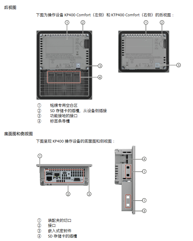
3. Installation and connection process
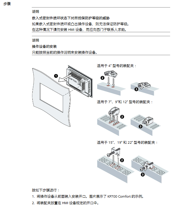
(1) Installation preparation
It is necessary to check the integrity of the packaging and confirm the environmental conditions (temperature, humidity, air pressure). The installation opening should match the equipment size (material thickness 2mm-6mm, surface roughness ≤ 120 μ m) to ensure the protection level (IP65 on the front and IP20 on the back).
Reserved heat dissipation gap: left and right ≥ 15mm, up and down ≥ 50mm, back ≥ 10mm, supports horizontal/vertical installation (some models), maximum tilt angle ± 35 °.
(2) Installation steps
Insert the device into the installation opening from the front and secure it with the matching assembly clip (torque: 4 "model 0.2Nm, 7" -22 "model 0.5Nm), ensuring that the embedded seal fits snugly without distortion.
The function keys need to be marked with a dedicated marker strip (thickness 0.15mm, direct writing is prohibited), and the template can be obtained through the official website or WinCC installation directory.
(3) Connection specifications
Connection sequence: equipotential bonding → power supply → controller → configuration PC → peripheral devices (USB devices, printers, etc.)
Communication connection:
Supports PROFINET (10/100/1000Mbps), PROFIBUS DP (maximum 12Mbps), RS422/485 interfaces
Can communicate with SIMATIC S7-200/300/400/1200/1500, third-party controllers (such as Allen Bradley, Modicon)
USB interface (Type A for peripheral devices, Mini Type B for debugging), audio output interface (some models)
Equipotential bonding: Copper or galvanized steel wires with a cross-sectional area of ≥ 16mm ² should be used, and the cross-sectional area of the wire between the grounding bar and the equipment should be ≥ 4mm ².
4. Equipment debugging and system configuration
(1) Basic debugging
Memory management: Supports memory, SD/MMC memory cards, USB storage media, and system memory cards (≥ 2GB) can achieve automatic backup and fast fault recovery.
Control panel functions: configurable network parameters (IP address, PROFINET device name), display settings (brightness, orientation), touch screen calibration, password protection, screen saver, sound signals, etc.
Safe mode: Protect the control panel and taskbar with a password to prevent unauthorized modifications.
(2) Network and Communication Configuration
Support DHCP automatic allocation or static IP settings, PROFINET device names must be unique and comply with the DNS protocol.
Configurable MPI/PROFIBUS DP parameters (bus address, transmission rate), NTP time synchronization, proxy server, email configuration, Telnet remote control, etc.
(3) Service and maintenance functions
Backup and Recovery: Supports backing up projects, recipes, user data, etc. through WinCC or ProSave, with a backup file format of *. psb.
Operating system update: It can be updated through external storage media or configuration PC. Before updating, the automatic backup function must be disabled to avoid data loss.
Automatic backup: can be activated after inserting the system storage card, real-time synchronization of device data, and quick recovery in case of failure.
5. Project implementation and operation
(1) Project transmission and testing
Transmission method: Supports manual/automatic transmission from the configuration PC, or loading projects through external storage media. Automatic transmission is suitable for the testing phase and is recommended to be disabled after debugging is completed.
Operation mode: divided into three modes: offline (communication without controller), online (communication with controller), and transmission (project transmission/data backup), which can be switched through project configuration operation elements.
Test types: offline testing (verifying interface and operation), online testing (verifying communication and functionality), which requires checking screen layout, navigation, input objects, measurement value updates, etc.
(2) Project Operations
Operation mode: Touch screen (sharp objects are prohibited from touching), device keyboard, external USB keyboard/mouse, supporting single touch, function key operation, and numerical input (numbers/alphanumeric).
Core operations: language switching (up to 32 languages), function key operations (global/screen specific functions), direct keys (quick control of PLC I/O bits), information text viewing, project closure, etc.
Numerical input: The on-screen keyboard automatically pops up, supporting range verification and decimal filling. Exceeding the limit will trigger an alarm and reject input.
6. Maintenance and troubleshooting
(1) Daily maintenance
Cleaning: After turning off the power or locking the touch screen, wipe it with a cloth dipped in neutral cleaner. Do not use compressed air or corrosive solvents.
Repair: Only Siemens approved spare parts are allowed. In case of malfunction, contact official technical support and provide information such as equipment model and image version.
Recycling: It must be processed by certified electronic waste recycling companies and comply with local environmental regulations.
(2) Common fault handling
System memory card error: Check if the memory card is compatible (≥ 2GB SIMATIC HMI memory card), replace the faulty memory card.
Communication failure: Verify IP address/bus address uniqueness, cable connection and shielding, controller model compatibility.
Touch screen unresponsive: recalibrate the touch screen and check for physical damage.
7. Core parameters of technical specifications
Display specifications: 16 million color TFT widescreen, resolution of 480 × 272 to 1920 × 1080, backlight life of 30000-8000 hours (varies by model).
Communication performance: PROFINET has a maximum transmission rate of 1000Mbps, PROFIBUS DP has a maximum speed of 12Mbps, and supports secure HMI communication (TIA Portal V17 and above).
Software features: WinCC supports up to 750 images, 6000 discrete alarms, 500 recipes, and supports VBScript extension, data archiving (CSV/RDB/TXT format), and user permission management (up to 50 user groups).
Protection level: IP65 on the front and IP20 on the back, in compliance with IEC 60529 standard.
Key precautions
Strictly follow the requirements for heat dissipation and protection during installation, otherwise it will affect the lifespan of the equipment and the effectiveness of certification.
When used in explosive hazardous areas, it is prohibited to plug and unplug connectors and storage cards with power on, and it is necessary to ensure that the plugs are not loose.
Before transferring the project, it is necessary to confirm that the device firmware is compatible with the WinCC version. Updating the operating system will clear all data, so it is important to backup in advance.
Network configuration should avoid IP address conflicts, and PROFINET device names and computer names should be configured separately.
Touch screen calibration requires the use of a stylus or fingers to avoid damage caused by sharp objects.
- YOKOGAWA
- Reliance
- ADVANCED
- SEW
- ProSoft
- WATLOW
- Kongsberg
- FANUC
- VSD
- DCS
- PLC
- man-machine
- Covid-19
- Energy and Gender
- Energy Access
- Renewable Integration
- Energy Subsidies
- Energy and Water
- Net zero emission
- Energy Security
- Critical Minerals
- A-B
- petroleum
- Mine scale
- Sewage treatment
- cement
- architecture
- Industrial information
- New energy
- Automobile market
- electricity
- Construction site
- HIMA
- ABB
- Rockwell
- Schneider Modicon
- Siemens
- xYCOM
- Yaskawa
- Woodward
- BOSCH Rexroth
- MOOG
- General Electric
- American NI
- Rolls-Royce
- CTI
- Honeywell
- EMERSON
- MAN
- GE
- TRICONEX
- Control Wave
- ALSTOM
- AMAT
- STUDER
- KONGSBERG
- MOTOROLA
- DANAHER MOTION
- Bentley
- Galil
- EATON
- MOLEX
- Triconex
- DEIF
- B&W
- ZYGO
- Aerotech
- DANFOSS
- KOLLMORGEN
- Beijer
- Endress+Hauser
- schneider
- Foxboro
- KB
- REXROTH
- YAMAHA
- Johnson
- Westinghouse
- WAGO
- TOSHIBA
- TEKTRONIX
- BENDER
- BMCM
- SMC
- HITACHI
- HIRSCHMANN
- XP POWER
- Baldor
- Meggitt
- SHINKAWA
- Other Brands
- UniOP
- KUKA
- IBA
- Beckhoff
-
LTI SC52.0040.0012.0000.0 - Servo Drive
-
Lti SC52.0040.0012.0000.0 - Servo Drive
-
Milton Industries LTI Tool By Milton LT1240 - 1/2" Drive Lugnut Remover
-
LTi Drives SO84.200.P030.0000.0-W - Servo Spindle Drive
-
LTI DRIVES LSP08-035-320-30-B0R1PY170 - Servo Motor
-
LTI DRIVES SE84.200.SC00.0001.0-W - Servo Drive
-
Lust CDE34.005.W2.2 - Lti Drives Controller
-
LTi SO84.012.0030.0011.2 - ServoOne Servo Drive
-
LTi Drives SO CM-P.0010.11.00.0 - Servo Drive Controller
-
LTi CDE34.017.W3.0 - Servo Drive
-
LTI Drives CDB32.004, C2.0,SH - Positioning Controller
-
LUST CM-CAN1 - LTi DRIVES Communication Module
-
LTi SO84.012.1030.0000.2 - Servo Drive
-
LTI MOOG CDE54.044 - PITCHMASTER FREQUENCY CONVERTER 181-01019
-
MOOG LTI 181-01019 CDE54.044 - PITCHMASTER FREQUENCY CONVERTER
-
Lust LTi Drives CDE34.010,D2.0 - Servo Drive Controller
-
LTI SO84.032.0003.0101.2 - Servo Drive
-
Seagate 9CC132-302 Harris LTI-CS IRT-34-0021-01 - Hard Drive 160GB
-
LTI SO84.032.0003.0001.2 - Servo Drive
-
LTI SO24.007.0070.0000.1 - SERVO CONTROLLER
-
LTi drive CDA32.003.C3.0.H05-01.PC1 - Servo Drive
-
LTI SO84.016.0030.0000.2 - SERVO CONTROLLER
-
LUST LTI CD A34.008,W1.4, BR - SERVO DRIVE
-
MOOG LTI 181-01019 CDE54.044 - PITCHMASTER FREQUENCY CONVERTER
-
LTI MOOG 181-01019 - PITCH Master Servo Drive CDE54.044
-
LTI SERVO ONE SO84.045.0030.0001.2-W - Drive
-
LUST LTi SO84.032.0040.0000.2 - SERVO ONE DRIVE
-
LTi Drives LSH-074-2-30-3 20/T1,G6.1M - SERVO MOTOR
-
LTI SO84.016.0000.0101.2 - servo drive
-
LTI SA54.0550.0033.0000.0 - Servo Drive
-
LTI SA54.0550.0033.0000.0 - Servo Drive
-
LTI LT 4850 - 3/8" Drive 3-Pc Twist Socket Transmission Drain Plug Removal System
-
LTI Tools LT4400-30 Lock Technology - 3/4" Twist Socket 1/2" Drive Lugnut Remover
-
LTI Tools LT-1400C - 1/2 Drive Wheel Torque Extension Tool
-
LTI Tools LT1250 - 1/2" Drive Dual Sided Socket Lug Nut Remover Tool
-
LTI SO84.032.0003.0101.2 - Servo Drive
-
LTI MOOG 181-01019 - PITCH Master Servo Drive CDE54.044
-
MOOG LTI 181-01019 CDE54.044 - PITCHMASTER FREQUENCY CONVERTER
-
MOOG LTI 181-01019 CDE54.044 - PITCHMASTER FREQUENCY CONVERTER
-
MOOG LTI 181-01019 CDE54.044 - PITCHMASTER FREQUENCY CONVERTER
-
LTI SA54.0550.0033.0000.0 - Servo Drive
-
LTI Tools LT-4800 - 7 Piece Twist Socket 3/8" Drive Oil Drain Plug Removal Set
-
LTI SA54.0550.0033.0000.0 - Servo Drive
-
LTI Drive SO24.007.00300000.0 - Servo Drive
-
LTI TOOLS LTI 1400-I - Drive Wheel Torque Extension
-
LTI Tools LT4400-3 - 3/4" 19mm Twist Socket 1/2" Drive Lugnut
-
LTI TOOLS LTI 1400-BB - Drive Wheel Torque Extension
-
LTI SO84.032.0003.0101.2 - Servo Drive
-
LTI Tools LT-4512 - 3/8" Drive 12mm Twist Socket
-
LTI MOTION Luster SO84.032.0003.0001.2 - Servo Drive
-
LTI Tool By Milton LT1600P - 1" Drive Torx Stick
-
LTI Lust VF1424L,HF,OP2,S56 - Variable Frequency Drive
-
LUST CDA32.004,C1.4,H08,B0 - SERVO DFRIVE CM-CAN1 Module
-
LTI SO84.045.0002.0001.2-W - Drive
-
LTI Lust VF1404M,C9,PT1,BR1 - Inverter Type VF1404M
-
LTI SA54.0550.0033.0000.0 - Servo Drive
-
LTI Tools LT-1400C - 1/2" Drive Wheel Torque Extension
-
Lust LTI DRiVES CDA32.006, C3.0, H09 - Variateur De Fr茅quence Frequency Inverter
-
LTI MOOG CDE54.044 - PITCH master SERVO DRIVE
-
LTI MOOG CDE54.044 - PITCH master SERVO DRIVE
-
LTI SO84.143.0020.0101.2-W - servo drive
-
LTI MOTION SC34.0200.0011.0000.0 - Servo drives
-
LTI SO84.032.0003.0001.2 - Servo Drive
-
LTI DRIVES GmbH MS100 - Assembly Set Mounting Kit
-
LTI SO84.032.0003.0001.2 - Servo Drive
-
LTI SO84.032.0003.0001.2 - Servo Drive
-
LTI MOTION SO84.032.0003.0101.2 - servo drive
-
LTI SO84.032.0003.0101.2 - Servo Drive
-
LTI MOOG CDE54.044 - PITCH master SERVO DRIVE
-
LTI MOTION CDE32.004.C2.4 - Servo drives
-
LTI CDD34.032锛學x.x锛孊R锛孭C1 - Servo Drive
-
Lust LTI DRiVES CDA32.006, C3.0, H09 - Inversor De Frecuencia Frequency Inverter
-
Lust SO84.008.0030.1000.0 - Servo One LTi Drive
-
LTI MOTION SO84.032.0003.0101.2 - Servo drives
-
LUST LTi CDA32.004,C1.4 - SERVO DRIVE
-
LTI MOOG CDE54.044 - PITCH Master SERVO DRIVE
-
LTI KEBA CDB32.004 C2.7, SH - PN: 08673530 Frequency Inverter
-
LTI Tools LT-1400C - 1/2" Drive Wheel Torque Extension
-
LTI LT1400-E - 1/2" Drive Wheel Torque Extension
-
LTI MOOG 181-01019 - PITCH master SERVO DRIVE CDE54.044
-
LTI LSN-097-0510-30-560/T1 - Actuator Motor
-
LTI Tools LT 4800 - 7 Piece 3/8" Drive Twist Socket Oil Drain Plug Removal System
-
LTI DRIVES GmbH MS100 - MONTAGESET Assembly Set Mounting Kit
-
Lti SC52.0040.0012.0000.0 - Servo Drive
-
LTI DRIVES GmbH MS100 - Juego De Montaje Assembly Set Mounting Kit
-
LTi DSM4-14.2-21R83-200 - Drives servomoteur Servo Motor
-
MOOG CDE 54.044.GDA - Pitch Master Industrielle Turbine Lti Drive
-
LTI SO24.004.0030.1000.0 - Servo Drive Controller
-
Lti MOOG CDE54.044 - Pitch Master Servo Drive
-
Lust LTI DRiVES CDA32.006, C3.0, H09 - Inverter
-
LTI MOTION GMBH CDB34.006,W3.0,PC1,H39 - Frequency inverter
-
LTI SO84.032.0003.0001.2 - Servo Drive
-
MOOG CDE 54.044.D - Pitch Master Industrielle Turbine Lti Drive
-
LTI TOOLS LT-1460 - 1/2" DRIVE WHEEL TORQUE EXTENSION KIT 5 PIECE SET
-
Lust Cdb32.003, C2.4 - Lti Drives Servoregulador Frecuencia Servo Controller Inverter
-
Lust LTI DRIVES CDA32.006, C3.0, H09 - Frequency Inverter
-
Lust Lti SO82.004.0030.0000.2 - Servo Drive
-
LTI MOTION SC34.0200.0011.0000.0-SL - Servo drives
-
LTI MOTION SA54.0075.0033.0000.0 - Servo drives
-
LTI MOTION SC32.0075.1011.0000.0 - Servo drives
-
LTI Servo-One Junior SO22.006.0080.1000.0 - Servo Controller Servoregler
-
LUST CDA32.004, C1.4, H08, B0 - Servo Drive & LTI CM-CAN1 Module
-
LTI DRIVES LSP08-035-320-30-B0R1PY170 - Servo Motor
-
LUST LTI CDA32.004,C1.4.H08.B0 - SERVO CONTROLLER DRIVES
-
LUST LTi DRiVES CDS44.072LC1.2 - Servo Drive
-
Lti Servo-One Junior SO22.006.0082.1000.0 - Servo Controller Servoregler
-
LUST CDA32.008,C2.0,HF - Lti DRIVES Spindle Drive Inverter
-
LTI SO22.003.0082.0000.0 - Servo Drives One junior Servo Controller Servoregler
-
Lust Lti Drives CM-CAN1 - Communication Module
-
LUST Lti Drives Vf1202s, G8, I6 - Frequency Inverter Drive
-
LTI DRIVES BR-090.03.540.UR.H38 - Bremswiderstand Brake Resistor
-
LTi DRIVES PM-E40.2DRA054P - Wind Turbine Pitch Control Inverter
-
LTi Drives GmbH br-110.01.540-UR - Brake Resistor
-
LTI Drives LSN-097-0960-30-0560/T1,S4,B - Servo Motor
-
LUST CDA34.006.C2.0 - LTI Drives Servoregler
-
LUST LTI DRIVES SERVO ONE JUNIOR SO24.002.0020.0000.1 - Servo Drive Controller
-
LTI MOTION SO84.032.0003.0001.2 - Servo drives
-
LTI DDTD750V2-120 - IBOP ACTUATOR CYLINDER FOR TOP DRIVE
-
LTI CDE32.004, C2.4 - SERVO DRIVE
-
LUST LTI DRIVES CDD34.017 W3.4PC1 - Servo Drive Controller
-
LTI CDA3208,C3,0,HF - AC SERVO DRIVE
-
LUST LTI DRIVES LSH-074-3-30-560/T1,G6.1S - SERVO MOTOR
-
LUST Lti CDB32.004.C2.4.SH - AC Servo Drive
-
LTi CDA32.006, C3.0, H09 - Servo Drive
-
LTI SO22.003.0010.0000.0 - Servo Drive Servo one junior Servoregler Controller
-
LTi Drives DSM4-14.2-21R83-200 - Servo Motor
-
LUST Lti Drives Lsh-097-1-30-560/T1, 1R - Servomotor
-
LTI 1237 - 7 Piece 1/2" Drive Flip Socket Set

K-JIANG

Add: Jimei North Road, Jimei District, Xiamen, Fujian, China
Tell:+86-15305925923