
K-WANG


MOOG M3000 ® Control system and MSC servo controller
MOOG M3000 ® Control system and MSC servo controller
MOOG M3000 ® It is a modular distributed intelligent control system, consisting of MSC (Moog Servo Controller) servo controller, Q series local expansion module, R series remote module and supporting software. It supports Ethernet, CANopen, TIA/EIA 232/422/485 multiple communication interfaces, equipped with 8 digital I/O (configurable), 8 analog inputs, 2 analog outputs and 2 digital sensor interfaces. It requires 24VDC SELV power supply and has a working temperature range of * *+5 ℃ to+55 ℃. It is programmed and configured through MACS development environment * * (compatible with IEC 61131 standard) and has safety functions such as watchdog and output enable. It can form multiple control groups through E-bus/LocalCAN/WideCAN, which is widely applicable. In high-end control scenarios such as electro-hydraulic drive and industrial automation.
Overall Overview of the System
Moog M3000 ® The control system is a modular solution for mid to high end industrial control scenarios. Its core advantages lie in distributed intelligent architecture, multi-dimensional scalability, and high safety. By combining different functional modules, it can quickly build complex systems ranging from single axis control to multi axis collaboration. It is suitable for various applications such as hydraulic drive, automated production lines, and precision motion control, and meets international standards such as CE and IEC 61131-2, with EMC electromagnetic compatibility.
Detailed explanation of core hardware components
(1) MSC servo controller (core module)
Detailed explanation of key parameters for categories
Core configuration processor 40MHz 32-bit PowerPC RISC with floating point unit (FPU)
Storage system flash/memory 4MB Flash EEPROM (storing boot items/RETAIN variables), 2/4MB RAM
Number/configuration of 8 digital I/O channels, each channel can be independently configured as input or output, supporting open collector electrode/development emitter output
Analog input specification: 8-channel differential input, configurable as ± 10V/± 10mA/4-20mA, 16 bit resolution, maximum error ± 0.5% FS
Analog output specifications include 2 channels, with a voltage output of ± 10V (load ≥ 1k Ω) and a configurable current output of ± 10mA/± 50mA/4-20mA
Sensor interface type: 2-channel TIA/EIA 422 interface, supporting SSI sensors (master/slave mode) and incremental sensors (up to 8MHz pulse frequency)
Communication interface type Ethernet(RJ45)、CANopen(LocalCAN/WideCAN)、TIA/EIA 232/422/485、E-bus
Power requirements: Input/power consumption 24VDC SELV (compatible with 18-36V), static current ≤ 0.5A, digital I/O independent power supply (L2+/M2)
Environmental characteristics Working conditions Temperature+5 ℃ to+55 ℃, humidity 10% -95% (non condensing), protection level IP20, altitude ≤ 2000m
(2) Expansion module classification
Module Series Type Core Function Connection Method
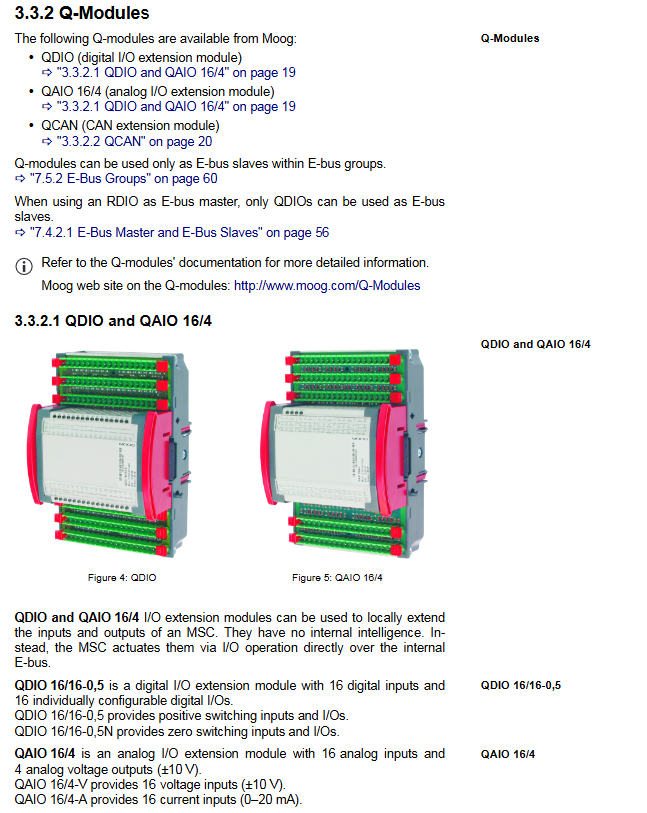
Q series (local expansion) QDIO 16 channel digital input+16 channel digital I/O, supporting positive/zero switching E-bus
QAIO 16/4 16 channel analog input+4 channel analog output (voltage type) E-bus
QCAN LocalCAN bus extended to external devices, D-sub interface E-bus
R series (remote module) RDIO 16 channel digital input+16 channel digital I/O, with CANopen interface CAN bus
RTEMP 8-channel temperature control, supporting TIA/EIA 232/CANopen CAN bus
RDISP 22 key display operation terminal with graphic LCD CAN bus
(3) Starter Kit configuration
Component specifications and usage
MSC controller 2MB RAM, developing control core for emitter output system
Power supply 24VDC 10A, DIN rail installation system power supply
QDIO module 16/16-0,5 type digital I/O expansion
Software MACS development environment+1-year maintenance contract programming configuration
Cable cross Ethernet (10m), TIA/EIA 232 (5m), CAN bus (3m) equipment interconnection
Terminal block 18 poles x 11, 9 poles x 1 signal wiring
System Software and Programming
MACS development environment
Compatibility standard: IEC 61131, supports 6 programming languages including IL (instruction list), ST (structured text), LD (ladder diagram), etc
Core functions: hardware configuration, program writing/compilation/download, online debugging (breakpoints/single steps), visual monitoring
Communication parameters: Ethernet default IP 10.49.40.1 (port 1200), TIA/EIA 232 baud rate 38400bps
supporting software
MACS HMI: Independent visualization package, can run without development environment, supports 1-50 system authorizations
CPRTEMP: RTEMP temperature module dedicated configuration software
CPRDISP: RDISP Display Terminal Specific Configuration Software
Authorization mechanism
Required components: License key (divided into Controls gray/Motion green, storing CANopen node ID/IP address)
Functional difference: Green authorization supports PLCopen motion control library, while gray authorization only includes basic control library
System networking and expansion
(1) Control group type
Control group type, connection method, maximum number of nodes, core usage
E-bus group module lateral Q-connector MSC up to 7 slave stations, RDIO up to 6 slave stations local I/O expansion, short distance high-speed communication
The LocalCAN group module has a built-in Q-connector for 64 network stations to collaborate with local devices, supporting QCAN extension to external devices
WideCAN front-end WCAN interface with 64 network stations for cross regional control group synchronization, connected to remote R module
(2) Security function
Watchdog monitoring: Implement software and hardware fault detection through the M-WATCHDOG function block, disable all outputs after timeout
Output Enable (OutEN): It must meet the three conditions of "valid authorization+fault free program+normal watchdog" before it can be activated, and the LED indicates the status in real time
Low voltage detection: When the voltage is below 16V (typical value), the SAVE state is triggered, and the output is disabled after saving key data
Wiring protection: Digital I/O supports reverse polarity protection, and analog channels have ± 36V overvoltage protection
Installation and maintenance
Installation requirements
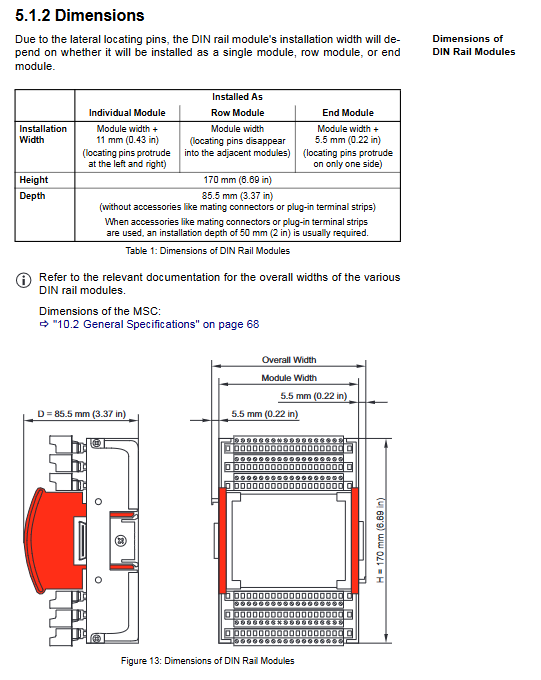
Mechanical installation: 35mm DIN top cap guide rail (TH 35-7.5), vertically mounted board grounded, module spacing ≥ 30mm
Grounding specification: centralized single point grounding, DIN rail and protective earth (PE) low resistance connection
Cable requirements: Shielded twisted pair (copper core ≥ 0.25mm ²) for analog signals, CAN bus impedance 120 Ω
Maintenance points
Module features: maintenance free design, no built-in battery, Flash data retention>10 years
Fault diagnosis: Front end LED indicates power, communication, I/O status, and line faults, supporting MACS online diagnosis
Repair service: Only Moog authorized service providers provide Authentic Repair, with a dedicated seal affixed after repair
Product Resources and Accessories
Category Core Product Specifications/Usage
Interface cable cross Ethernet cable 10m, RJ45 connector, used for connecting MSC and PC
CAN bus cable 3/10m, 9-pin D-sub, impedance 120 Ω
Terminal block plug-in terminal block with 8/9/18 poles, supporting screw/spring wiring (wire diameter ≤ 2.5mm ²)
CAN accessory terminal resistor 120 Ω, 9-pin D-sub, used for matching the two ends of the bus
USB-CAN adapter USB1.1 to CAN, supports computer debugging
Training service software training in both English and German, including IEC 61131 programming and MACS operation
Hardware training in both English and German, including module configuration, networking, and control library usage
- YOKOGAWA
- Reliance
- ADVANCED
- SEW
- ProSoft
- WATLOW
- Kongsberg
- FANUC
- VSD
- DCS
- PLC
- man-machine
- Covid-19
- Energy and Gender
- Energy Access
- Renewable Integration
- Energy Subsidies
- Energy and Water
- Net zero emission
- Energy Security
- Critical Minerals
- A-B
- petroleum
- Mine scale
- Sewage treatment
- cement
- architecture
- Industrial information
- New energy
- Automobile market
- electricity
- Construction site
- HIMA
- ABB
- Rockwell
- Schneider Modicon
- Siemens
- xYCOM
- Yaskawa
- Woodward
- BOSCH Rexroth
- MOOG
- General Electric
- American NI
- Rolls-Royce
- CTI
- Honeywell
- EMERSON
- MAN
- GE
- TRICONEX
- Control Wave
- ALSTOM
- AMAT
- STUDER
- KONGSBERG
- MOTOROLA
- DANAHER MOTION
- Bentley
- Galil
- EATON
- MOLEX
- Triconex
- DEIF
- B&W
- ZYGO
- Aerotech
- DANFOSS
- KOLLMORGEN
- Beijer
- Endress+Hauser
- schneider
- Foxboro
- KB
- REXROTH
- YAMAHA
- Johnson
- Westinghouse
- WAGO
- TOSHIBA
- TEKTRONIX
- BENDER
- BMCM
- SMC
- HITACHI
- HIRSCHMANN
- XP POWER
- Baldor
- Meggitt
- SHINKAWA
- Other Brands
- UniOP
- KUKA
- IBA
- Beckhoff
- ADLINK
-
ADLINK HPCI-14S12U - Industrial Control Backplane 12PCI Backplane PCI-14S Passive Backplane
-
ADLINK PCIe-GIE74C - image acquisition card 4-CH GigE Vision PoE+ Frame Grabber
-
ADLINK PCI-8164 - control card 4-Axis Advanced Motion Controller Board
-
ADLINK PCIe-U304 - 4 Port USB3 PCIe Frame Grabbers USB Screw Hole Card
-
ADLINK PCI-9112 - Multi-Function Data Acquisition Card DAQ Card
-
ADLINK PCI-7432 - 51-12013-0A50 4-CH Isolated Numérique I/O PCI Cartes Digital I/O Card
-
ADLINK PCA-6106P3-0C1 REV.C1 - backplane 6-Slot Passive Backplane Board
-
ADLINK PCI-7224 - 24-CH Opto-Isolated Digital I/O PCI Board
-
ADLINK CPCI-7433R(G) - Digital Input Board Rear I/O CompactPCI Card
-
ADLINK EBP-13E4 - 51-46703-0A30 Industrial PC Backplane Passive Backplane
-
ADLINK PCIE-HDV62 - Image acquisition card High Definition Video Frame Grabber
-
ADLINK EBP-13E4 - 51-46703-0A30 Industrial Backplane Board Passive Backplane
-
ADLINK 90111-B1 / CPCI-6770 - PCB CPU MODULE CompactPCI Single Board Computer
-
ADLINK PCI-7248 - DATA ACQUISITION PCI CARD 48-CH Parallel Digital I/O Board
-
ADLINK PCI-7230 - 51-12003-0a50 board PCI7230 32-CH Isolated Digital I/O Card
-
ADLINK PCI2A000CB - 51-20000-0B30 Multi-Function DAQ Card Baseboard
-
ADLINK PCI-8134-005 - 4-Axis Motion Controller Card
-
ADLINK PCI-7224 - 24-CH Opto-Isolated Digital I/O PCI Card
-
ADLINK PCI-7434 - 64-CH Isolated Digital Output Card
-
ADLINK PCI-8132 - motion control card 2-Axis Servo & Stepper Controller
-
ADLINK PCI-8134 - Motion Controller PCI Card 4-Axis Controller Board
-
ADLINK PCI-8164 - Motion Control Card 51-12406-0A40 4-Axis Controller
-
ADLINK 51-12001-0C20 - Circuit Board Data Acquisition Interface Module Hardware
-
ADLINK NuPR0-840 - industrial control motherboard Full-Size PICMG CPU Board
-
ADLINK PCI-7444 - 51-12023-0A10 card 128-CH Isolated Digital Output Board
-
ADLINK PCI-1612B - data acquisition card 4-Port RS-232/422/485 Serial Communication Card
-
ADLINK PCI-6208V 009 - 8/16-CH 16-Bit Analog Output Cards PCB-I-E-482=6BX3
-
ADLINK NUPRO-935A/LV - industrial control motherboard Full-Size PICMG SBC Board
-
ADLINK PCI-9114DG - Multi-Function DAQ Card Data Acquisition PCI Card
-
ADLINK ACL-7130 - Data acquisition card Isolated Digital I/O Board
-
ADLINK ABX-6300D-4E1-BP - board ABX6300D4E1BP Video Interface Expansion Card
-
ADLINK CPCI-6940 - CPCI-6940/D1539/M16-0(EA)-000E 6U CompactPCI Processor Board
-
ADLINK NuPRO-760 - industrial control motherboard Half-Size PICMG SBC CPU Board
-
ADLINK IMB-M42H (G)-0020 - industrial control motherboard LGA1155 Micro-ATX Mainboard
-
ADLINK RTV-24 / PCI-MP4S - 51-12519-1C30 4-Channel Real Time Video Capture Board
-
ADLINK PCI-8134 - 4-Axis Servo & Stepper Motion Controller Card
-
ADLINK MXC-6101D - V.PC000.002.ST.00 Box PC Configurable Embedded Computer
-
ADLINK PCI-8134A - 51-12421-0A10 Motion Control Card 4-Axis Controller Card
-
ADLINK DIN-100S / DIN-100SA1 - Technology SCSI-II TB 100-PIN Terminal Block Board
-
ADLINK DIN-812M001 / DIN812M001 - 51-14034-0A1 51140340A1 Terminal Module Breakout Interface
-
ADLINK PCI-8164 - Servo motion control 4-Axis Advanced Controller Card
-
ADLINK PCIe-GIE64 - Acquisition card GigE Vision PoE+ Frame Grabber
-
ADLINK M-302 - Industrial control motherboard ATX PC Board Mainboard
-
ADLINK PCI-8134 - Motion Controller PCI Card 4-Axis Controller Board
-
ADLINK PCI-RTV24 - Image capture card Analog Video Frame Grabber
-
ADLINK PCI-8102 - Motion control card 2-Axis Servo & Stepper Controller Board
-
ADLINK PCI-9112 REV.B1 - Card Multi-Function Data Acquisition Card
-
ADLINK HSI-DI32-M-N / HSL-TB32-M-DIN - Discrete I/O MODULE Distributed Automation Module System
-
ADLINK PCI-7296 - IO card REV.A3 96-CH Parallel Digital I/O Card
-
ADLINK DIN-814P-A4 / 814Y - terminal board Motion Control Interface Block
-
ADLINK DIN-814P-A4 - 51-14056-0A10 PCB-I-E-2736=ZA01 Screw Terminal Board Breakout
-
ADLINK M-322 - motherboard Industrial Control Computer Mainboard
-
ADLINK NUPRO-406 REV:B1 - industrial control motherboard Full-Size PICMG CPU Board
-
ADLINK AMP-204C - card DSP-Based 4-Axis Advanced Pulse-Train Controller
-
ADLINK HPCI14S REV.B1 - industrial computer baseboard 14-Slot Passive Backplane
-
ADLINK PCI-7250 - 8-CH Relay Output & 8-CH Isolated DI PCI Card
-
ADLINK EBP-13E2 - baseplate Passive Backplane Industrial Computer Chassis Board
-
ADLINK LPCI-3488A - PCI-GPIB card 51-12801-0A30 acquisition card IEEE-488 Interface Board
-
ADLINK PCI-6216V-GL - 51-12201-0C30 16-CH 16-Bit Voltage Analog Output Card
-
ADLINK ACL-8454 - 16-CH Isolated Digital I/O & 4-CH Counter Card
-
ADLINK HPCI-9S7U - backplane Passive Backplane Compatible with NuPRO-A301 852 841 842
-
ADLINK DAQ-2010-007 - Simultaneous-Sampling Multi-Function Data Acquisition Card
-
ADLINK MP-C154 - 51-64205-0A10 Motion Control Card 4-Axis Controller Board
-
ADLINK MXE-202/mSSD16B/WiFi-BT - Matrix Rugged I/O Platform Embedded Fanless Computer
-
ADLINK CM-920-R-17 - PC/104-Plus Single Board Computer Module Intel Celeron M
-
ADLINK PCI-7250 NSMP - 8-CH Relay Output & 8-CH Isolated DI Card
-
ADLINK PCI-8164 - 4-Axis Motion Controller PCI Card W/ Cable and Breakout Box
-
ADLINK EMX-100 - Ethernet-based 4-axis Motion Controllers Distributed Motion Module
-
ADLINK PCI-8134A - Press control card 4-Axis Motion Controller Board
-
ADLINK M-845EG REV:3.2 - industrial motherboard Pentium 4 Socket 478 Micro-ATX
-
ADLINK PCI-9114A Rev A2 DG - card High-Resolution Multi-Function Data Acquisition Board
-
ADLINK IEC-915GV - REV 1.1 Industrial motherboard Socket 478 CPU Board
-
ADLINK PCI-9111DG(G) - Data Acquisition Card Multi-Function DAQ Card
-
ADLINK HPCI-15S10 REV:B2 - Industrial computer base plate Passive Backplane Board
-
ADLINK NuPR0-840 / NuPR0-840DV - industrial control motherboard Full-size PICMG CPU Board
-
ADLINK RTV-24 / PCI-MP4S - 51-12519-1C30 4-Channel Real Time Video Capture Board
-
ADLINK NUPRO-780 - industrial control motherboard Pentium III Single Board Computer
-
ADLINK PCI-7296 - 0050 card 96-CH Opto-Isolated Parallel DIO Card Set
-
ADLINK NUPRO-780 - industrial control motherboard PICMG Full-Size SBC
-
ADLINK PCI-7248 - 51-12006-0A3 002 Pci 7248 48-CH Parallel Digital I/O Card
-
ADLINK PCI-7230 - 32-CH Isolated Digital I/O Card
-
ADLINK AMP-204C - motion control card 4-Axis Advanced Controller Board
-
ADLINK PCI-1714UL - Card Ultra High-Speed 4-CH Simultaneous Sampling DAQ
-
ADLINK NuPRO-E330 - industrial computer equipment motherboard PICMG 1.3 SHB SBC
-
ADLINK AMP-204C - DSP-Based 4-Axis Advanced Pulse-Train Motion Controller Module
-
ADLINK PCI-7256 - 001 51-12206-0A2 REV.A2 LPCI-7256 16-CH Latching Relay Output Card
-
ADLINK ND6050 - NUDAM DIGITAL I/0 MODULE Distributed I/O Unit
-
ASEM BM100 - Box PC Embedded Fanless Industrial Computer
-
ADLINK PCI-7250 - PCI Acquisition Card 8-CH Relay Output & Isolated DI Board
-
ADLINK PCI-8164 - Servo motion control 4-Axis Controller Card
-
ADLINK NuPRO-A40H - Industrial Motherboard 51-41807-1A30 OSP LGA1155 H61
-
ADLINK ADMAX X300 SERVER - 51066010-0A30 motherboard Multi-Processor Mainboard
-
ADLINK CMe-GIE62+ - 51-32903-0A30 control card PC/104-Plus GigE Vision Frame Grabber
-
ADLINK NUPRO-780 - industrial control motherboard Full-Size PICMG SBC CPU Board
-
ADLINK ETX-AT-N270-18/GKTEL - 51-71111-OB10 motherboard ETX CPU Module Board
-
ADLINK DIN-812M - interface module Terminal Block Connection Board
-
ADLINK IMB-M42H - industrial control motherboard LGA1155 Micro-ATX Mainboard
-
ADLINK PXIS-2508 - 8-slot 3U PXI Instrument Chassis Power Hardware Assembly
-
ADLINK AMP-208C - Motion Control card DSP-Based 8-Axis Pulse-Train Controller
-
ADLINK PCI-9111 / PCI-9111DG - Multi-Function Data Acquisition Card DAQ Board
-
ADLINK IEEE-488 GPIB card - Bus Interface Controller Communication Board
-
ADLINK RTV-24 - 51-12519-1C30 image acquisition card Video Frame Grabber Card
-
ADLINK TB-24P/24-01 - Board 24 Way Screw Terminal Breakout Board
-
ADLINK HSL-DI16DO16-DB-NN - 51-23015-0A40 Distributed Discrete I/O Module Set
-
ADLINK PCI-7442 - switch quantity card data acquisition card 64-CH Isolated Card
-
ADLINK ACL-7130 REV. B2 - industrial control capture card Isolated Digital I/O PCI Card
-
ADLINK PCI-6S / PCI6S - Backplane 6-Slot Passive Backplane Chassis Board
-
ADLINK ACL-8113A - card Isolated Digital Input Card
-
ADLINK CPCI-6208V-003 - board cPCI CompactPCI 8-CH Analog Output Card
-
ADLINK DIN-100S-01(G) - SCSI 100-Pin Terminal Block Interface Board
-
ADLINK PCI-7433 - Isolated Digital Input Card 64-CH
-
ADLINK PCI-9812 - Synchronous sampling analog input card High-Speed DAQ Board
-
ADLINK PCI-7434 REV.B1 - PLOTECH PCB-I-E-1182=6EX2 64-CH Isolated Digital Output Card
-
ADLINK PCIe-RTV24 - 51-18016-0A20 4-CH Real-Time Video Capture Card PCIe Frame Grabber
-
ADLINK PCI-8144 / PCI-8144N - Motion control card 4-Axis Stepper Motor Controller
-
ADLINK DIN-68S-01 - terminal board 68-Pin Connector Terminal Block
-
ADLINK MP-C154 - Motion control card 4-Axis Advanced Controller Card
-
ADLINK PCI-7248 (G) - Motherboard 48-CH Parallel Digital I/O Card
-
ADLINK MXE-1301(G) - Intel Atom D2550+NM10 MXE 1300 Series 93-4130-0030 Embedded Computer
-
ADLINK PRO-841 Rev 2.0 / PRO-060907000670 - CPU 2.26GHz & RAM Industrial PC Board
-
ADLINK cPCI-6626 - 6U CompactPCI 2.0 Blades i7-2710QE PCB-I-E-2570=9N41
-
ADLINK MXC-6322D(G) - Industrial Fanless Computer
-
ADLINK cPCI-8168-004 - CompactPci NulPC Motion Control Board 51-36402-0A3
-
ADLINK CPCI-7300[G] - COMPACTPCI Digital I/O Card Data Acquisition
-
ADLINK CPCI-6626/2710/M4G - COMPACTPCI COMPUTER BOARD
-
ADLINK cPCI-8168-009 - cPCI NulPC Motion Control Board
-
ADLINK cPCI-6626/2710/M4G - VME CPU Board Computer Board
-
ADLINK CPCI-R6200(G)-0040 - COMPACTPCI CONTROL BOARD

K-JIANG

Add: Jimei North Road, Jimei District, Xiamen, Fujian, China
Tell:+86-15305925923