
K-WANG


MOOG M3000 ® Control System QAIO 16/4 Analog I/O Extension Module
MOOG M3000 ® Control System QAIO 16/4 Analog I/O Extension Module
The M3000 jointly launched by Moog and Berghof Automation Technology ® The user manual for the QAIO 16/4 series analog I/O expansion module (QAIO 16/4-V voltage type, QAIO 16/4-A current type) of the control system is a modular automation system based on CANbus, suitable for medium to high performance industrial control scenarios. The core consists of 16 analog inputs and 4 ± 10V analog voltage outputs, paired with a * *+10V reference voltage source * *. The input resolution is 11 bit+symbol, the working temperature is 5 ° C to 50 ° C, and the protection level is IP20. Shielding measures need to be taken to ensure accuracy. The manual specifies in detail the technical parameters, wiring installation, operation and maintenance, sensor/actuator connection, and safety specifications of the module. At the same time, it is clarified that the module does not have CE labeling, and users need to ensure the electromagnetic compatibility compliance of the system by themselves. The sentence is:.
Core features and technical parameters of the product
(1) Core functions and classification features
The module is used to expand the analog I/O capability of Cell Controllers, directly coupled through E-bus, and is divided into two models. The general characteristics and model specific characteristics are as follows:
General features: 4-channel ± 10V voltage output (GND detection), 1-channel+10V reference voltage output, small size/low installation depth, output resolution of 11 bits+symbol;
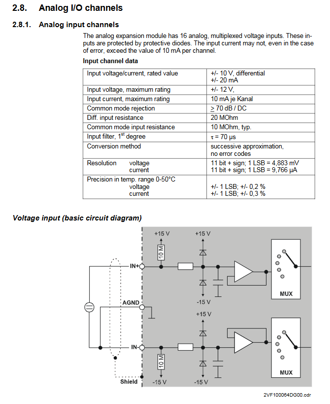
QAIO 16/4-V (voltage type): 16 differential ± 10V voltage inputs, compatible with active/passive resistors, resolution of 11 bits+symbol;
QAIO 16/4-A (current type): 16 channels of 0-20mA current input, resolution of 11 bits+symbol.
Supply list: only includes analog I/O expansion modules of corresponding models (voltage/current type).
(2) Key technical parameters
The core technical parameters of the module are all industrial grade standards. The physical, environmental, and power supply parameters are shown in the table below. The key parameters for analog input/output and reference voltage are detailed in the subsequent subdivision table
table
Category Technical Parameters
Size 124 × 170 × 85.5mm (modular size B=113/118.5mm)
Weight approximately 550g
Installation method NS 35/7,5 EN 50022 DIN rail
Working temperature 5 ° C to 50 ° C (no condensation)
Protection level IP20
Insulation test with 500VDC test voltage, in compliance with EN 61131-2
Supply voltage SELV DC+24V, maximum 0.3A, with reverse voltage protection
Maximum 300mA under no-load power consumption of DC+24V
Electrical isolation and E-bus optoelectronic isolation; Power supply and analog channels are not isolated
Four amber LED status indicators display L+, ± 15V,+5V, and OUT-ENA status respectively
EMC requires users to implement shielding measures, with emissions complying with EN 50081-2 and anti-interference complying with EN 50082-2
(3) Analog input/output/reference voltage core parameters
table
Category subdivision index Voltage type Input current type Input analog output Reference voltage source
Number of channels -16 16 4 1
Rated range - ± 10V (differential) 0~20mA ± 10V (floating)+10V
Resolution -11 bits+symbol 11 bits+symbol 11 bits+symbol-
LSB value -4.883mV 9.766 μ A 4.883mV-
Accuracy 25 ° C maximum error ± 0.1% full-scale ± 0.2% full-scale ± 0.15% full-scale 0.1%
Accuracy: Maximum error in the full temperature range ± 0.2% of full range ± 0.3% of full range ± 0.3% of full range-
Input impedance signal range 10M Ω 50 Ω --
Maximum output current -5mA 5mA
Protection Function Short Circuit Protection - Permanent Short Circuit Protection (Ikmax=25mA) Permanent Short Circuit Protection (Ikmax=25mA)
Common mode rejection DC/50/60Hz ≥ 70dB ≥ 70dB ± 2V Common mode range-
Overload capacity: Continuous maximum overload ± 30V 50mA --
Conversion speed channel transmission time<1ms<1ms<1ms<1ms-
Load requirement: capacitive load -<1000pF-
Load requirement: Resistive load - ≥ 2k Ω-
Module installation and wiring specifications
Installation requirements: The module must be installed inside a metal shielded cabinet/enclosure, and the cabinet must be isolated from interfering components and cables through measures such as wiring separation and component space isolation; The signal cable needs to be shielded at both ends, and the shielding layer of the cable at the entrance of the cabinet needs to be laid flat and grounded. Open wiring is strictly prohibited.
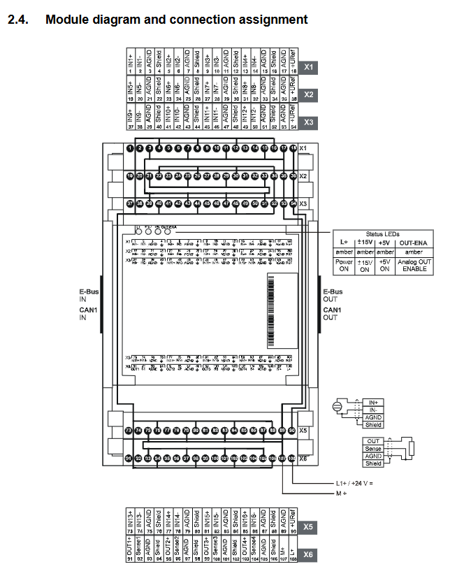
Wiring method: using vertical front wiring, equipped with a press type terminal block, supporting screw/crimping/clamping connections; The module is labeled with clear analog I/O channels, reference outputs, and terminal assignments for power supply, and must be wired according to the identification.
Shielding and anti-interference:
Low frequency interference (such as 50Hz power frequency) is offset by a differential measurement system and high common mode suppression;
High frequency/pulse interference needs to be isolated through shielding measures, and the cable shielding layer needs to be grounded at both ends on site (outside the cabinet);
The interaction between all analog components and auxiliary power supplies needs to be considered as a whole to ensure system immunity.
Module operation and usage
Initialization and recognition: Module recognition and initialization are automatically completed by the upstream Cell Controller operating system, without the need for dip switch settings; If the+24V power supply is interrupted or the E-bus transmission is interrupted, the analog output will reset to 0V and the OUT-ENA LED status will change.
Data measurement and conversion:
The transmission of measurement and data to CAN nodes is cyclic, controlled by the operating system API, and AD conversion does not require a startup signal;
Data conversion formula: U=10V × AD/2 ^ 15 (voltage), I=20mA × AD/2 ^ 15 (current), AD is the output value of the analog channel;
Over range output: positive over range is+32752 (+9.995V), negative over range is -32768 (-10.000V); When the sensor fails, the corresponding channel reports+9.995V to the controller.
Sensor/actuator connection: Differentiated wiring according to sensor type is required, with the following core requirements:
Floating ground sensor: Connect IN+/AGND through a 2-core shielded wire, and bridge at least one measurement input (IN -) to AGND to avoid capacitive signal coupling and false measurement;
Active sensor with auxiliary power supply: Connected to IN+/IN - through a 2-core shielded wire, sharing the same power supply with the module. The AGND module remains open to ensure potential balance;
Sensors using internal reference voltage: Connect IN+/IN -/Ref/AGND through a 3/4 core shielded wire. Potential sensors need to bridge idle inputs to AGND to avoid reference voltage overload.
Analog output usage: The output is a floating ground ± 10V voltage, and each output is equipped with AGND (analog ground) and REF (common ground) terminals, which can compensate for ground bias (must meet | UREF |<2V); The SENSE line is directly connected to the actuator ground and cannot be used alone as feedback.
Maintenance and after-sales standards
Daily maintenance: The module is maintenance free and the ventilation openings need to be kept unobstructed; Cleaning can only be done with dry, lint free cloth, and the use of cleaning agents is prohibited.
Repair requirements: Only the manufacturer or its authorized engineer can carry out repairs. Unauthorized repairs will void the warranty.
Scrap disposal: After the module reaches the end of its service life, it can be returned to the manufacturer for paid recycling, and the manufacturer will handle and recycle it uniformly.
Warranty policy: According to the statutory warranty conditions, if the module is repaired/modified without authorization, the warranty will immediately become invalid.
Nameplate information: The module nameplate includes barcode, identification number, module model, order number, version, power supply voltage, production date, etc. When ordering, only the model/order number needs to be provided. When replacing the module, the software version can be read through the CNW tool and the project version can be reloaded.
- YOKOGAWA
- Reliance
- ADVANCED
- SEW
- ProSoft
- WATLOW
- Kongsberg
- FANUC
- VSD
- DCS
- PLC
- man-machine
- Covid-19
- Energy and Gender
- Energy Access
- Renewable Integration
- Energy Subsidies
- Energy and Water
- Net zero emission
- Energy Security
- Critical Minerals
- A-B
- petroleum
- Mine scale
- Sewage treatment
- cement
- architecture
- Industrial information
- New energy
- Automobile market
- electricity
- Construction site
- HIMA
- ABB
- Rockwell
- Schneider Modicon
- Siemens
- xYCOM
- Yaskawa
- Woodward
- BOSCH Rexroth
- MOOG
- General Electric
- American NI
- Rolls-Royce
- CTI
- Honeywell
- EMERSON
- MAN
- GE
- TRICONEX
- Control Wave
- ALSTOM
- AMAT
- STUDER
- KONGSBERG
- MOTOROLA
- DANAHER MOTION
- Bentley
- Galil
- EATON
- MOLEX
- Triconex
- DEIF
- B&W
- ZYGO
- Aerotech
- DANFOSS
- KOLLMORGEN
- Beijer
- Endress+Hauser
- schneider
- Foxboro
- KB
- REXROTH
- YAMAHA
- Johnson
- Westinghouse
- WAGO
- TOSHIBA
- TEKTRONIX
- BENDER
- BMCM
- SMC
- HITACHI
- HIRSCHMANN
- XP POWER
- Baldor
- Meggitt
- SHINKAWA
- Other Brands
- UniOP
- KUKA
- IBA
- Beckhoff
- ADLINK
-
ADLINK HPCI-14S12U - Industrial Control Backplane 12PCI Backplane PCI-14S Passive Backplane
-
ADLINK PCIe-GIE74C - image acquisition card 4-CH GigE Vision PoE+ Frame Grabber
-
ADLINK PCI-8164 - control card 4-Axis Advanced Motion Controller Board
-
ADLINK PCIe-U304 - 4 Port USB3 PCIe Frame Grabbers USB Screw Hole Card
-
ADLINK PCI-9112 - Multi-Function Data Acquisition Card DAQ Card
-
ADLINK PCI-7432 - 51-12013-0A50 4-CH Isolated Numérique I/O PCI Cartes Digital I/O Card
-
ADLINK PCA-6106P3-0C1 REV.C1 - backplane 6-Slot Passive Backplane Board
-
ADLINK PCI-7224 - 24-CH Opto-Isolated Digital I/O PCI Board
-
ADLINK CPCI-7433R(G) - Digital Input Board Rear I/O CompactPCI Card
-
ADLINK EBP-13E4 - 51-46703-0A30 Industrial PC Backplane Passive Backplane
-
ADLINK PCIE-HDV62 - Image acquisition card High Definition Video Frame Grabber
-
ADLINK EBP-13E4 - 51-46703-0A30 Industrial Backplane Board Passive Backplane
-
ADLINK 90111-B1 / CPCI-6770 - PCB CPU MODULE CompactPCI Single Board Computer
-
ADLINK PCI-7248 - DATA ACQUISITION PCI CARD 48-CH Parallel Digital I/O Board
-
ADLINK PCI-7230 - 51-12003-0a50 board PCI7230 32-CH Isolated Digital I/O Card
-
ADLINK PCI2A000CB - 51-20000-0B30 Multi-Function DAQ Card Baseboard
-
ADLINK PCI-8134-005 - 4-Axis Motion Controller Card
-
ADLINK PCI-7224 - 24-CH Opto-Isolated Digital I/O PCI Card
-
ADLINK PCI-7434 - 64-CH Isolated Digital Output Card
-
ADLINK PCI-8132 - motion control card 2-Axis Servo & Stepper Controller
-
ADLINK PCI-8134 - Motion Controller PCI Card 4-Axis Controller Board
-
ADLINK PCI-8164 - Motion Control Card 51-12406-0A40 4-Axis Controller
-
ADLINK 51-12001-0C20 - Circuit Board Data Acquisition Interface Module Hardware
-
ADLINK NuPR0-840 - industrial control motherboard Full-Size PICMG CPU Board
-
ADLINK PCI-7444 - 51-12023-0A10 card 128-CH Isolated Digital Output Board
-
ADLINK PCI-1612B - data acquisition card 4-Port RS-232/422/485 Serial Communication Card
-
ADLINK PCI-6208V 009 - 8/16-CH 16-Bit Analog Output Cards PCB-I-E-482=6BX3
-
ADLINK NUPRO-935A/LV - industrial control motherboard Full-Size PICMG SBC Board
-
ADLINK PCI-9114DG - Multi-Function DAQ Card Data Acquisition PCI Card
-
ADLINK ACL-7130 - Data acquisition card Isolated Digital I/O Board
-
ADLINK ABX-6300D-4E1-BP - board ABX6300D4E1BP Video Interface Expansion Card
-
ADLINK CPCI-6940 - CPCI-6940/D1539/M16-0(EA)-000E 6U CompactPCI Processor Board
-
ADLINK NuPRO-760 - industrial control motherboard Half-Size PICMG SBC CPU Board
-
ADLINK IMB-M42H (G)-0020 - industrial control motherboard LGA1155 Micro-ATX Mainboard
-
ADLINK RTV-24 / PCI-MP4S - 51-12519-1C30 4-Channel Real Time Video Capture Board
-
ADLINK PCI-8134 - 4-Axis Servo & Stepper Motion Controller Card
-
ADLINK MXC-6101D - V.PC000.002.ST.00 Box PC Configurable Embedded Computer
-
ADLINK PCI-8134A - 51-12421-0A10 Motion Control Card 4-Axis Controller Card
-
ADLINK DIN-100S / DIN-100SA1 - Technology SCSI-II TB 100-PIN Terminal Block Board
-
ADLINK DIN-812M001 / DIN812M001 - 51-14034-0A1 51140340A1 Terminal Module Breakout Interface
-
ADLINK PCI-8164 - Servo motion control 4-Axis Advanced Controller Card
-
ADLINK PCIe-GIE64 - Acquisition card GigE Vision PoE+ Frame Grabber
-
ADLINK M-302 - Industrial control motherboard ATX PC Board Mainboard
-
ADLINK PCI-8134 - Motion Controller PCI Card 4-Axis Controller Board
-
ADLINK PCI-RTV24 - Image capture card Analog Video Frame Grabber
-
ADLINK PCI-8102 - Motion control card 2-Axis Servo & Stepper Controller Board
-
ADLINK PCI-9112 REV.B1 - Card Multi-Function Data Acquisition Card
-
ADLINK HSI-DI32-M-N / HSL-TB32-M-DIN - Discrete I/O MODULE Distributed Automation Module System
-
ADLINK PCI-7296 - IO card REV.A3 96-CH Parallel Digital I/O Card
-
ADLINK DIN-814P-A4 / 814Y - terminal board Motion Control Interface Block
-
ADLINK DIN-814P-A4 - 51-14056-0A10 PCB-I-E-2736=ZA01 Screw Terminal Board Breakout
-
ADLINK M-322 - motherboard Industrial Control Computer Mainboard
-
ADLINK NUPRO-406 REV:B1 - industrial control motherboard Full-Size PICMG CPU Board
-
ADLINK AMP-204C - card DSP-Based 4-Axis Advanced Pulse-Train Controller
-
ADLINK HPCI14S REV.B1 - industrial computer baseboard 14-Slot Passive Backplane
-
ADLINK PCI-7250 - 8-CH Relay Output & 8-CH Isolated DI PCI Card
-
ADLINK EBP-13E2 - baseplate Passive Backplane Industrial Computer Chassis Board
-
ADLINK LPCI-3488A - PCI-GPIB card 51-12801-0A30 acquisition card IEEE-488 Interface Board
-
ADLINK PCI-6216V-GL - 51-12201-0C30 16-CH 16-Bit Voltage Analog Output Card
-
ADLINK ACL-8454 - 16-CH Isolated Digital I/O & 4-CH Counter Card
-
ADLINK HPCI-9S7U - backplane Passive Backplane Compatible with NuPRO-A301 852 841 842
-
ADLINK DAQ-2010-007 - Simultaneous-Sampling Multi-Function Data Acquisition Card
-
ADLINK MP-C154 - 51-64205-0A10 Motion Control Card 4-Axis Controller Board
-
ADLINK MXE-202/mSSD16B/WiFi-BT - Matrix Rugged I/O Platform Embedded Fanless Computer
-
ADLINK CM-920-R-17 - PC/104-Plus Single Board Computer Module Intel Celeron M
-
ADLINK PCI-7250 NSMP - 8-CH Relay Output & 8-CH Isolated DI Card
-
ADLINK PCI-8164 - 4-Axis Motion Controller PCI Card W/ Cable and Breakout Box
-
ADLINK EMX-100 - Ethernet-based 4-axis Motion Controllers Distributed Motion Module
-
ADLINK PCI-8134A - Press control card 4-Axis Motion Controller Board
-
ADLINK M-845EG REV:3.2 - industrial motherboard Pentium 4 Socket 478 Micro-ATX
-
ADLINK PCI-9114A Rev A2 DG - card High-Resolution Multi-Function Data Acquisition Board
-
ADLINK IEC-915GV - REV 1.1 Industrial motherboard Socket 478 CPU Board
-
ADLINK PCI-9111DG(G) - Data Acquisition Card Multi-Function DAQ Card
-
ADLINK HPCI-15S10 REV:B2 - Industrial computer base plate Passive Backplane Board
-
ADLINK NuPR0-840 / NuPR0-840DV - industrial control motherboard Full-size PICMG CPU Board
-
ADLINK RTV-24 / PCI-MP4S - 51-12519-1C30 4-Channel Real Time Video Capture Board
-
ADLINK NUPRO-780 - industrial control motherboard Pentium III Single Board Computer
-
ADLINK PCI-7296 - 0050 card 96-CH Opto-Isolated Parallel DIO Card Set
-
ADLINK NUPRO-780 - industrial control motherboard PICMG Full-Size SBC
-
ADLINK PCI-7248 - 51-12006-0A3 002 Pci 7248 48-CH Parallel Digital I/O Card
-
ADLINK PCI-7230 - 32-CH Isolated Digital I/O Card
-
ADLINK AMP-204C - motion control card 4-Axis Advanced Controller Board
-
ADLINK PCI-1714UL - Card Ultra High-Speed 4-CH Simultaneous Sampling DAQ
-
ADLINK NuPRO-E330 - industrial computer equipment motherboard PICMG 1.3 SHB SBC
-
ADLINK AMP-204C - DSP-Based 4-Axis Advanced Pulse-Train Motion Controller Module
-
ADLINK PCI-7256 - 001 51-12206-0A2 REV.A2 LPCI-7256 16-CH Latching Relay Output Card
-
ADLINK ND6050 - NUDAM DIGITAL I/0 MODULE Distributed I/O Unit
-
ASEM BM100 - Box PC Embedded Fanless Industrial Computer
-
ADLINK PCI-7250 - PCI Acquisition Card 8-CH Relay Output & Isolated DI Board
-
ADLINK PCI-8164 - Servo motion control 4-Axis Controller Card
-
ADLINK NuPRO-A40H - Industrial Motherboard 51-41807-1A30 OSP LGA1155 H61
-
ADLINK ADMAX X300 SERVER - 51066010-0A30 motherboard Multi-Processor Mainboard
-
ADLINK CMe-GIE62+ - 51-32903-0A30 control card PC/104-Plus GigE Vision Frame Grabber
-
ADLINK NUPRO-780 - industrial control motherboard Full-Size PICMG SBC CPU Board
-
ADLINK ETX-AT-N270-18/GKTEL - 51-71111-OB10 motherboard ETX CPU Module Board
-
ADLINK DIN-812M - interface module Terminal Block Connection Board
-
ADLINK IMB-M42H - industrial control motherboard LGA1155 Micro-ATX Mainboard
-
ADLINK PXIS-2508 - 8-slot 3U PXI Instrument Chassis Power Hardware Assembly
-
ADLINK AMP-208C - Motion Control card DSP-Based 8-Axis Pulse-Train Controller
-
ADLINK PCI-9111 / PCI-9111DG - Multi-Function Data Acquisition Card DAQ Board
-
ADLINK IEEE-488 GPIB card - Bus Interface Controller Communication Board
-
ADLINK RTV-24 - 51-12519-1C30 image acquisition card Video Frame Grabber Card
-
ADLINK TB-24P/24-01 - Board 24 Way Screw Terminal Breakout Board
-
ADLINK HSL-DI16DO16-DB-NN - 51-23015-0A40 Distributed Discrete I/O Module Set
-
ADLINK PCI-7442 - switch quantity card data acquisition card 64-CH Isolated Card
-
ADLINK ACL-7130 REV. B2 - industrial control capture card Isolated Digital I/O PCI Card
-
ADLINK PCI-6S / PCI6S - Backplane 6-Slot Passive Backplane Chassis Board
-
ADLINK ACL-8113A - card Isolated Digital Input Card
-
ADLINK CPCI-6208V-003 - board cPCI CompactPCI 8-CH Analog Output Card
-
ADLINK DIN-100S-01(G) - SCSI 100-Pin Terminal Block Interface Board
-
ADLINK PCI-7433 - Isolated Digital Input Card 64-CH
-
ADLINK PCI-9812 - Synchronous sampling analog input card High-Speed DAQ Board
-
ADLINK PCI-7434 REV.B1 - PLOTECH PCB-I-E-1182=6EX2 64-CH Isolated Digital Output Card
-
ADLINK PCIe-RTV24 - 51-18016-0A20 4-CH Real-Time Video Capture Card PCIe Frame Grabber
-
ADLINK PCI-8144 / PCI-8144N - Motion control card 4-Axis Stepper Motor Controller
-
ADLINK DIN-68S-01 - terminal board 68-Pin Connector Terminal Block
-
ADLINK MP-C154 - Motion control card 4-Axis Advanced Controller Card
-
ADLINK PCI-7248 (G) - Motherboard 48-CH Parallel Digital I/O Card
-
ADLINK MXE-1301(G) - Intel Atom D2550+NM10 MXE 1300 Series 93-4130-0030 Embedded Computer
-
ADLINK PRO-841 Rev 2.0 / PRO-060907000670 - CPU 2.26GHz & RAM Industrial PC Board
-
ADLINK cPCI-6626 - 6U CompactPCI 2.0 Blades i7-2710QE PCB-I-E-2570=9N41
-
ADLINK MXC-6322D(G) - Industrial Fanless Computer
-
ADLINK cPCI-8168-004 - CompactPci NulPC Motion Control Board 51-36402-0A3
-
ADLINK CPCI-7300[G] - COMPACTPCI Digital I/O Card Data Acquisition
-
ADLINK CPCI-6626/2710/M4G - COMPACTPCI COMPUTER BOARD
-
ADLINK cPCI-8168-009 - cPCI NulPC Motion Control Board
-
ADLINK cPCI-6626/2710/M4G - VME CPU Board Computer Board
-
ADLINK CPCI-R6200(G)-0040 - COMPACTPCI CONTROL BOARD

K-JIANG

Add: Jimei North Road, Jimei District, Xiamen, Fujian, China
Tell:+86-15305925923