
K-WANG


SEW MOVIDRIVE ® Technology application frequency converter
SEW MOVIDRIVE ® Technology application frequency converter
MOVIDRIVE ® The complete process of technology application frequency converter debugging through PROFIBUS DP-V1 fieldbus revolves around CFP21A fieldbus card (supporting addresses 1-125) MOVISUITE ® Engineering design software and TIA Portal programming tools are developed, covering PROFIBUS network configuration, frequency converter address setting, process data configuration MOVIKIT ® The key operations such as software module application (Velocity Drive/Positioning Drive) and equipment replacement emphasize EMC compliant wiring, diagnostic alarm function, and safety debugging specifications, which are suitable for industrial automation integration scenarios with PLCs such as SIMATIC S7.
Basic information of the document
Project Details
Applicable equipment MOVIDRIVE ® Technology application frequency converter (MDX9 series)
Core bus PROFIBUS DP-V1 (supports periodic/non periodic communication)
Key hardware includes CFP21A fieldbus card, USM21A interface adapter, CBG21A handheld controller
Support software MOVISUITE ® (Engineering Design), TIA Portal (PLC Configuration) MOVIKIT ® software module
Compliance standards PROFIBUS PI specification, IEC 61158 (bus cables), EMC wiring requirements
PROFIBUS network basic configuration
(1) Hardware and wiring requirements
Bus cable: shielded twisted pair (IEC 61158 type A), with a large area of grounding at both ends of the shielding layer
Bus terminal: PROFIBUS segment head and tail devices enable terminal resistors (integrated into the plug)
Address setting: Set through the DIP switch of CFP21A (1-125), default address is 4, and it needs to be restarted to take effect after modification
Wiring specifications: laid in separate trenches with power cables, with a spacing of ≥ 20cm; metal cable racks for industrial environments
(2) Equipment Description Document (GSD)
File Name: SEW_6011.gsd (Non modifiable)
Download path: SEW official website → Online Support → Data and Files → Software → Search for "GSD Files"
Function: Provide all the parameters required for frequency converter engineering design and data exchange, which is a prerequisite for PLC configuration
Core debugging process
(1) Preliminary preparation
Hardware connection: Engineering design computer → USM21A → Inverter X32 interface (9-pin D-type)
Address setting: Use the DIP switch of CFP21A to set the PROFIBUS address (1-125)
Software preparation: Install MOVISUITE ®、 TIA Portal, Download the latest GSD file
(2) PLC side configuration (TIA Portal)
Key instructions for steps and operation content
1. Create a new project and install the GSD file to import SEW_6011.gsd, ensuring version matching
2. Add PLC and set PROFIBUS interface to select SIMATIC S7, configure IP address
3. Add frequency converter device path: Other on-site devices → PROFIBUS DP → SEW-EURODRIVE → MOVI-C MOVIDRIVE
4. Allocate PROFIBUS address consistent with CFP21A set address
Add 5 configuration process data words from slot 2 onwards (5 words/8 words, up to 16 words)
Download the project to PLC, save the project, and establish the communication link
(3) Inverter side configuration (MOVISUITE) ®)
Network scanning: Select USB network type, scan and apply frequency converter devices
Device configuration: Assign device name, download MOVIKIT ® Software modules (recommended) or manually configuring process data sources
Parameter settings: Configure the mapping between set values and actual values, save the project and download it to the frequency converter
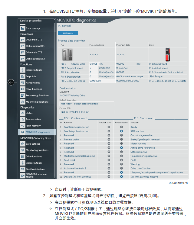
(4) Process data validation
Method 1: MOVIKIT ® Diagnostic Monitor
Monitoring mode: Observe the process data transmission between PLC and frequency converter (control word/status word/speed, etc.)
Control mode: Disable fieldbus data and set parameters directly through software (dangerous area needs to be locked)
Method 2: MOVISUITE ® Process data buffer
Check the consistency between PO data (PLC set value) and PI data (actual value of frequency converter)
Key functional modules
(1)MOVIKIT ® software module
Module Type Core Function Process Data Word Quantity Applicable Scenarios
Velocity Drive speed regulation drive, torque control 5-word ordinary speed regulation scenario
Positioning Drive 8-character high-precision positioning scene (machine tool/robot)
(2) Parameter access function module
Module Name: SEW-MOVI-CSingleParameterAccess (FB200)
Function: Read and write frequency converter parameters through non periodic communication via PROFIBUS
Supporting Protocol: Simple MOVILINK ® Protocol(SMLP)
Example project: TIA Portal example can be downloaded from the SEW official website
Fault diagnosis and equipment replacement
(1) LED indicator diagnosis
Measures for handling the meaning of LED name status
BF (red) long on communication interruption/unrecognized baud rate check cable/PLC configuration
BF (red 2Hz flashing) not addressed by PLC/configuration error check address/GSD file
RUN (green) constantly on, bus hardware is normal, no
RUN (red 2Hz flashing) Address 0 or>125 Reset address and restart
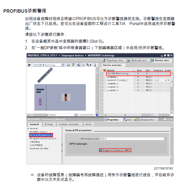
(2) Diagnostic Alert
Enabling method: TIA Portal device view → Slot 0 → General DP parameters → Enable diagnostic alerts
Function: Report fault number/description in text form to PLC component diagnosis
Default state: Factory enabled
(3) Equipment replacement
Operation: Insert the memory module of the old device into the new device (of the same model)
Inheriting data: driver parameters MOVIKIT ® Configuration, fieldbus settings, address information
Advantage: No need for reconfiguration, PLC automatically recognizes new equipment
Safety regulations
Network security: Restrict Ethernet/engineering interface access and comply with IT security standards
Debugging safety: Lock the hazardous area in control mode and activate existing safety devices
Wiring safety: Power cables and signal cables are laid in separate trenches, and the shielding layer is reliably grounded
Operation permission: Only trained professionals are allowed to perform software operations
- YOKOGAWA
- Reliance
- ADVANCED
- SEW
- ProSoft
- WATLOW
- Kongsberg
- FANUC
- VSD
- DCS
- PLC
- man-machine
- Covid-19
- Energy and Gender
- Energy Access
- Renewable Integration
- Energy Subsidies
- Energy and Water
- Net zero emission
- Energy Security
- Critical Minerals
- A-B
- petroleum
- Mine scale
- Sewage treatment
- cement
- architecture
- Industrial information
- New energy
- Automobile market
- electricity
- Construction site
- HIMA
- ABB
- Rockwell
- Schneider Modicon
- Siemens
- xYCOM
- Yaskawa
- Woodward
- BOSCH Rexroth
- MOOG
- General Electric
- American NI
- Rolls-Royce
- CTI
- Honeywell
- EMERSON
- MAN
- GE
- TRICONEX
- Control Wave
- ALSTOM
- AMAT
- STUDER
- KONGSBERG
- MOTOROLA
- DANAHER MOTION
- Bentley
- Galil
- EATON
- MOLEX
- Triconex
- DEIF
- B&W
- ZYGO
- Aerotech
- DANFOSS
- KOLLMORGEN
- Beijer
- Endress+Hauser
- schneider
- Foxboro
- KB
- REXROTH
- YAMAHA
- Johnson
- Westinghouse
- WAGO
- TOSHIBA
- TEKTRONIX
- BENDER
- BMCM
- SMC
- HITACHI
- HIRSCHMANN
- XP POWER
- Baldor
- Meggitt
- SHINKAWA
- Other Brands
- UniOP
- KUKA
- IBA
- Beckhoff
- ADLINK
-
Beckhoff CP7232-0001-0030 - Control Panel PC HMI
-
Beckhoff CX5020-0122 - Embedded PC CPU Module
-
Beckhoff AM8043-0H10-0000 - Rotary Synchronous Servo Motor
-
Beckhoff CP3924-0010 - Multitouch Control Panel HMI
-
Beckhoff CX9020-0110-1005 - Embedded PC Basic CPU Module
-
Beckhoff BK9105 - EtherNet/IP Bus Coupler
-
Beckhoff CX1500-M310 - Profibus Master Fieldbus Extension Module
-
Beckhoff CX1500-M510 - PROFIBUS Master Fieldbus Extension Module
-
Beckhoff CP9922.0 - TTL-TX Display Transmitter Card
-
Beckhoff CP9010_1 - ISA Slot Interface Card
-
Beckhoff NRL75-DC30S15B - LCD Inverter Board
-
Beckhoff LTD121C30S - Toshiba LCD Display Panel
-
Beckhoff CP7732-1207-0030 - Operating Terminal Panel PC HMI
-
Beckhoff C5102-0010 - Rackmount Industrial Computer PC5000
-
Beckhoff C6015-0010 - Ultra-Compact Industrial PC
-
Beckhoff CB1056-0001 - Industrial PC Motherboard Mainboard
-
Beckhoff AX5103 - Digital Compact Servo Amplifier 1 Axis
-
Beckhoff AM8052-0J00-9000 - Rotary Synchronous Servo Motor
-
Beckhoff CP7932-0002-0000 - Control Panel HMI Display
-
Beckhoff CB1061-0001 - Industrial PC Motherboard Mainboard
-
Beckhoff C5102-0060 - 19-inch Rackmount Industrial PC
-
Beckhoff EL7342 - 2 Channel DC Motor Motion Interface EtherCAT Terminal
-
Beckhoff CX5120-0135 - Embedded PC CPU Module Intel Atom
-
Beckhoff CB1061-G4 - Industrial PC Motherboard Mainboard
-
Beckhoff CX50100121 - Embedded PC CPU Module
-
Beckhoff CX1030-0013-1002 - Basic CPU Module Intel Pentium M
-
Beckhoff CP7802-1075-0010 - Control Panel Touch Screen HMI
-
Beckhoff AM8023-0E20-0000 - Rotary Synchronous Servo Motor
-
Beckhoff EL5032 - 2 Channel Encoder Interface EnDAT EtherCAT Terminal
-
Beckhoff CX5130-0175 - Embedded PC CPU Module Intel Atom
-
Beckhoff CA4040-0000 - PCI Ethernet Network Board
-
Beckhoff C3340 - Panel PC Industrial Workstation
-
Beckhoff EL3068 - 8 Channel Analog Input EtherCAT Terminal 0-10V
-
Beckhoff EL1889 - 16 Channel Digital Input EtherCAT Terminal
-
Beckhoff C6640-0050 - Control Cabinet Industrial PC Intel Core i7
-
Beckhoff PC MIC 3230 TP - Industrial Panel PC Touch Screen
-
Beckhoff CX2040-0135 - Embedded PC Industrial CPU Module
-
Beckhoff CP6202-1020-0010 - Built-in Panel PC HMI
-
Beckhoff KL3001 - 1 Channel Analog Input Bus Terminal 0-10V
-
Beckhoff C6920-1047-0030 - Control Cabinet Industrial PC
-
Beckhoff CX5140-0122 - Embedded PC CPU Module
-
Beckhoff AX5106-0000-0200 - Digital Compact Servo Amplifier 1 Axis
-
Beckhoff EL2904 - 4 Channel Digital Output TwinSAFE EtherCAT Terminal
-
Beckhoff AM8053-1GH1-0000 - Rotary Synchronous Servo Motor
-
Beckhoff EL4021 - 1 Channel Analog Output 0-20mA Bus Terminal
-
Beckhoff CX5010-0121 - Embedded PC CPU Module
-
Beckhoff C6925-0020 - Control Cabinet Industrial PC
-
Beckhoff CX9010-N000 - Virtual Fieldbus Interface Module
-
Beckhoff CX9010-N031 - System Interface Module RS232
-
Beckhoff CX9010-N010 - System Interface Module DVI USB
-
Beckhoff CX9010-1101 - Basic CPU Module
-
Beckhoff CX8080 - Embedded PC Controller Module
-
Beckhoff C6909-0001-0000 - Built-in Control Panel HMI Touch Screen
-
Beckhoff ELM3502-0000 - 2 Channel Measuring Bridge EtherCAT Terminal
-
Beckhoff CX2040-0100 - Embedded PC CPU Controller Module
-
Beckhoff CX2072-0155 - Embedded PC Intel Xeon CPU Base Module
-
Beckhoff EL4732 - 2 Channel Analog Output EtherCAT Terminal Oversampling
-
Beckhoff CP6907-1000-000 - Built-in Control Panel Operator HMI
-
Beckhoff B310-0000 - Fieldbus Box PROFIBUS Interface
-
Beckhoff IP3112 - Fieldbus Box 4 Channel Analog Input PROFIBUS
-
Beckhoff AM8023-0F21-0000 - Rotary Synchronous Servo Motor
-
Beckhoff AX2090-L805-0001 - Shield Connection Motor Module
-
Beckhoff AM8053-0L2B-0000 - Rotary Synchronous Servo Motor
-
Beckhoff CP7803-0011-0010 - Control Panel HMI Display
-
Beckhoff CP2919-0000 - Multi-Touch Built-in Control Panel HMI
-
Beckhoff CX5020-0125 - Embedded PC CPU Module
-
Beckhoff CP3924-000 - Multitouch Control Panel HMI
-
Beckhoff C6930-0040 - Control Cabinet Industrial PC Core i5
-
Beckhoff CX5020-0121 - Embedded PC CPU Module
-
Beckhoff CX5020-0100 - Embedded PC CPU Module
-
Beckhoff CX1030-0121 - Basic CPU Module Intel Pentium M
-
Beckhoff EP2349-0021 - EtherCAT Box Multi Directional Digital I/O
-
Beckhoff CX1020-0012 - Basic CPU Module
-
Beckhoff CP6929-0001-0000 - Built-in Control Panel Touch HMI
-
Beckhoff CX9020-0115 - Standard PLC Module CPU Unit
-
Beckhoff CP7803-0001-0010 - Control Panel HMI Display
-
Beckhoff CX1900-0025 - Compact Flash Memory Card
-
Beckhoff HUSKY PC#6 - Industrial PC Sercos Card Interface
-
Beckhoff EK1818-0000 - EtherCAT Coupler Digital Input Output Module
-
Beckhoff EL4112-0010 - 2 Channel Analog Output EtherCAT Terminal
-
B&R 4P3040.01-490 - Control Panel HMI
-
B&R 5PC600.SX05-01 - Industrial Computer System Unit
-
Beckhoff CX5130-0121 - Embedded PC CPU Module
-
Beckhoff C6515-1001-0000 - Fanless Built-in Industrial PC
-
Beckhoff AX5106-0000-0200 - Digital Compact Servo Amplifier 1 Axis
-
Beckhoff CP6829-0001-0000 - Built-in Control Panel Touch HMI
-
Beckhoff CX2040-0100 - Embedded PC CPU Quad Core Module
-
Beckhoff CX5140-0175 - Embedded PC CPU Module Intel Atom
-
Beckhoff EK1322 - 2 Port EtherCAT P Junction Module
-
Beckhoff C6650-0020 - Control Cabinet Industrial PC
-
Beckhoff C6525-0030 - Fanless Built-in Industrial PC
-
Beckhoff CP7232-0002-0020 - Control Panel PC HMI
-
Beckhoff CP2916-0000 - Multi-Touch Control Panel HMI Display
-
Beckhoff C6920-0050 - Control Cabinet Industrial PC
-
Beckhoff EL2828 - 8 Channel Digital Output EtherCAT Terminal
-
Beckhoff AX5103-0000-0200 - Digital Compact Servo Amplifier 1 Axis
-
Beckhoff CX2020-0121 - Embedded PC CPU Module
-
Beckhoff CP3918-1012-0000 - Multitouch Control Panel HMI
-
Beckhoff FC3101 - Profibus PCI Fieldbus Interface Card
-
Beckhoff C6220 - Control Cabinet Industrial PC
-
Beckhoff CX9020-0111 - Embedded PC CPU Module Base Unit
-
Beckhoff CP6911-0001-0000 - Installation Control Panel HMI
-
Beckhoff CX2100-0004 - Power Supply Module E-bus Coupler
-
Beckhoff CP6700-0500 - Built-in Panel PC Touch Screen HMI
-
Beckhoff CP7902-1235-0000 - Control Panel Touch Screen
-
Beckhoff CB3054-0001 - Industrial PC Motherboard
-
Beckhoff CX1020-N031 - System Interface Module
-
Beckhoff CX1100-0002 - Power Supply Module
-
Beckhoff CX1020-0100 - Basic CPU Module
-
Beckhoff C6032-0060 - Ultra-Compact Industrial PC
-
Beckhoff C6140 - Control Cabinet Industrial PC Intel Celeron
-
Beckhoff CX5120-0111 - Embedded PC CPU Module
-
Beckhoff CP6202-0001-0010 - Built-in Panel PC HMI
-
Beckhoff CP6222-0001-0030 - Built-in Panel PC HMI
-
Beckhoff CP6706-0001-0050 - Built-in Panel PC HMI
-
Beckhoff C6017-0010 - Ultra-Compact Industrial PC
-
Beckhoff CP6202-1029-0020 - Built-in Panel PC HMI
-
Beckhoff AX5805 - TwinSAFE Drive Option Card
-
Beckhoff AX5206-0000-0202 - Digital Compact Servo Amplifier 2 Axis
-
Beckhoff CP2216-0010 - Multi-Touch Built-in Panel PC HMI
-
Beckhoff C6920-0060 - Control Cabinet Industrial PC
-
Beckhoff CX1020-0011 - Basic CPU Module
-
Beckhoff CX2900-0033 - Solid State Disk SSD Storage
-
Beckhoff CX1800-2031 - System Module Extension
-
Beckhoff CX2020-0120 - Embedded PC CPU Module
-
Beckhoff CP3921-1113-0010 - Multitouch Control Panel HMI
-
Beckhoff CP7701-0001-0020 - Panel PC Touch Screen AMD LX
-
Beckhoff CX5020 - Embedded PC CPU Module

K-JIANG

Add: Jimei North Road, Jimei District, Xiamen, Fujian, China
Tell:+86-15305925923