
K-WANG


Yaskawa VARISPEED-626M5 frequency converter
Yaskawa VARISPEED-626M5 frequency converter
Product Core Overview
1. Product positioning and model system
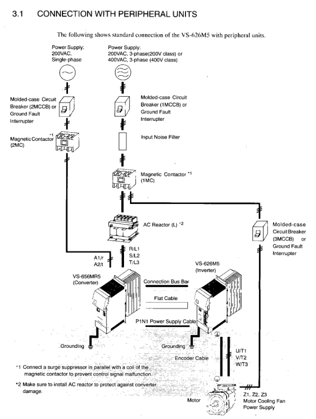
Core products: VARISPEED-626M5 vector control frequency converter (Model: CIMR-M5) and VS-656MR5 power regeneration converter (Model: CIMR-MR5A), specially designed for high-precision motor drive of industrial equipment such as machine tools, supporting power regeneration function and better energy efficiency.
Voltage and power range:
200V level: frequency converter 5-50HP (3.7-37kW), converter 5-50HP (3.7-37kW, 7-60kVA);
400V level: frequency converter 7.5-60HP (5.5-45kW), converter 7.5-60HP (5.5-45kW, 9-70kVA).
Model naming convention: Taking CIMR-M5A27P5 as an example, "CIMR" is the series prefix, "M5" represents VS-626M5 frequency converter, "A" represents independent system use, "2" represents 200V level, "7P5" represents 7.5HP (5.5kW), and the suffix includes the structural type (0=open chassis type, 5=externally cooled heat sink type) and version number.
2. Core performance parameters
Control method: Sine wave PWM vector control, supporting speed control, torque control, and servo mode switching.
Speed regulation performance: The speed regulation range is from 40r/min to the maximum speed of the motor (up to 8000r/min), with a speed accuracy of ≤ 0.2% (rated speed).
Overload capacity: 120% rated current of frequency converter/1 minute; Converter 120% rated current/1 minute, 200% rated current/1 second.
Environmental adaptability: working temperature 0-55 ℃ (inlet temperature of heat sink ≤ 45 ℃), storage temperature -20-60 ℃, humidity ≤ 95% (no condensation), altitude ≤ 1000m, pollution level 2 environment.
Safety operation standards
1. Classification of safety warnings
Warning: Refers to the risk of fatal or serious personal injury, such as not cutting off power before wiring, operating with open covers, touching high-voltage terminals, etc.
CAUTION: May cause minor injury or equipment damage, such as unauthorized installation, incorrect parameter modification, failure to ground according to specifications, etc.
NOTE: Key operation tips to ensure the normal operation of the device, such as wiring spacing, heat dissipation requirements, etc.
2. Key safety requirements
Power off operation: Before wiring or maintenance, the power must be cut off and the capacitor must be discharged for 5 minutes (after the LED is turned off).
Grounding specifications: 200V level grounding resistance ≤ 100 Ω, 400V level ≤ 10 Ω, independent grounding (not shared with high current equipment such as welding machines and motors).
Installation restrictions: It is strictly prohibited to install on flammable materials. A heat dissipation space must be reserved and an external emergency stop circuit must be equipped.
Prohibited behaviors: Do not modify the product structure, do not connect AC power to the output terminals (U/T1, V/T2, W/T3), and do not conduct voltage withstand tests.
Receiving and unboxing inspection
1. Key inspection points
Model verification: Confirm that the equipment model is consistent with the order, and check the nameplate (including input/output specifications, serial number, weight, etc.).
Appearance and components: Check that the shell is not damaged during transportation, screws and connectors are not loose, and components are not missing.
Exception handling: If there is any damage or discrepancy, immediately contact the YASKAWA agent and do not install or operate it on your own.
2. Interpretation of key information on nameplates
Input specifications: 200V level frequency converter DC 270-325V, 400V level DC 540-650V (powered by the converter).
Output specifications: 3-phase AC 0-230V (200V level)/0-460V (400V level), corresponding to different capacities depending on the model (such as 12.9kVA).
Other identification: PROM version number, serial number (for after-sales traceability), structural type (open/cooled).
Installation specifications
1. Installation environment requirements
Avoid scenarios: direct sunlight, rain, snow, moisture, oil spills, salt spray, corrosive gases, dust/metal particles, severe vibrations, strong electromagnetic interference (such as welding machines), and near flammable materials (diluents, solvents, etc.).
Temperature control: The ambient temperature should be ≤ 55 ℃, and the inlet temperature of the heat sink should be ≤ 45 ℃. A fan or cooling device should be equipped to ensure heat dissipation.
2. Installation spacing and method
Installation method: Vertical installation (ensuring smooth heat dissipation airflow), fixed on the surface of non combustible materials such as metal.
Distance requirement (external cooling type with heat sink):
Front/back: ≥ 120mm;
Left and right sides: ≥ 5mm;
The cooling wind speed near the heat sink is ≥ 2.5m/s.
Open chassis type: front/back ≥ 150mm, left and right ≥ 50mm; when combining a converter of 11kW or more with a frequency converter of 7.5kW or less, the spacing must meet 28mm (horizontal) and 57mm (vertical).
3. Component identification
Core components of frequency converter (VS-626M5): mounting base, 4 mounting holes, heat sink, upper and lower cover plates, main circuit terminals (P/⊕, N/⊖, etc.), control power input terminal CHARGE LED、 7-segment LED display screen, output terminals (U/T1, V/T2, W/T3), grounding terminals, various signal connectors (51CN, 52CN, 6CN, etc.).
Core components of converter (VS-656MR5): main circuit power input terminals (R/L1, S/L2, T/L3), control power input terminals (A1/r, A2/t), DC output terminals (P/⊕, N/⊖), control power output terminals (P1, N1), grounding terminal CHARGE LED、 7-segment LED display screen.
Wiring specifications
1. Safety prerequisites for wiring
Wiring personnel: must be operated by qualified electricians and familiar with electrical safety regulations.
Power off confirmation: Before wiring, make sure the power is completely turned off to avoid electric shock.
Terminal tightening: Tighten the terminal screws (such as M6 screws 26lb in/2.94N · m) to the specified torque to prevent loosening and fire hazards.
2. Main circuit wiring
(1) Core requirements
Voltage matching: Ensure that the power supply voltage is consistent with the rated voltage of the equipment (200V/400V level distinction).
Component installation:
The main circuit needs to be connected in series with MCCB (molded case circuit breaker) to protect the circuit;
The input end of the converter must be equipped with an AC reactor of corresponding capacity (to improve power factor);
Inductive loads (contactors, relays, etc.) need to be connected in parallel with surge absorbers or diodes, and are strictly prohibited from being connected to the output terminal of the frequency converter.
Prohibited connection: The input terminal must not be connected to phase advance capacitors or surge suppressors, and the output terminal must not be connected to AC power supply, phase advance capacitors, LC/RC filters, or magnetic starters.
(2) Wiring Details
Converter and frequency converter connection: The main circuit DC power supply is connected through a dedicated connection bus (P/⊕ → P/⊕, N/⊖ → N/⊖), with a torque of 4-5N · m; the control power supply is connected through a dedicated cable (P1 → P1, N1 → N1).
Motor connection: The output terminals of the frequency converter (U/T1, V/T2, W/T3) correspond to the U, V, and W terminals of the motor, ensuring that the motor rotates counterclockwise under the forward rotation command (load side perspective), with a wiring length of ≤ 20m.
Grounding treatment: Use grounding wires that comply with electrical standards, with the shortest possible length, and use single point grounding to avoid loop grounding (refer to Fig.11 and 12).
3. Control circuit wiring
(1) Signal type and connector
Control signal: including encoder signal (RS-422A specification), 12 bit digital reference signal, analog speed reference signal (0 ± 10V), sequence input signal (forward rotation, reverse rotation, emergency stop, etc.), fault output signal, etc.
Key connectors:
1CN: Control signal (digital reference, encoder output, etc.);
2CN: Encoder signal input, motor thermistor signal, etc;
6CN: Simulate speed reference, sequence input/output, fault code output, etc;
3CN: Digital operator connection.
(2) Wiring requirements
Separate wiring: Control the distance between the signal line and the main power line to be ≥ 30cm, avoid parallel wiring, and prevent interference.
Cable specifications: Shielded twisted pair cables are used for control signals, and both ends of the encoder signal cable shielding layer are grounded. The cable length is ≤ 20m.
Input method: 12 digit reference and 6CN sequence input support 0V common,+24V common, or external common (requiring 20-26V power supply), wired according to Fig.13 specifications.
4. Wiring inspection
Inspection items: Wiring correctness (refer to the connection diagram), terminal tightness, bare wire without contact with other terminals, no wire debris or screw residue in the equipment, and it is strictly prohibited to use the control circuit buzzer for inspection.
Operation process
1. Operation mode
Online operation mode: Execute user programs and I/O operations, RDY and RUN LEDs light up, ALM and ERR LEDs turn off when there are no faults.
Offline stop mode: Program stops, output reset, RUN/RDY LED off (trigger scenario: no scan time set, memory not initialized, serious fault, etc.).
2. Start the process
Complete module installation and battery connection (connect CPU battery separately);
Set CPU memory initialization through DIP switch;
Connect CP-717 programming tool;
Load user program;
Start running, the device performs self diagnosis (memory, ROM, CPU function testing).
3. Test Run
Preparation before operation: Clear operational obstacles, notify surrounding personnel, and confirm safety.
Power startup sequence: First turn on the control power supply (or turn it on simultaneously with the main circuit power supply), then turn on the main circuit power supply; The order of closure is reversed.
Status confirmation:
Control power on: converter 7-segment LED displays "- u", frequency converter displays "- b";
Main circuit power on: The converter display switches to "- b", the CHARGE LED red light is on, and the motor cooling fan starts (airflow direction conforms to Fig.16).
Operation: Input the operation signal (FWD/REV), gradually increase the speed reference (starting from 0%), verify the motor rotation (clockwise and counterclockwise), smooth acceleration and deceleration, and no abnormal vibration or noise (kHz level static sound is normal control noise).
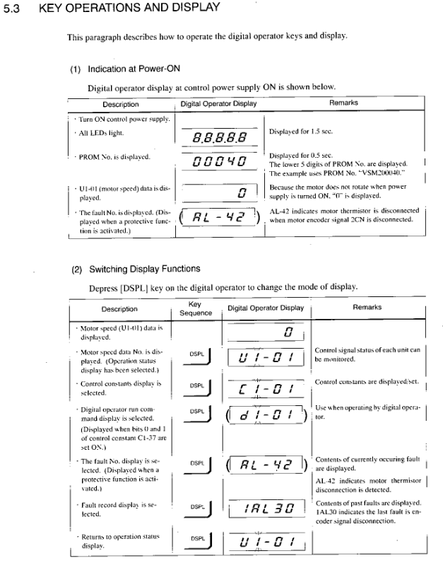
4. Interpretation of 7-segment LED display
Inverter display:
- b ": No running instruction (base block);
- r ": Running;
Fault display: alternately display the fault number and fault code (such as "2-42" indicating that the second fault is the disconnection of the motor thermistor).
Converter display:
- u ": The main circuit is not powered on or under voltage;
- b ": Not running;
Fault display: alternately display the fault number and fault code (such as "1-01" indicating that the first fault was overcurrent).
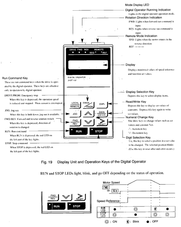
Digital operator (JVOP-132) operation
1. Installation and safety
Installation: Connect through a 3CN connector, use a dedicated extension cable (72616-W5301/5303), tighten the connector screws, and install the cable fixing bracket to prevent detachment.
Safe operation: Before disassembly, the power must be turned off and the capacitor discharge must be completed (LED off).
2. Core functions
Status monitoring: Display operating parameters such as control signal status, motor speed, output current, etc. (refer to APPENDIX 5).
Parameter settings: View and modify control constants (such as speed proportional gain, rated speed, etc., refer to APPENDIX 6), some parameters (C1-25 to 59, etc.) need to be stopped for modification.
Fault handling: Display current fault codes and historical fault records (up to 6), support fault reset.
Independent operation: No external sequence input or speed reference is required, and testing operations such as jogging, forward and reverse rotation can be achieved through the operator (with parameters set to C1-37).
3. Key operations
Mode switching: Press the [DPL] key to switch between operating status display, control constant display, fault display, and other modes.
Parameter modification: Select the constant number → Press the [DATA] key to view the current value → Modify the value → Press the [DATA ENTER] key to write (display "End" for confirmation).
Fault reset: Press the [RESET] key in fault display mode, and before resetting, turn off the external operation command (FWD/REV/ORT).
Maintenance and Inspection
1. Key points for regular maintenance
Daily inspection: tighten terminal screws, clean modules (heat sinks, circuit boards), and check wiring integrity.
Regular inspection (Table 18):
External terminals, mounting bolts, connectors: no looseness;
Heat sink: no dust accumulation (blown with 4-6kg · cm ⁻ ² dry compressed air);
Printed circuit board: no conductive dust or oil stains (replace if unable to remove);
Cooling fan: No abnormal noise or vibration, needs to be replaced after 20000 hours of operation;
Smooth capacitor: no discoloration or odor (5-year inspection, replace if necessary);
Motor bearings: No abnormal noise or temperature rise, maintained for 12000 hours or 2 years.
2. Component replacement cycle (guide)
Remarks on component replacement cycle
Cooling fan (frequency converter/inverter) to be replaced with new parts within 2-3 years
After a 5-year inspection, decide whether to replace the smoothing capacitor
Determine whether to replace the aluminum electrolytic capacitor on the circuit board after a 5-year inspection
Replace the fuse with a new one after 10 years
Motor bearings require 12000 hours or 2 years of disassembly, maintenance, or replacement
Replace the motor cooling fan with a new one after 15000 hours or 2 years
Contact YASKAWA agent for equipment overhaul of 20000 hours or 5 years
3. Maintain safety regulations
Power off requirement: Cut off the main circuit and control power before maintenance, and confirm that the CHARGE LED and 7-segment LED are turned off (capacitor discharge completed).
Operation restrictions: Only authorized personnel are allowed to operate. Remove metal items such as watches and bracelets, use insulated tools, do not touch CMOS components (which are susceptible to static electricity damage), and do not plug or unplug cables/connectors with power on.
- YOKOGAWA
- Reliance
- ADVANCED
- SEW
- ProSoft
- WATLOW
- Kongsberg
- FANUC
- VSD
- DCS
- PLC
- man-machine
- Covid-19
- Energy and Gender
- Energy Access
- Renewable Integration
- Energy Subsidies
- Energy and Water
- Net zero emission
- Energy Security
- Critical Minerals
- A-B
- petroleum
- Mine scale
- Sewage treatment
- cement
- architecture
- Industrial information
- New energy
- Automobile market
- electricity
- Construction site
- HIMA
- ABB
- Rockwell
- Schneider Modicon
- Siemens
- xYCOM
- Yaskawa
- Woodward
- BOSCH Rexroth
- MOOG
- General Electric
- American NI
- Rolls-Royce
- CTI
- Honeywell
- EMERSON
- MAN
- GE
- TRICONEX
- Control Wave
- ALSTOM
- AMAT
- STUDER
- KONGSBERG
- MOTOROLA
- DANAHER MOTION
- Bentley
- Galil
- EATON
- MOLEX
- Triconex
- DEIF
- B&W
- ZYGO
- Aerotech
- DANFOSS
- KOLLMORGEN
- Beijer
- Endress+Hauser
- schneider
- Foxboro
- KB
- REXROTH
- YAMAHA
- Johnson
- Westinghouse
- WAGO
- TOSHIBA
- TEKTRONIX
- BENDER
- BMCM
- SMC
- HITACHI
- HIRSCHMANN
- XP POWER
- Baldor
- Meggitt
- SHINKAWA
- Other Brands
- UniOP
- KUKA
- IBA
- Beckhoff
-
LTI Servo-One Junior SO22.006.0080.1000.0 - Servo Controller Servoregler
-
LUST CDA32.004, C1.4, H08, B0 - Servo Drive & LTI CM-CAN1 Module
-
LTI DRIVES LSP08-035-320-30-B0R1PY170 - Servo Motor
-
LUST LTI CDA32.004,C1.4.H08.B0 - SERVO CONTROLLER DRIVES
-
LUST LTi DRiVES CDS44.072LC1.2 - Servo Drive
-
Lti Servo-One Junior SO22.006.0082.1000.0 - Servo Controller Servoregler
-
LUST CDA32.008,C2.0,HF - Lti DRIVES Spindle Drive Inverter
-
LTI SO22.003.0082.0000.0 - Servo Drives One junior Servo Controller Servoregler
-
Lust Lti Drives CM-CAN1 - Communication Module
-
LUST Lti Drives Vf1202s, G8, I6 - Frequency Inverter Drive
-
LTI DRIVES BR-090.03.540.UR.H38 - Bremswiderstand Brake Resistor
-
LTi DRIVES PM-E40.2DRA054P - Wind Turbine Pitch Control Inverter
-
LTi Drives GmbH br-110.01.540-UR - Brake Resistor
-
LTI Drives LSN-097-0960-30-0560/T1,S4,B - Servo Motor
-
LUST CDA34.006.C2.0 - LTI Drives Servoregler
-
LUST LTI DRIVES SERVO ONE JUNIOR SO24.002.0020.0000.1 - Servo Drive Controller
-
LTI MOTION SO84.032.0003.0001.2 - Servo drives
-
LTI DDTD750V2-120 - IBOP ACTUATOR CYLINDER FOR TOP DRIVE
-
LTI CDE32.004, C2.4 - SERVO DRIVE
-
LUST LTI DRIVES CDD34.017 W3.4PC1 - Servo Drive Controller
-
LTI CDA3208,C3,0,HF - AC SERVO DRIVE
-
LUST LTI DRIVES LSH-074-3-30-560/T1,G6.1S - SERVO MOTOR
-
LUST Lti CDB32.004.C2.4.SH - AC Servo Drive
-
LTi CDA32.006, C3.0, H09 - Servo Drive
-
LTI SO22.003.0010.0000.0 - Servo Drive Servo one junior Servoregler Controller
-
LTi Drives DSM4-14.2-21R83-200 - Servo Motor
-
LUST Lti Drives Lsh-097-1-30-560/T1, 1R - Servomotor
-
LTI 1237 - 7 Piece 1/2" Drive Flip Socket Set
-
LTI Drives CDE34.008.W2.4 - Servo Drive
-
Lust LTi Drives SO84.008.1020.0070.1 - Servo One Drive
-
LTI DRiVES LSP06-015-320-30-00H1MY 170 - Servomotor
-
LUST LTi CDF30.008.C2.4 - Drives Inverter
-
Lust LTI Drives CDA34.017.C2.CP - Servo Controller
-
LUST CDA32.008,C1.4,HF - Lti DRIVES Spindle Drive Inverter
-
LTI Drives LSP08-028-320-55-B0H1MY17W - Sevomotor
-
LTI Motion SO84.032.0173.0100.1 - Servo Drive
-
LTi DRIVES LR32.8 0925.0018 - Einphasen-Netzdrossel Line Choke
-
LTI CDB34.006,W3.0,PC1,H39 - Servo Drive
-
LUST LTI Drives ALW80 BR-200.02,540,UR - R茅sistance Brake Resistor
-
LTi REENERGY Motion E230 G360 /1,2 BWrg-CFpu - Frequency Inverter Drive Controller
-
Lust CDB32.003,C2.4 - LTi Drives Servoregler Frequenzumrichter
-
LTi DRIVES BR-026.03.540-UR - Brake Resistance
-
Lust LTI DRIVES CDA32.006, C3.0, H09 - Frequency Inverter
-
LUST LTi Drives CM-CAN1 - Communication Module
-
LTI DRIVES lsn-127-2000-30-560/t1,s4x,b - Servomotor
-
LUST LTI Drives CDA34.017.C2.CP - Servoregler
-
LTi DRIVES SO84.016.1030.0000.0 - Servo one Drive
-
LTI Servo-One Junior SO22.006.0080.1000.0 - Servo Controller Servoregler
-
LUST Lti Drives Lsh-097-1-30-560/T1, 1R - Servomotor
-
LUST Lti Drives Vf1202s, G8, I6 - Frequency Inverter
-
LUST LTI Drives CDB32.003,C2.4 - Servo Drive
-
LTI MOTION SO24.004.0030.0001.1 - Servo drives
-
LUST CDA32.004,C1.4 - LTI Drives Servoregler
-
Lti Drives Lust CDA34.017.W3.0 - Control Unit
-
LUST CDA34.006, W3.0 - Controlador Servoregler LTI Drives
-
LTI Motion SO24-004-0030-1000-0 - Servo One Junior Drive Controller
-
Lust LTi Drives CDE34,010.D2.4 - Positioning Controller
-
Lust LTi Drives CDF30.002 C3.0 - Positioning Controller
-
LTI SO22.003.0080.0000.0 - Servo Controller Servo Regulator
-
LUST LTi CDB32.004,C2.4.SH - SERVO DRIVE
-
LTI DRiVES LSP06-015-320-60-B0H1MY170 - Servo Motor
-
LTI MOTION PM-D35.1WVA02 - Drive Module
-
LUST ANTRIESTECHNIK BC1300 - LTI DRIVES Brake Chopper
-
LTi DRIVES BR-090.03.540.UR.H38 - Bremswiderstand Brake Resistor
-
LUST LTi DRiVES CDE32.003,C2.3 - Servo Drive Controller
-
LUST LTI Drives CDA34.017.W2.0.H18 - Servo Drive
-
LTi DRIVES FGP 111/002-25 AA - Servomotor Servo Motor
-
Lti SO22.006.0080.1000.1 - Servo Controller Servoregler
-
LUST Lti Drives Vf1202s,G8,I6 - Frequency Inverter Drive
-
Lust CDA34.008,W1.4,BR - LTi Drives Servo Drive
-
LTi Drives Lust CDA34.017.W3.0 - Steuerungseinheit Control Unit
-
Keba/LTI Drives LSN-127-2400-15-560/T1.B.S4X - Servomotor
-
Drives by Lust LTI CDA34.006 W 1.5 - Frequenzumrichter Frequency Inverter
-
LTI DRIVES lsn-127-2000-30-560/t1,s4,b - Permanent Magnet Motor
-
LUST LTI Drives VF1204S, G10, FA - Frequency Inverter Drive
-
LTi DRiVES SO84.004.1030.0000.2 - Servo Drive
-
LUST CDA34.006, W3.0 - LTI Drives Servoregler Servo Controller
-
Lust CDE32.004,C2.4 - LTI Drives Controller
-
LTI MOTION CDE32.003,C2.4 - Servo Drive Controller
-
LTI CDE32.004, C3.0 - Servo Drive Controller
-
LUST CDA34.006.C2.0 - LTI Drives Servoregler Servo Controller
-
LUST LTI DRIVES LSH-097-2-30-560/T1,S4,G6.1S - Servo Motor
-
Lust Cdb32.003, C2.4 - Lti Drives Servo Controller
-
LTi DRiVES SO84.076.S030.0001.2-W - Servo One Drive
-
LUST LTI Drives CDA34.017.C2.CP - Regulador De Servomotor Servo Controller
-
LUST LTI Drives CDA34.008.C1.3 - Servoregler Servo Controller
-
LUST LTI Drives CDA34.017.C2.CP - Servoregler Servo Controller
-
Lust LTi Drives CDB32.003C2.3 - Servoregler Servo Controller with LTi UM-8I40 Module
-
LTI D-35633 - Servo Drive
-
LTi Drives Lust CDA34.017.W3.0 - Steuerungseinheit Control Unit
-
Lti SO22.003.0082.0000.0 - Servo Controller Servoregler
-
LTI Tools LT-1400Q - 1/2" Drive Wheel Torque Extension Tool
-
LTI CDE32.003-C3.0 - Servo Drive Controller
-
LTI CDA32.004 - Servo Drive
-
Lust Lti Drives CDB32.008, C2.3 - Servo Controller
-
LUST LTi Drives SO82.004.0030.0060.2 - Servo Drive
-
Lust LTI DRiVES CDA32.006,C3.0,H09 - Servo Drive
-
LUST LTI Drives CDA34.003. C3.0 - Servo Controller
-
LTI Motion CDE32.003.C2.4 - Servo Drive Positioning Controller
-
LTI CDB32.004.C3.7.SH - Servo Drive
-
LTI DRIVES VF1202S - Frequency Inverter Drive
-
LTI DRIVES GMBH LR34.44-UR - Line Choke Reactor
-
LUST LTi DRIVES LSH-097-1-30-560/T1,1R - Servo Motor
-
LTI DRIVES LSH-127-3-30-560 - Servomotor
-
LUST CDA32.008,C1,4,HF - LTi Spindle Drive Inverter
-
LUST LTI Drives CDA34.017.C2 - Servoregler Servo Controller with LUST LTI CM-DPV1,3.0 Modul
-
LTI DRIVES CM-DPV1,3.0 - Input Drive Communication Module
-
LTI CDE34.005,W2.4 - Servo Drive
-
Lust Lti Drives Cda32.008.C2.0,Hf - Servo Drive Spindle Inverter
-
LUST CDA34.006,W3.0 - LTI Drives Servoregler Servo Controller
-
LUST ANTRIESTECHNIK LR32.8 -- 0925.0018 - LTI DRIVES Choke Reactor
-
LUST LTI Drives CDA32.008,C3.0 - Servo Drive
-
LUST LTi DRIVES CM-DPV1 3.0 - Communication Module
-
LUST Lti Drives CDA34.008.C1.3 - Servoregulador Servo Controller
-
LTI DRIVES GMBH SO84.008.0020.0000.2 - Servo One Drive
-
LUST CDA34.006,W3.0 - LTI Drives Servoregler Servo Controller
-
LUST LTI DRIVES CDE32.003,C2.3 - Servo Drive Controller
-
LTI CD32.004 C3.0 AND CM-CAN1 - Servo Drive with Communication Module
-
LTI Motion CDE32.003.C3.0 - Servo Drive Positioning Controller
-
LUST SO84.012.0030.1700.2 - LTi Drives Servo Drive
-
LUST LTI Drives CCD34.024.W2.1.BR - Servo Drive with CM-CAN2 Communication Module
-
Lust CDA34.006.C2.0 - LTI Drives Servoregler Servo Controller
-
Lust Lti Drives VF1202S, G8, I6 - Frequency Inverter Drive
-
Lust LTi Drives CDE32.008,W2.2.BR - Positionierregler Position Controller
-
LTi DRiVES LSH-050-3-45-320/T1,S4,1R - Servomotor
-
LUST LTI Drives CDA34.006,W1.5,BR - Inverter with CM-RS485 Module
-
LUST ANTRIESTECHNIK VF1204S,G10,FA - LTI DRIVES VFD Variable Frequency Drive
-
Lust LTi Drives CDB32.008,C2.3 - Servoregler Servo Controller

K-JIANG

Add: Jimei North Road, Jimei District, Xiamen, Fujian, China
Tell:+86-15305925923