
K-WANG


Tektronix TPS2000 series digital storage oscilloscope
Tektronix TPS2000 series digital storage oscilloscope
Overview
The official guide document for the Tektronix TPS2000 series digital storage oscilloscope covers the 2-channel (TPS2012) and 4-channel (TPS2014/TPS2024) models, with a core positioning for portable isolation measurement scenarios (such as industrial equipment floating ground testing and outdoor on-site maintenance). The document structure is clear, gradually deepening from safety specifications to advanced functions, including 11 core chapters and 6 appendices, catering to both novice operation and professional measurement needs, while providing rich diagrams and step instructions to reduce operational complexity.
Core parameters and characteristics of the product
1. Model classification and key parameters
Model Number of Channels Bandwidth Sampling Rate Single Battery Endurance Dual Battery Endurance
TPS 2012 2 100MHz 1GS/s 5.5 hours 11 hours
TPS 2014 4 100MHz 1GS/s 4.5 hours 9 hours
TPS2024 4 200MHz 2GS/s 4.5 hours 9 hours
2. Core Features
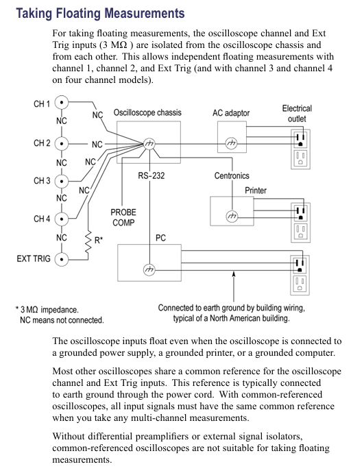
Isolation channel: All channels and Ext Trig inputs are isolated from chassis, supporting independent floating ground measurement with an input impedance of 3M Ω, solving the common ground limitation of traditional oscilloscopes;
Portable power supply: compatible with TPSBAT lithium batteries (standard 1, optional 2), can be charged simultaneously when powered by mains electricity;
Full function analysis: supports peak detection (capturing ≥ 10ns glitches), video triggering (NTSC/PAL/SECAM), FFT spectrum analysis (2048 point transform);
Data interface: Front mounted Type 1 CompactFlash card slot, rear mounted RS-232 (9-pin) and Centronics (parallel printing) interfaces.
Safety operation standards
1. Electrical safety
Voltage limitation: The maximum voltage of the input channel is 300V RMS CAT II. When it exceeds 100kHz, it will attenuate by 20dB/tenfold to avoid arc damage;
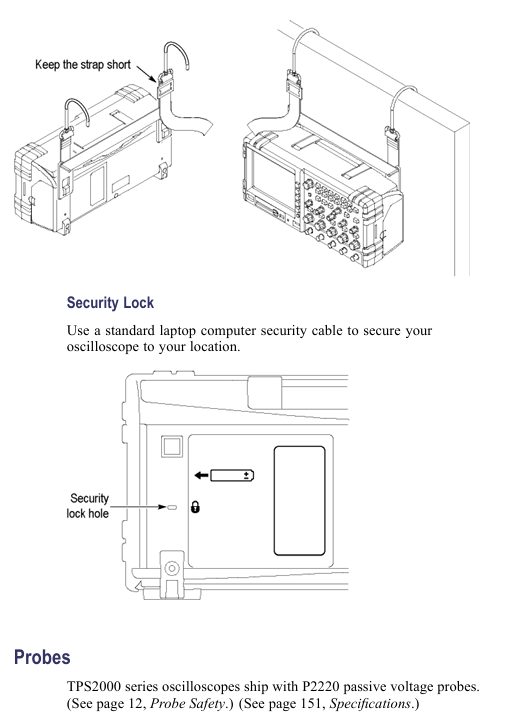
Probe safety: The reference end of the P2220 probe is prohibited from floating above 30V RMS. For high voltage measurements, P5120 (600V RMS CAT II) or differential probes are required;
Grounding requirements: A 3-pin power cord must be used and disconnection of the grounding is prohibited; The equipment chassis needs to be reliably grounded to avoid electric shock caused by floating operations.
2. Operation taboos
Prohibit use in damp/explosive environments and avoid liquid spraying equipment;
Before connecting/disconnecting the probe, the signal source must be disconnected first, and live operation is prohibited;
Before disassembling the battery, it is necessary to turn off the device and avoid short circuiting the battery contacts or putting them into a fire.
Basic operation process
1. Probe operation
Key requirements for operation type steps
Manual compensation: 1. Connect the probe to CH1 and set it to 10X; 2. Connect it to PROBE COMP; 3. Autoset; 4. Adjust the compensation hole to a square wave that is flat and free of dents/bulges. Re compensate each time the channel is changed
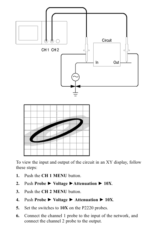
Attenuation setting 1. Press CHx MENU → Probe → Voltage Attenuation; 2. Choose 1X/10X P2220 and set the bandwidth limit to 6MHz for 1X
Current probe scaling 1. Press CHx MENU → Probe → Current → Scale; 2. Choose a matching value (such as 10A/V) to ensure consistency with the output ratio of the current probe and avoid reading deviation
2. Self calibration and firmware updates
Self calibration:
Disconnect all probes and press 【 Utility 】 → 【 Do Self Cal 】;
Wait for 2 minutes, and upon completion, display 'Calibration PASSED';
Trigger condition: If the environmental temperature difference exceeds 5 ℃ or once a week, preheating for 20 minutes is required.
Firmware update:
Download the latest firmware from the official website and copy it to the root directory of CompactFlash;
Insert the oscilloscope and press 【 Utility 】 → 【 File Utilities 】 → 【 Update Firmware 】;
Wait for completion, do not power off or unplug the card.
Core Systems and Functions
1. Collection system (three modes)
The working principle of the collection mode is applicable to different scenarios
Sampling mode equidistant sampling, 1-point/interval conventional stable signal (sine wave/square wave)
Peak detection mode records the maximum/minimum values of each interval, including signals with spikes and narrow pulses (≥ 10ns)
After multiple acquisitions in average mode, the signal containing random noise (power ripple, sensor output) is averaged (4/16/64/128 times)
2. Trigger system (three types)
Trigger type key parameters applicable scenarios
Edge triggered slope (rising/falling), coupling (AC/DC/noise suppression), stable display of conventional signals (such as clock signals)
Video trigger standards (NTSC/PAL/SECAM), synchronous (field/line) composite video signals (such as medical equipment video output)
Pulse width triggering condition (=≠<>), width (33ns-10s), polarity capture abnormal pulse (such as communication link narrow pulse interference)
3. FFT spectrum analysis
Setting steps:
Center the time-domain signal (align the 0V line with the center of the screen) to ensure complete waveform;
Press Math Menu → Operation → FFT to select the source channel;
Window selection function (Hanning window: excellent frequency resolution; flat top window: excellent amplitude accuracy).
De aliasing method:
Increase sampling rate (switch from SEC/DIV to faster gear);
Enable 20MHz bandwidth limit;
External filtering (adding a low-pass filter at the signal source end).
Battery Management (Core Features)
1. Charging and battery life
Charging method: single battery charging time, dual battery charging sequence, battery life (4-channel model)
In machine (power on), charge the high battery first for 7 hours, then charge the low battery for 4.5 hours (single battery), and 9 hours (dual battery)
In machine (standby) 4.5 hours as above-
External TPSCHG charger can charge 2 units simultaneously in 3 hours-
2. Calibration and maintenance
Calibration:
External calibration: TPSCHG charger left slot → press "Recalibrate", takes about 10 hours (charge discharge cycle);
In machine calibration: discharge to shutdown → charge for 5 hours → discharge to shutdown → recharge for another 5 hours.
Storage:
Temperature: 5-20 ℃, humidity ≤ 80%;
Electricity consumption: about 50%, replenished once every 6 months;
Taboo: Long term full charge (>80%) or empty charge (<20%) storage is prohibited.
Data Storage and Communication
1. CompactFlash card operation
Storage Content File Name Format 1MB Capacity Approximately Storage Quantity Key Operations
18 waveform files FnnnnCHx.CSV, press 【 Save/Recall 】 → 【 Save Waveform 】 → Select Channel
Set file FnnnnTEK.SET to 250, press 【 Save/Recall 】 → 【 Save Setup 】 → select storage location
16 image files FnnnnTEK.BMP, press [Print] (set to "Save Image to File")
2. RS-232 communication settings
Parameter configuration: Press 【 Utility 】 → 【 Options 】 → 【 RS232 Setup 】 to set the baud rate (default 9600), flow control (Hardtagging), and checksum (None);
Test steps:
Connect the oscilloscope to the PC using cable 012-1379-00;
Open HyperTerminal on the PC and set the same parameters;
Send 'ID?', the oscilloscope returns' ID TEK/TPS2024, CF: 91.1CT, FV: V10.00 '.
Typical application cases
1. Isolation channel measurement differential signal
Connect the probe tip to the positive terminal of the differential signal and the reference terminal to the negative terminal (no common ground required);
Press' AutoSet 'to display the differential waveform;
Press' Single Seq 'to capture a snapshot, and use the cursor to measure the amplitude/rise time.
2. Video signal triggering (NTSC)
Connect the probe to video output, press 【 CH1 MENU 】 → 【 Coupling 】 → 【 AC 】;
Press 【 Trig Menu 】→【 Type 】→【 Video 】→【 Standard 】→【 NTSC 】;
Select [Sync] → [All Lines], adjust SEC/DIV to 500ns/div, and observe the color synchronization signal.
3. Power waveform measurement (voltage x current)
CH1 connected to voltage probe (10X), CH2 connected to current probe (10A/V);
Press 【 Math Menu 】→【 Operation 】→【 × 】→【 CH1 × CH2 】;
Adjust the Math waveform position/scale to display instantaneous power (in VA).
Appendix and Support
1. Key performance parameters
System parameter description
Vertical system resolution 8-bit, 2mV-5V/div
Horizontal system time base range TPS2024:2.5ns-50s/div; TPS2012/2014:5ns-50s/div
Trigger system edge trigger sensitivity DC coupling: 1div (DC-10MHz), 2div (100-200MHz)
Display system resolution of 320 × 240 pixels, 5.7-inch LCD
2. Probe compatibility
Probe model, attenuation ratio, bandwidth, maximum voltage, applicable scenarios
P2220 (Standard) 1X/10X 6MHz/200MHz 150V/300V RMS CAT II Conventional Voltage Measurement
P5120 (optional) 20X 200MHz 1000V RMS CAT II high voltage measurement
TCP303 (optional) 5/50mV/A 15MHz 150A RMS high current AC/DC measurement
- YOKOGAWA
- Reliance
- ADVANCED
- SEW
- ProSoft
- WATLOW
- Kongsberg
- FANUC
- VSD
- DCS
- PLC
- man-machine
- Covid-19
- Energy and Gender
- Energy Access
- Renewable Integration
- Energy Subsidies
- Energy and Water
- Net zero emission
- Energy Security
- Critical Minerals
- A-B
- petroleum
- Mine scale
- Sewage treatment
- cement
- architecture
- Industrial information
- New energy
- Automobile market
- electricity
- Construction site
- HIMA
- ABB
- Rockwell
- Schneider Modicon
- Siemens
- xYCOM
- Yaskawa
- Woodward
- BOSCH Rexroth
- MOOG
- General Electric
- American NI
- Rolls-Royce
- CTI
- Honeywell
- EMERSON
- MAN
- GE
- TRICONEX
- Control Wave
- ALSTOM
- AMAT
- STUDER
- KONGSBERG
- MOTOROLA
- DANAHER MOTION
- Bentley
- Galil
- EATON
- MOLEX
- Triconex
- DEIF
- B&W
- ZYGO
- Aerotech
- DANFOSS
- KOLLMORGEN
- Beijer
- Endress+Hauser
- schneider
- Foxboro
- KB
- REXROTH
- YAMAHA
- Johnson
- Westinghouse
- WAGO
- TOSHIBA
- TEKTRONIX
- BENDER
- BMCM
- SMC
- HITACHI
- HIRSCHMANN
- XP POWER
- Baldor
- Meggitt
- SHINKAWA
- Other Brands
- UniOP
- KUKA
- IBA
- Beckhoff
-
ADLINK CPCI-6860A - 51-31310-OB10 industrial motherboard CompactPCI SBC
-
ADLINK AmITX-SL-G-H110 - 51-7A104-0A30 Mini-ITX Industrial Motherboard
-
ADLINK PXI-2005-003 - CPCI Industrial PC Data Acquisition Card Multi-Function DAQ
-
ADLINK DININ-814M - 51-14032-0A3D SCSI-100P cable connection Interface Terminal Board
-
ADLINK CPCI-3920NA/C2D15/M1G - 3U CompactPCI Intel Core 2 Duo Single Board Computer
-
ADLINK PCIE-8560 - 51-18014-0A20 Communication Card High Speed DAQ
-
ADLINK PCI-C154+ - Motion Control Card 4-axis Motion Controller Board
-
ADLINK PCI-RTV24 - image capture card Analog Video Frame Grabber
-
ADLINK NuPRO-842LV/P - 51-41360-0B30 Industrial Motherboard CPU Board
-
ADLINK cBP-3208/3208R - CPCI Board 3U 8-Slot CompactPCI Backplane
-
ADLINK PCI-8164 - 4-Axis Motion Controller PCI Card 51-12406-0A40
-
ADLINK PCIe-GIE64+ - 4-CH GigE Vision PoE+ Frame Grabber Video Capture Card
-
ADLINK CPCI-6860 / 6860A - CompactPCI Dual Xeon Single Board Computer
-
ADLINK IEC-915GV - REV 1.1 Industrial motherboard CPU Board
-
ADLINK ND-6520 - Technology RS-232 to RS-422RS-485 Converter NuDAM Module
-
ADLINK RTV-24 / PCI-MP4S - 51-12519-1C30 4-Channel Real Time Video Capture Board
-
ADLINK cPCI-6910 / cPCI-6910AM/M1G - cPCI-6910AM/DXL16/M1G/S80G(G)-3120 BOARD CompactPCI SBC
-
ADLINK NUPRO-A40H - Linghua 51-41807-1A30 Industrial Control Computer Motherboard
-
ADLINK USB-3488A - USB to GPIB INTERFACE USB-3488A(G) Controller Module
-
ADLINK PCI-8134A - motion control card 4-Axis Controller Card
-
ADLINK PCI-7432 - Board 32-Channel input / 32-output Isolated Digital I/O PCI Card
-
ADLINK PCI-8134A - 51-12421-0A10 motion controller card tested
-
ADLINK LPCIe-7230 - 32 CH Isolated Input/output Card 2 Interrupts Low Profile PCIe
-
ADLINK NuPRO-E340 - industrial computer motherboard 51-47807-0A30 PICMG 1.3 SHB
-
ADLINK PCI-7434 - High-speed Digital Acquisition Card 64-CH Isolated DO Card
-
ADLINK NuPRO-E330 - 51-41805-0A20 Indsutrial Board SHB Single Board Computer
-
ADLINK PCI-7248 - OPTO-22 48 CHANNEL DIO DIGITAL TTL/DTL I/O 51-12006-0A40 GP
-
ADLINK PCI-8134 - Motion control card 4-Axis Controller Card
-
ADLINK AMP-208C - Movimiento Control Tarjeta 51-12420-1A20 W/Expansión & Breakout
-
ADLINK PCI-8164 - 51-12406-0A40 PCB Board 4-Axis Motion Controller Card
-
ADLINK DIN-68Y-SGII / DIN-68M-J3A - Terminal Board Connector Interface Block
-
ADLINK PCIe-7432 - Technology 51-18402-0A10 PCIe Card With High Input Range
-
ADLINK PCI-8144 / PCI-8144N - Motion control card 4-Axis Stepper Controller Card
-
ADLINK HSL-HUB3/REPEATER - HIGH SPEED LINK EXTENSION MODULES Distributed Hub Module
-
ADLINK ND-6017 - Data Logging + Acquisition 8CH A/D input Mod NuDAM Module
-
ADLINK LPCIe-7250 - data acquisition card Low Profile 8-CH Relay Output Card
-
ADLINK PCI-7432 - I/O card 64-CH Isolated Digital Input Output PCI Card
-
ADLINK IMB-M43H - industrial control computer motherboard Q87 Chip Micro-ATX
-
ADLINK MP-C154 - Motion control Card 4-Axis Motion Controller Board
-
ADLINK PCI-RTV24 - image capture card Video Frame Grabber Card
-
ADLINK PCI-7250 - 8-CH Relay Output & 8-CH Isolated DI Card
-
ADLINK PCI-6308V - 8-CH 12-Bit Isolated Analog Output PCI Card PCB-I-E-1148=6EX2
-
ADLINK PCI-7248 - capture card 48-CH Opto-22 Compatible DIO Card
-
ADLINK HSL-AI16A02-M-VV - Analog Input Output Distributed Module
-
ADLINK NuPRO-A301 - Rev:1.4 NUPRO-A301 PICMG Full-Size Single Board Computer
-
ADLINK PCI-6208V-GL - 8-CH Voltage Analog Output PCI Card
-
ADLINK PCI-8134A - 51-12421-0A10 4-Axis Motion Controller Card
-
ADLINK MNET-S23 - TECHNOLOGY MNET S23 - SERVO DRIVER CONTROL MODULE
-
ADLINK M-342 - ATX I3 I5 I7 Q67 Industrial Motherboard
-
ADLINK NUPRO-780 - Industrial Motherboard CPU Board PICMG SBC
-
ADLINK MP-C154 / MP-C152 - 4-Axis Motion Control Card Pulse-Train Controller
-
ADLINK NuPRO-935A/LV10B0 - Motherboard 51-41802-0A10 GP w/RAM Industrial Control Board
-
ADLINK MP-C154 - Motion control card 4-Axis Motion Controller Mainboard
-
ADLINK PCI-7250 - PCI Acquisition Card 8-CH Relay Output Isolated DI Card
-
ADLINK ACL-7124 - Technology Inc.24 DIO Card Digital Input Output Card
-
ADLINK PCI-8554 A2 - Timer/Counter Data Acquisition Card
-
ADLINK DIN-825-GP4 - Terminal Block Interface Board Breakout Module
-
ADLINK NuPR0-761 - REV:1.1 Industrial motherboard Full-Size PICMG SBC
-
ADLINK MXE-1401/M8G (G) - Matrix Fanless Embedded Computer Industrial PC
-
ADLINK HSL-DI16DO16-UD-NN - Digital 16 Channel I/O Mod Distributed I/O Module
-
ADLINK ND6520 - NUDAM INTELLIGENT DA&C MODULE RS232-RS-422/RS485 CONVERTOR
-
ADLINK NUPRO-761 - REV:1.1 Industrial Motherboard CPU Board
-
ADLINK AMP-208C - Motion Control Card 51-12420-1A20 DSP-based 8-axis
-
ADLINK NuPRO-A301REV 1.4 - with packaging industrial computer motherboard PICMG SBC
-
ADLINK PCM-9112+ - 51-12300-0A2 industrial motherboard Multi-Function DAQ PC/104 Module
-
ADLINK PCM-7250+ - 8-CH Relay Outputs & 8-CH Isolated DI Module PC/104
-
ADLINK PCI-RTV24 - Image capture card Analog Video Frame Grabber
-
ADLINK PCI-8134 - Motion Controller PCI Card 4-Axis Controller Board
-
ADLINK PCI-7432 - Isolated Digital I/O PCI Card
-
ADLINK PCI-8554 A2 - acquisition card Timer/Counter Card
-
ADLINK PCI-8132 - Rev.A2 2-Axis Servo & Stepper Motion Controller Card
-
ADLINK PCI-8132 - Data Acquisition card 2-Axis Motion Controller Card
-
ADLINK EBP-13E4 - 51-46703-0A30 Industrial Backplane Board Passive Backplane
-
ADLINK PCI-800L - Electronic Card Interface Controller Card
-
ADLINK PCIe-GIE72 - 51-18531-0A10 PCB Board GigE Vision Frame Grabber
-
ADLINK DAQ-2010(G)-OOBO - Simultaneous-Sampling Multi-Function DAQ Card
-
ADLINK PCI-9112 - REV.B1 Multifunction DAQ Card Data Acquisition Card
-
ADLINK PCI-7230 - 51-12003-DA60 32-CH Isolated Digital I/O Card
-
ADLINK PCI-7432 - Data Acquisition Card Isolated Digital I/O PCI Card
-
ADLINK ETX-AT-N270-18/LXE - 51-71111-0A20 ETX CPU Module Motherboard
-
ADLINK HSL-DI32-UD-N - DIGITAL INPUT 32 POINTS MODULE Distributed I/O
-
ADLINK AMP-204C - Motion Control card DSP-Based 4-Axis Advanced Controller
-
ADLINK MNET-4XMOG-0050 - Four-axis Motion Controller Distributed Motion Module
-
ADLINK AMP-204C - Motion control card DSP-Based 4-Axis Pulse-Train Controller
-
ADLINK PCI-7442 - Switch card 64-Channel Datalogging & Acquisition Card
-
ADLINK M-302 - Industrial control motherboard ATX PC Board
-
ADLINK NUPRO-852 / NUPRO-852LV - Industrial motherboard Single Board Computer
-
ADLINK PCI-8134 - REV.B1. 4-Axis Motion Controller Card
-
ADLINK PCI-GIE62 + - 51-18502-0A20 2-CH GigE Vision Frame Grabber PoE Card
-
ADLINK PCI-MPG24 - 51-12523-0B20 MPEG4 Card Video Compression Hardware
-
ADLINK HSL-TB32-M-DIN - 32-CH I/O TERMINAL W/ HSL-AI16AO2-M-VV MODULE
-
ADLINK PCI-M114-GL - PCB Ver 2.1 Motion Controller Axis Card
-
ADLINK IMB-M40H - SYM76996H61 motherboard Industrial Computer Mainboard
-
ADLINK NUPRO-A40H - 51-41807-1A20 industrial control motherboard H61 Chip
-
ADLINK PCI-M114-GL - Axis Card Data Acquisition Card PCB VER2.2 Motion Controller
-
ADLINK PCI-8134 - Motion Controller PCI Card 4-Axis Controller Board
-
ADLINK PCI-8102 - Motion control card 2-Axis Servo & Stepper Controller
-
ADLINK NuPRO-841REV:3.0 - motherboard Industrial Control PC Board
-
ADLINK HSL-TB32-U-DIN REV A1 - Breakout Terminal Board Field I/O Module
-
ADLINK AMP-204C - Motion Control card DSP-Based 4-Axis Pulse-Train Controller
-
ADLINK NUPRO-A40H - 51-41807-1A20 industrial control motherboard H61 PC Board
-
ADLINK PCI-6308A / PCI-6308V - 51-12202-0A50 Isolated Analog Output Card
-
ADLINK AMP-204C - DSP-Based 4-Axis Advanced Pulse-Train Motion Controller
-
ADLINK PCI-7434 - Technology 64-Channel Isolated Digital I/O PCI Cards
-
ADLINK CPCI-6840 / CPCI-6840V / PM16/M1G-12G0 - CompactPCI Single Board Computer CPU Module
-
ADLINK PCIE-GIE74 - Motherboard Video Capture Card 51-18531-0A10 Frame Grabber
-
ADLINK NuPRO-E330 - industrial computer equipment motherboard Control Mainboard
-
ADLINK AMP-208C / 51-12420-1A20 - Motion Control Card W/ Expansion & Breakout Board
-
ADLINK HPCI-14S12U - industrial computer baseboard Passive Backplane 14 Slots
-
ADLINK PCI-8164 - 4-Axis Motion Controller PCI Card W/ 1x Cable, 1x Breakout Box
-
ADLINK PCIe-RTV24 - 51-18016-0A20 Image Acquisition Video Capture Card
-
ADLINK M-342 - 5 PCI ATX Motherboard Industrial PC Mainboard
-
ADLINK PCI-FIW64 - 4/2 Channel IEEE1394B Image Capture Card FireWire Frame Grabber
-
ADLINK PCI-7432 - digital IO card 64-CH Isolated Digital Input Output Card
-
ADLINK 51-12001-0C20 - Circuit Board PCI-7200 Data Acquisition Controller Card
-
ADLINK PXI-3920 - PXI 3U cPCI Industrial Controller Embedded System CPU Board
-
ADLINK NuPRO-841REV:2.0 - motherboard Industrial Control PC Board
-
ADLINK NuPro-E330 - 51-41805-0A20 PCB Industrial Control Computer Motherboard
-
ADLINK PCI-RTV24 - Image capture card Analog Video Frame Grabber
-
ADLINK PCI-7442 - Switch card 64-Channel Datalogging & Acquisition Card
-
ADLINK HPX-13S4 - device baseboard Passive Backplane Riser Card
-
ADLINK PCI-9112 REV A.1 - Multi Function DA&C Board Data Acquisition Card
-
ADLINK PCI-7248 - 51-12006-0A40 Card Control 48-CH Digital I/O Module
-
ADLINK CPCI-6860 / 6860A - motherboard CompactPCI Dual Xeon Single Board Computer
-
ADLINK DPAC-3020-11(G) - Embedded PC Automation Controller Machine Control Board
-
ADLINK NuPRO-841 REV:1.0 - industrial control motherboard CPU Board
-
ADLINK MNET-4XMOG-0050 - Four-axis Motion Controller MNET Motion Control Card
-
ADLINK ETX-AT-N270-18/LXE - 51-71111-0A20 ETX CPU Module Motherboard

K-JIANG

Add: Jimei North Road, Jimei District, Xiamen, Fujian, China
Tell:+86-15305925923