

K-WANG


Yokogawa PH4/OR4 series pH and ORP sensor (IM12B10B00-01EN)
Yokogawa PH4/OR4 series pH and ORP sensor (IM12B10B00-01EN)
Product positioning and core series
1. Core positioning
PH4/OR4 series is a special electrochemical sensor designed for different severe working conditions. Through differentiated materials (such as HF resistant glass, perfluoroelastomer), electrolyte type (polymer electrolyte, high viscosity gel) and structure (built-in RTD, pressurized design), the PH4/OR4 series can solve the measurement stability problem of ordinary sensors under strong corrosion, high temperature, high viscosity and other scenarios. At the same time, it is compatible with mainstream transmitters in Yokogawa to meet industrial reliability requirements.
2. Series models and applicable scenarios
The series includes 9 sub models, classified according to measurement parameters (pH/ORP) and adaptability to working conditions. The core differences are as follows:
Model Series Type Core Features Applicable Scenarios
PH4P/PH4PT polymer electrolyte pH sensor with built-in polymer electrolyte (including KCl), no risk of liquid leakage; PH4PT with Pt1000 RTD (temperature compensation); General scenarios (such as municipal sewage and neutral solutions), without the need for frequent electrolyte replenishment;
The PH4F/PH4FT anti HF corrosion pH sensor is made of anti HF glass material, which can withstand low pH (2-11) and HF concentration (≤ 500 ppm at pH 2); PH4FT with RTD; Scenarios containing hydrofluoric acid (such as semiconductor cleaning, fluorine chemical industry);
PH4C/PH4CT special chemical pH sensor has a wide pH range (0~14) and built-in pressurized gel electrolyte (initial 250 kPa) to prevent medium infiltration; PH4CT with RTD; Strong acid-base and high viscosity media (such as chemical reaction vessels and acid-base neutralization processes);
OR4P/OR4C ORP sensor OR4P (polymer electrolyte, platinum wire electrode), OR4C (pressurized gel, platinum ring electrode); OR4P: Universal oxidation-reduction scenarios (such as wastewater treatment and disinfection); OR4C: Pollution prone scenarios (such as sulfide containing solutions);
PH4FE fermentation specific pH sensor long axis design (120/200mm), open electrolyte replenishment port, suitable for deep measurement in fermentation tanks; The biological fermentation process (such as pharmaceutical and food fermentation) requires regular replenishment of electrolytes;
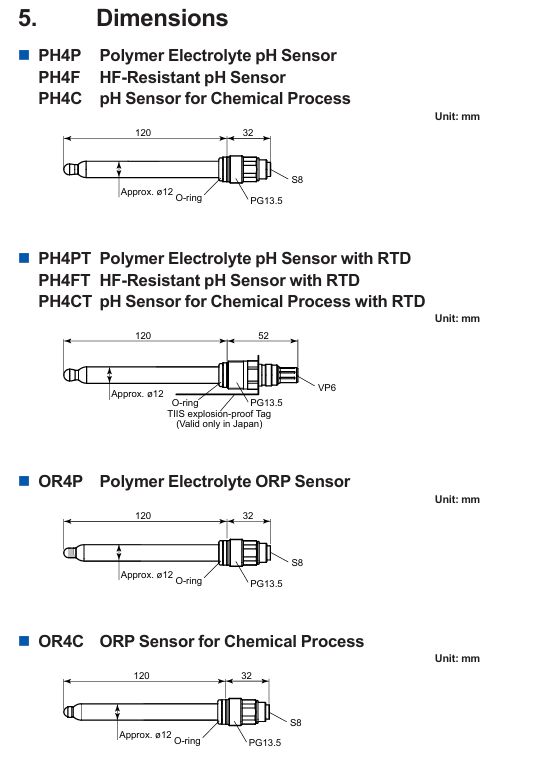
Detailed explanation of technical specifications
1. Basic measurement parameters
Parameter category specification details (taking typical models as examples)
PH measurement range: PH4P/PH4CT 0~14 pH, PH4F 2~11 pH;
Accuracy: Slope ≥ 96% (25 ℃), asymmetric potential ± 15 mV;
Response time: t ₉₀<15 seconds (pH 7 → 4 step);
ORP measurement range: -1500~+1500 mV;
Electrode material: OR4P (platinum wire), OR4C (platinum ring);
Reference system: Ag/AgCl (containing KCl electrolyte);
Temperature adaptation without RTD model: -20~70 ℃ (ambient), process temperature varies from 0~105 ℃ depending on the model;
Model with RTD (such as PH4PT): Built in Pt1000 (-20~200 ℃) for temperature compensation;
Pressure adapted atmospheric pressure model (PH4P/PH4F): maximum immersion depth of 3m;
Pressure model (PH4C/OR4C): Initial pressure of 250 kPa, gradually decreasing with use, to avoid process pressure exceeding the internal pressure of the sensor;
Contact material body: borosilicate glass/HF resistant glass;
Electrolyte: PH4P (polymer), PH4C (high viscosity gel) PH4FE(3M KCl-LR);
Sealing components: Fluororubber (FPM)/Perfluoroelastomer (FFKM, optional/PF);
There is no clear IP rating for protection and installation, and it is necessary to cooperate with brackets (such as PH8HS/PH8HF) to achieve waterproofing; The installation angle should be ≥ 15 ° (horizontal upward) to avoid residual bubbles; Prohibit outdoor or pipe hanging use;
2. Key operating condition limitations
Some models have strict operating conditions restrictions, and when selecting, special attention should be paid to:
PH4F/PH4FT (anti HF): The upper limit of HF concentration increases with pH (500 ppm at pH 2, 10000 ppm at pH 4), and the upper limit of temperature is 80 ℃;
PH4C/PH4CT/OR4C (pressurized): The process pressure should be ≤ the internal pressure of the sensor (initial 250 kPa), and the internal pressure can be determined by the "gas layer length" of the thin tube inside the sensor (the shorter the gas layer, the higher the internal pressure);
PH4FE (fermentation specific): Only compatible with customized brackets, prohibited from being paired with PH8HS/PH8HF universal brackets, and the electrolyte replenishment port should be regularly opened to check the liquid level;
Selection guide: Model and suffix code
1. Core selection dimensions
The selection should clarify the three dimensions of measurement parameters (pH/ORP), operating conditions (temperature/pressure/corrosiveness of the medium), and supporting equipment (transmitter/bracket). After prioritizing the matching model, the detailed configuration should be determined through suffix codes:
Example of key considerations for selection dimensions (such as chemical HF scenarios)
Choose PH4 series for pH measurement parameters and OR4 series for ORP measurement parameters; PH measurement with HF → PH4F;
If the temperature compensation fluctuates greatly (>5 ℃), choose the RTD model (such as PH4FT), otherwise choose the basic model (such as PH4F); Process temperature fluctuates between 20~80 ℃ → PH4FT;
For the installation bracket, choose PH8HS for immersion type and PH8HF for flow type, which require corresponding adapters (such as S3 stainless steel adapter); Pipeline installation → PH8HF bracket+PH4F+/S3 (stainless steel adapter, acid resistant);
Cable and terminal cable length (03=3m, 05=5m, etc.), terminal type matching transmitter (such as E-pin terminal compatible with FLXA202); Transmitter distance sensor 5m → PH4FT-05-E;
Choose FFKM (/PF) as the sealing material for organic solvents/high-temperature alkali, and fluororubber (default) for ordinary scenarios; Scenario containing ethanol → PH4F+/PF;
2. Meaning of suffix codes
The suffix code is used to determine the adapter material, cable length, terminal type, seal and other details of the sensor. The core code meaning is as follows:
Core options for suffix code classification
/S3//PP/PV adapter material/S3 (SUS316 stainless steel, acid resistant),/PP (polypropylene, neutral scenario),/PV (rigid polyvinyl chloride, low-cost);
/HPV//TN special adapter/HPV (heat-resistant polyvinyl chloride, upper limit of 80 ℃),/TN (titanium material, strong corrosion scenario);
/PF sealing material is perfluoroelastomer (FFKM), suitable for organic solvents and high-temperature alkalis (such as NaOH solution above 80 ℃);
-The cable length numbers such as 03/-05/-10 represent the length (unit: m), such as -03=3m, with a maximum length of 20m; -00 indicates no cable (terminal box required);
D/E/F/G terminal types D (fork shaped terminal, compatible with PH400G), E (pin terminal, compatible with FLXA202), F/G (ring terminal, compatible with FLXA21);
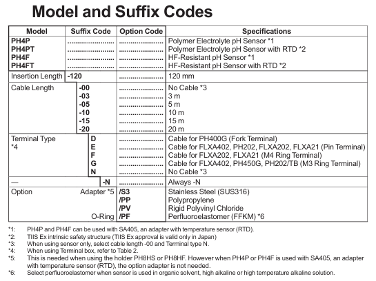
Installation and wiring process
1. Preparation before installation
(1) Unpacking and Inspection
Confirm that the appearance of the sensor is undamaged (glass body, cable without cracks), and the model and suffix code (such as PH4F-05-E/S3) are consistent with the order;
Check the integrity of attachments: storage cap (including protective liquid), O-ring (default fluororubber, optional/PF), adapter (such as/S3);
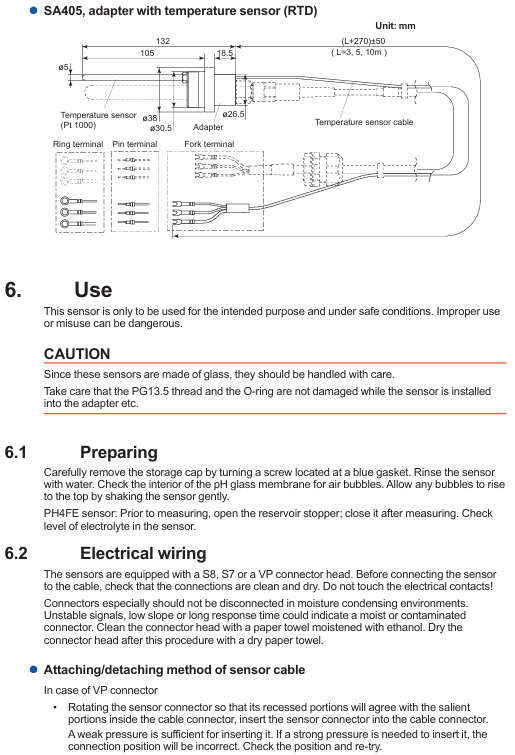
When removing the storage cap, use a screwdriver to unscrew the screw at the blue gasket to avoid damaging the glass electrode; Check the "gas layer length" of PH4C/OR4C (confirm that the internal pressure is normal).
(2) Installation site selection requirements
Avoid areas where bubbles gather (such as at the top of pipelines), dead zones, or locations with high flow rates (>2 m/s) to prevent response delays or electrode wear;
Anti HF models (PH4F/PH4FT) should be kept away from strong oxidizing media (such as concentrated nitric acid) to avoid accelerated glass corrosion;
The installation in hazardous areas must comply with the IEC 60079-14 standard, and as a "simple device", it should be matched with an isolated transmitter (such as FLXA202) with a grounding resistance of ≤ 1 Ω.
2. Core installation steps (taking the flow bracket PH8HF as an example)
(1) Adapter and O-ring assembly
Select adapter: Choose the material based on the corrosiveness of the medium (such as S3 stainless steel adapter for acidic medium), and insert the O-ring (default FPM or optional/PF) into the adapter groove;
Pre installed sensor: Thread the sensor through the bracket fixing nut, insert the adapter, and ensure that the glass electrode is completely in contact with the medium channel (without air residue);
Tighten and fix: Tighten the nut clockwise to the O-ring compression seal (to avoid damaging the glass due to over tightening). For medium pressure models (PH4C/OR4C), it is necessary to confirm that the process pressure is ≤ the internal pressure of the sensor.
(2) Cable and terminal connection
The sensor cable contains 4-5 core wires (with an additional 1 core for RTD models), which need to be connected to the transmitter (such as FLXA202) according to the terminal definition. The wiring method is consistent for different terminal types:
Cable core function corresponding terminal (FLXA202 as an example) Remarks
The pH/ORP indicator electrode (GE) transmits measurement signals to terminal 15, ensuring that the wiring is secure and avoiding interference;
The reference electrode (RE) terminal 13 forms a circuit with the indicator electrode and needs to be grounded separately;
The grounding electrode (SE) terminal 14 must eliminate the grounding potential difference and be reliably grounded (grounding resistance ≤ 1 Ω);
RTD (T1/T2, with RTD model) terminals 11/12 are only available for PH4PT/PH4FT/PH4CT and are used for temperature compensation;
VP connector operation: Rotate the sensor connector to align the groove with the cable connector protrusion, gently insert and tighten the nut (only tighten the plastic part to avoid glass damage);
Terminal box usage: WTB10 terminal box is required for long-distance installation (>10m), with a total cable length of ≤ 20m to avoid signal attenuation.
Operations and Calibration
1. Daily maintenance
(1) Electrolyte replenishment and replacement
PH4P/PH4F/OR4P (polymer/gel type): there is no need to supplement electrolyte, and the sensor is replaced as a whole after its service life expires (usually 1-2 years);
PH4C/OR4C (pressurized type): The initial internal pressure is 250 kPa, which drops to about 125 kPa after 1 year of use. If the process pressure exceeds the internal pressure and the medium infiltrates, causing the sensor to fail, it needs to be replaced in advance;
PH4FE (fermentation specific): Regularly open the electrolyte replenishment port and replenish 3M KCl-LR solution to the liquid level line to avoid dry burning.
(2) Electrode cleaning
Choose the cleaning method based on the type of medium contamination, only clean the sensor tip (to avoid damaging the cable/connector):
Inorganic dirt (scale, salt): Use a soft cloth dipped in 1-2% dilute hydrochloric acid to wipe, and then rinse with pure water;
Organic dirt (oil, biofilm): Soak in neutral detergent solution (30 minutes to 2 hours), or use protease solution (such as hydrochloric acid solution containing gastric protease) in fermentation scenarios;
ORP electrode oxidation: Use a soft cloth dipped in toothpaste (mild abrasive) to wipe the platinum wire/platinum ring to remove the oxide layer.
2. Calibration process
(1) PH sensor calibration (two-point calibration method)
Prepare buffer solution: Select two points that are close to the process pH (such as pH 4.01+6.87, or pH 6.87+9.18), with the same temperature as the process;
Clean the sensor: Rinse the sensor with pure water to absorb surface moisture (avoid dilution with buffer solution);
First point calibration: Immerse in the first buffer solution (such as pH 6.87), wait for the reading to stabilize, and then follow the transmitter (such as FLXA202) prompts to perform "zero point calibration";
Second point calibration: Rinse with pure water and immerse in a second buffer solution (such as pH 4.01), perform "slope calibration", and ensure that the slope is ≥ 96%;
Verification: After calibration, return the first buffer solution with an error of ≤ 0.02 pH. Otherwise, clean and calibrate again.
(2) ORP Sensor Calibration (Quinone Hydroquinone Standard Method)
Prepare standard solution: Dissolve 1g of quinone hydroquinone powder in 200mL of pH 7.00 buffer solution and stir until saturated;
Calibration operation: Immerse the ORP sensor in a standard solution, wait for the reading to stabilize, and then enter the theoretical value according to the transmitter prompt (ORP=88 mV, rH=23.6 at pH 7);
Error allowance: Calibration error ≤ ± 10 mV. If it exceeds the tolerance, the platinum electrode needs to be cleaned and recalibrated.
3. Storage and regeneration
Short term storage (<1 month): Put on a storage cap and inject 1.5-2mL of 3.3M KCl solution to avoid electrode drying;
Long term storage (>1 month): It is recommended to replace the storage solution every 3 months to prevent electrolyte deterioration;
Sensor regeneration: If the sensor is dry or the response slows down, the pH sensor can be soaked in 0.1M NaOH (10 minutes) → 0.1M HCl (10 minutes) → 3.3M KCl (15 minutes); Clean the platinum surface of ORP sensor with abrasive.
- YOKOGAWA
- Reliance
- ADVANCED
- SEW
- ProSoft
- WATLOW
- Kongsberg
- FANUC
- VSD
- DCS
- PLC
- man-machine
- Covid-19
- Energy and Gender
- Energy Access
- Renewable Integration
- Energy Subsidies
- Energy and Water
- Net zero emission
- Energy Security
- Critical Minerals
- A-B
- petroleum
- Mine scale
- Sewage treatment
- cement
- architecture
- Industrial information
- New energy
- Automobile market
- electricity
- Construction site
- HIMA
- ABB
- Rockwell
- Schneider Modicon
- Siemens
- xYCOM
- Yaskawa
- Woodward
- BOSCH Rexroth
- MOOG
- General Electric
- American NI
- Rolls-Royce
- CTI
- Honeywell
- EMERSON
- MAN
- GE
- TRICONEX
- Control Wave
- ALSTOM
- AMAT
- STUDER
- KONGSBERG
- MOTOROLA
- DANAHER MOTION
- Bentley
- Galil
- EATON
- MOLEX
- Triconex
- DEIF
- B&W
- ZYGO
- Aerotech
- DANFOSS
- KOLLMORGEN
- Beijer
- Endress+Hauser
- schneider
- Foxboro
- KB
- REXROTH
- YAMAHA
- Johnson
- Westinghouse
- WAGO
- TOSHIBA
- TEKTRONIX
- BENDER
- BMCM
- SMC
- HITACHI
- HIRSCHMANN
- XP POWER
- Baldor
- Meggitt
- SHINKAWA
- Other Brands
- UniOP
- KUKA
- IBA
- Beckhoff
- ADLINK
-
FANUC A06B-0169-B088 - AC Servo Motor Alpha M40 3000 3 KW
-
ALPHA WIRE 1299C-SLATE-1000 - Multi-Conductor Cable Wire
-
alpha / Wittenstein SK+180S-MF1-10-1M1-1K - Hypoid Gearbox i=10
-
ALPHA WIRE 1181/40C SL005 - Multi-Conductor Cable Wire
-
Generic / DSI Straight Anatomic Plastic Adapter Head + Screw Hex - Dental Implant Fixture
-
Alpha II-650 MV6500526A - Power Supply Unit
-
ALPHA WIRE 7036 WH001 - Hook-Up Wire
-
FANUC RDCGM00000004O / TP 050-MF1-7-061-000 - Gear Reducer / Alpha Gearbox
-
Alpha II-650 MV6500436A - TDK-Lambda Power Supply Unit
-
Alpha S-Alpha600 J60033 - 600W Switching Power Supply Unit
-
Alpha 1500W J00032 - Power Supply Unit
-
Alpha 600W H60638 - Switching Power Supply Unit
-
Alpha 650 MV6500314A - Power Supply Unit
-
Aloka UST-5413 - Linear Probe for Prosound Alpha 6
-
ALPHA WIRE TFT25015 NA002 - High Temperature Heat Shrink Tubing Wire Sleeving
-
JAVAD ALPHA2 / GrAnt-G3 - GPS Receiver
-
Alpha 400W H47318 - Switching Power Supply Unit
-
Alpha SG-ALPHA-202-001 / Q1001-010-001 - Circuit Board Module
-
Antlia Dual ERF H-Alpha & Cak/CaH - Density Astronomical Accessory
-
ALPHA WIRE 5100C SL033 - Multi-Conductor Cable Wire
-
ALPHA WIRE 5098C-SL033 - Multi-Conductor Cable Wire
-
Fanuc A06B-6290-H105 - Alpha Sv 80hv-B Module Servo Amplifier
-
FANUC A06B-6240-H105 - Aux Axis Alpha aiSV 80 Servo Amplifier
-
Endress+Hauser Alpha-Log RSA10-61B1S / 42974737/0130 - Data Logger Measurement Instrument
-
ALPHA WIRE 6363-SL002 - Multi-Conductor Cable Wire
-
Alpha SP100S-MF1-7-1K1-2S - Gear Reducer
-
Alpha SP 100G-MF1-4-0H1-2S-PGG - Planetary Gear Reducer
-
FANUC A06B-0143-B175 #0275 - Alpha 12/3000 AC Servo Motor
-
James Burn Alpha Doc P33 / GBC PDI - Automatic Punch DocuPunch
-
Titus HVAC 105383-01 - ALPHA BAC Controller and Actuator
-
Wittenstein Alpha SP 100S-MF2-20-0E0-2S - Planetary Gearbox i=20
-
Kashiyama Alpha-85-ZV / SP-8026G - Pump Controller
-
Christ Alpha 2-4 LDplus - Freeze Drier Part N/ 101542
-
Lambda / Alpha H40896 - 400W Power Supply Unit
-
Wittenstein Alpha LP-070S-MF1-3-1E1-38 - Planetary Gearbox
-
Matrox / EXO-2480 133-D06-3 / 398-17962-1 - Alpha Numeric PCB Board
-
Fanuc A06B-6096-H204 - Dual Axis Alpha Servo Amplifier Module
-
Alpha Wire 5002C-SL001 - Multi-Conductor Cable 2 Conductors 22AWG 300VAC
-
Alpha 600W H60638 - Switching Power Supply Unit
-
Alpha Scientific Spin Precession Dual Electro Magnet Beam Line Chamber - Electro Magnet Beam Line Chamber
-
ALPHA WIRE 6017C SL005 - Multi-Conductor Cable Wire
-
ALPHA WIRE 65804 SL002 - Multi-Conductor Cable Wire
-
Fanuc A06B-0152-B010 - AC Servo Motor Alpha A30/2000 with Brake
-
ALPHA WIRE 5856-VI001 - Hook-Up Wire
-
ALPHA WIRE M13142-SL001 - Multi-Conductor Cable Wire
-
Alpha & Omega AOZ1017 - 8-Pin SOIC SMD Buck Switching Regulator IC
-
Alpha 600W H67027 CA600 - 600W Switching Power Supply Unit
-
ALPHA WIRE 2845/7-RD001 - Hook-Up Wire
-
Wittenstein Alpha VH+063S-MF1-10-6H1-1K-0C2 - Worm Gear Reducer i=10
-
ALPHA WIRE 2414C SL022 - Multi-Conductor Cable Wire
-
ALPHA WIRE 5672-SL005 - Multi-Conductor Cable Wire
-
BECKHOFF / Alpha AM8021-0B10-0000 + CP 040-MO1-10 - Servo Motor with Planetary Gearbox
-
ALPHA Systems Lab Inc MBA-WV1-F / PCB-WV1-F - PCB Board
-
FANUC A06B-0826-B201 - Alpha P12 AC Spindle Motor
-
WF & HC / Alpha-E 10045 - Tiller Bar Flat Flange Inlet 3150LB 3X 2.5 Inch
-
Seiler Alpha Air 3 - Dental Microscope
-
Alpha 400W H47223 - Switching Power Supply Unit
-
Wittenstein Alpha SP 180S-MC1-5-1M0-2K - Planetary Gearbox
-
FANUC A06B-6117-H211 - Servo Amplifier Module Alpha iSV 160/160 Amp
-
Alpha S-Alpha600 J60033 - 600W Switching Power Supply Unit
-
Adaptive Alpha Eclipse StreetSmart Model 17X - Master Slave LED Sign 44 x 44 Inch
-
ALPHA WIRE 391697-WH005 / 391697WH005 - Hook-Up Wire
-
Generic 22W Laser Engraver Cutter - Smart Air Pump APP Control CNC Dual-core CPU DIY Tools
-
FANUC A06B-6102-H226 / A06B6102H226 - Spindle Amplifier Module
-
FANUC A06B-6090-H006 / A06B6090H006 - Servo Power Supply Module
-
Alpha Wire Apr-19 - High Low Temperature Cable 75 FT
-
Wittenstein Alpha HG+ 075S-MF2-28-6E1-1S10 - Hypoid Gearbox Reducer i=28
-
Alpha J00032 - 1500W Power Supply Unit
-
Alpha H47038 - 400W Power Supply Unit
-
FANUC A06B-6096-H204 - Dual Axis Alpha Servo Amplifier Module
-
Wittenstein Alpha LPB090-MO1-10-111-00 - Alpha Planetary Gearbox
-
ALPHA WIRE 2842/19-YL001 - Hook-Up Wire
-
WITTENSTEIN ALPHA HG+060S-MF1-56C1-1K00 - Planetary Gearbox
-
Basler A102K Alpha VIS - Black and White CCD Industrial Camera
-
Alpha H40935 - 400W Power Supply Unit
-
FANUC A06B-6114-H207 - 2-Axis Servo Amplifier Module SVM20/40i Alpha i Series
-
TDK-Lambda / Alpha H47318 - 400W Switching Power Supply Unit
-
HITACHI Aloka Prosound Alpha 7 Premier - Diagnostic Ultrasound System
-
Alpha SP100S-MF1-4-1E1-2S - Precision Gear Reducer
-
FANUC A20B-2001-0950 - Control Circuit Board PCB
-
ALPHA WIRE 2855/1-GR001 - Hook-Up Wire
-
FANUC A06B-6096-H204 - Dual Axis Alpha Servo Amplifier Module
-
Wittenstein Alpha LPB090-MO1-10-111-00 - Alpha Planetary Gearbox
-
ALPHA WIRE 2842/19-YL001 - Hook-Up Wire
-
Basler A102K Alpha VIS - Black and White CCD Industrial Camera
-
Wittenstein Alpha LP 090-M01-7-111-000 / Schneider - Gear Box i:7 Schneider Electric Servo Motor
-
LAMBDA ALPHA 600W H60554 - Switching Power Supply Unit
-
Fanuc A06B-0238-B100 / A860-2000-T301 - AC Servo Motor with Encoder
-
FANUC A06B-6290-H322 - ALPHA iSV 10/10/10HV-B 3-Axis Servo Drive
-
Polymotor Italiana 9919 121 90332 / Alpha SP75-M1-3 - D.C. Permanent Magnet Motor with Gearbox
-
MJ Research PTC-200 - PCR DNA Engine Thermal Cycler with Dual 48-Well Alpha Block
-
ALPHA WIRE 5002C-SL002 - Multi-Conductor Cable Wire
-
Fluke / Victoreen ASM 990 / 489-110D - Biomedical Radiation Detector Probe with Pelican Case
-
ALPHA WIRE 5855-BK001 - Hook-Up Wire 22AWG Silver Plated Copper
-
Tetra / Alpha 600W H60552 - Switching Power Supply Unit
-
Bruker Alpha FTIR Spectrometer / Alpha-P ATR - Infrared Spectrometer FTIR Instrument
-
Simagic AlphaM-FX-C 290mm FX-C - Formula Steering Wheel with Alpha Mini Wheel Base
-
Alpha Wire 5152C 20/2C - XtraGuard High Performance Instrumentation/Control Cable
-
ALPHA WIRE 1219/40C SL005 - Multi-Conductor Cable Wire
-
ALPHA WIRE 3131441 TN005 - Multi-Conductor Cable Wire
-
ALPHA WIRE 2172-SV005 - Multi-Conductor Cable Wire
-
FANUC A20B-2100-0742 - ALPHA ia Servo Control Board
-
Olympus Endo Alpha Cart TI-A1 - Medical Equipment Cart with Accessories
-
ALPHA WIRE 74010-BK002 - Multi-Conductor Cable Wire
-
Fanuc A06B-6110-H026#N - ALPHA i Power Supply Module PSM-26i
-
Alpha Laval SX2/013 - Rotary Lobe Pump
-
Alpha II-450P MV4500007B - Switching Power Supply Unit
-
TDK-Lambda / Alpha 400W - Switching Power Supply Unit
-
ALPHA ALPHA6000E-3015GB/3018PB - Frequency Inverter Drive Power Converter
-
ALPHA WIRE 391245-WH005 - Hook-Up Wire
-
Alpha H60562 CA600 - 600W Switching Power Supply Unit
-
Fanuc A06B-0147-B675 - Alpha 22/2000 3.8kW 2000rpm AC Servo Motor
-
ALPHA WIRE 9821 - Twinaxial Cable 1PR 25AWG Poly Insulation
-
Fanuc / Alpha A16B-2203-0820 - ALPHA i Spindle Wiring PCB
-
FANUC A20B-2100-0742 - ALPHA ia Servo Control Board
-
Fanuc A06B-6096-H104 - Alpha Servo Module
-
Fuji Electric RYT202D5-VV2 / Faldic Alpha5 - Servo Amplifier
-
ALPHA WIRE 2817/6 20 AWG - PTFE High Temperature Cable
-
Aloka Prosound Alpha 10 / EU-6031C / JB-274D - High Voltage Power Supply for Ultrasound
-
Wittenstein Alpha SP 140S-MF1-5-01F-2S - Planetary Gearbox
-
FANUC A06B-6124-H205 - Alpha iSV Servo Amplifier Module
-
TDK-Lambda / Alpha MV6500314A - 650W Power Supply Unit
-
TDK-Lambda / Alpha H47318 - 400W Switching Power Supply Unit
-
Alpha H47318 - 400W Switching Power Supply Unit
-
CNC Bearing / Alpha AR090-S1-300-20-N - Robotics Bearing Component
-
Alpha CA400 5A,3.3Q,5B,12/12E / DXH47037 - 400W Power Supply Unit
-
FANUC A20B-2100-0742 - ALPHA ia Servo Control Board
-
Fanuc / Amada A04B-0810-C403 / LC1212 alpha II - Pressure Regulator

K-JIANG

Add: Jimei North Road, Jimei District, Xiamen, Fujian, China
Tell:+86-15305925923