
K-WANG


YOKOGAWA SC210G Conductivity Detector
Corresponding manual number for supporting equipment type
FLXA202, FLXA21 2-wire liquid analyzer IM 12A01A02-01E
FLXA402 4-wire converter IM 12A01F01-02EN, IM 12A01F03-01EN, etc
FLXA402T turbidity and chlorine liquid analyzer IM 12A01G01-02EN, IM 12A01G03-01EN, etc
SC450G 4-wire conductivity converter IM 12D08N05-01E
YOKOGAWA SC210G Conductivity Detector
Equipment foundation and system composition
1. Core positioning and adaptation system
SC210G is a conductivity detection unit that needs to be used in conjunction with a specific analyzer/converter to form a complete detection system. The compatible equipment and corresponding manual information are as follows:
Corresponding manual number for supporting equipment type
FLXA202, FLXA21 2-wire liquid analyzer IM 12A01A02-01E
FLXA402 4-wire converter IM 12A01F01-02EN, IM 12A01F03-01EN, etc
FLXA402T turbidity and chlorine liquid analyzer IM 12A01G01-02EN, IM 12A01G03-01EN, etc
SC450G 4-wire conductivity converter IM 12D08N05-01E
2. Equipment core classification and parameters
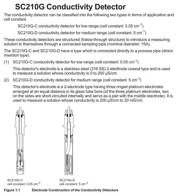
SC210G can be divided into two categories based on measurement range, with the core difference in electrode structure and conductivity range, suitable for different solution detection scenarios:
Model Measurement Type Electrode Structure Battery Constant Measurement Range Applicable Scenarios
SC210G-C low range 316 stainless steel 2-electrode coaxial type 0.05 cm ⁻¹ 0-200 µ S/cm low conductivity solution (such as ultrapure water)
SC210G-D medium range glass tube with equidistant 3-ring platinum electrodes (short circuited on both sides and forming a counter electrode in the middle) 5 cm ⁻¹ 200 µ S/cm-20 mS/cm medium high conductivity solution
3. General technical specifications
Temperature and pressure: Normal temperature 0-105 ℃ (polypropylene material bracket is limited to 0-100 ℃); Conventional pressure 0-1 MPa (polypropylene material support limit 0-500 kPa)
Contact fluid material: SC210G-C (sensor: 316 stainless steel, fluororubber O-ring, polytetrafluoroethylene; Main body: 316 stainless steel, polypropylene); SC210G-D (sensor: platinum, glass, fluororubber O-ring; Subject is the same as Type C)
Temperature compensation: Built in Pt1000 temperature sensor, used to calibrate the effect of temperature on conductivity
Protection level: JIS C0920 waterproof (equivalent to NEMA 4), suitable for humid environments in industrial sites
Safety regulations and usage restrictions
1. Core security principles
Prohibited unauthorized operation: Only use according to the instructions in the manual, unauthorized modification of the device will result in loss of protective function; Repairs require Yokogawa certified spare parts, unauthorized modifications are prohibited
Static electricity and explosion prevention: Non metallic components may carry static electricity, and it is necessary to avoid static electricity generation operations such as wiping with dry cloth; The junction box shell is made of aluminum, which can avoid impact, friction, and sparks; Must comply with explosion-proof standards such as IEC 60079-11 (TIIS certified models cannot be connected)
Temperature limit: The maximum process temperature needs to be determined based on the supporting analyzer (FLXA202/FLXA21/SC202S) and temperature level (T1-T6). For example, under T5 level, FLXA202/FLXA21 with SC210G-C has a maximum process temperature of 54 ℃ at an ambient temperature of 40 ℃, and with SC210G-D it is 95 ℃ (note that the upper limit of T5 level is 100 ℃)
2. Manual usage guidelines
It needs to be handed over to the end user and properly stored, and unauthorized copying/dissemination is prohibited; Yokogawa reserves the right to improve manuals and equipment without prior notice
The manual only describes the device functions and does not guarantee adaptation to specific user scenarios; The equipment is provided as is, and Yokogawa is not responsible for unforeseeable direct/indirect losses
Installation and Wiring Guide
1. Installation type and preparation
SC210G is divided into direct insertion type (installed in process pipelines) and flow type (sample introduced through sampling tubes). Before installation, it is necessary to:
Site selection requirements: easy maintenance, no bubbles in the solution (to avoid measurement deviation), stable liquid level, and away from high temperature (>50 ℃) pipelines
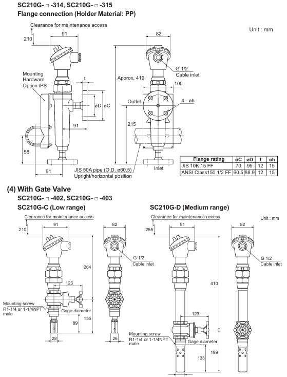
Preprocessing: For direct insertion type, corresponding thread holes (such as R1-1/2, 1-1/2 NPT) or flange holes (JIS 10K 50 RF, etc.) need to be reserved; The circulating polypropylene bracket needs to be equipped with a 50A pipe (outer diameter 60.5mm) and fixed with a bracket to prevent rupture
2. Installation steps
Direct insertion type: Threaded type requires sealing tape to be wrapped around the thread and screwed in; The flange type requires adding gaskets between the flange faces and evenly tightening 4 bolts
Flow type: fixed to the designated installation pipeline, adjustable solution inlet and outlet direction (stainless steel bracket can be adjusted horizontally, polypropylene bracket can be adjusted through the bracket direction)
Direction adjustment: Loosen the union nut of the junction box to rotate it for easy wiring (rotating without loosening the nut will damage the internal wiring)
3. Requirements for piping and wiring
Piping: Hard PVC pipes (JIS K9741, A16) for polypropylene supports, etc; 304/316 stainless steel pipes (JIS G3459, A15) are used for stainless steel brackets; Suggested flow rate<20 L/min (to prevent electrode wear caused by slurry solution), an overflow tank should be installed to remove bubbles, and a shut-off valve should be installed at the maintenance site to prevent leakage
Wiring: The cable length is provided according to the order (3/5/10/15/20m), and the terminals are divided into M4 ring type (compatible with FLXA202/FLXA21), M3 ring type (compatible with FLXA402/FLXA402T/SC450G), and pin type (compatible with multiple devices); The cable should avoid contact with high-temperature components, and the joint locking nut should be tightened for waterproofing after connection. The insulation resistance between the core wires should be ≥ 2 M Ω
Operation and maintenance process
1. Preparation before operation and steady-state operation
Inspection items: correctness of wiring, compatibility of piping materials, solution level (flow type needs to go to the outlet), no leakage; After startup, it is necessary to confirm that there is no bubble interference and no sudden temperature changes (to avoid affecting measurement accuracy)
Steady state maintenance: Conventional solutions (free of pollutants) can be maintained for 1 year without maintenance; Regular calibration with standard solution is required to ensure accuracy; If the analyzer outputs a FAIL signal, refer to the analyzer manual for troubleshooting
2. Core maintenance operations
(1) Electrode cleaning
Cleaning cycle: Low range (0.05 cm ⁻¹) electrodes require almost no cleaning due to minimal impurities in the solution; Medium range (5 cm ⁻¹) electrodes should be cleaned as needed (if the analyzer indicates abnormal electrode polarization)
Cleaning method: Type C (clean the inner and outer electrodes, only the inside of the hole needs to be cleaned externally); D-type (glass material requires a protective tube, gently wipe the platinum electrode on the inner wall of the glass tube with a thin rod wrapped in degreasing cotton)
(2) O-ring replacement
Replacement timing: O-ring damage can cause leakage, and regular inspections are required in high-temperature solution scenarios; Conventional O-ring (fluororubber, model K9050AT/K9050MR), with gate valve model requiring replacement with dedicated O-ring (K9050MS)
Replacement steps: For non gate valve types, simply loosen the union nut and remove the electrode to replace it; The gate valve type needs to first remove the external electrode and locking nut, remove the stop screw and replace the O-ring (recommended to replace in pairs), and calibrate the battery constant after reinstallation
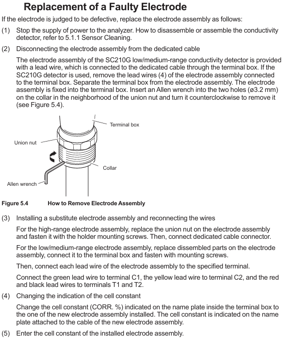
(3) Electrode component replacement
Replacement condition: When the electrode is judged to be faulty (if there is still a large deviation after calibration)
Step: Power off → Remove the connection between the junction box and the electrode (use an Allen wrench to unscrew the electrode assembly) → Install a new component and wire it according to the color (green → C1, yellow → C2, red/black → T1/T2) → Update the battery constant label in the junction box → Enter the new battery constant in the analyzer
- YOKOGAWA
- Reliance
- ADVANCED
- SEW
- ProSoft
- WATLOW
- Kongsberg
- FANUC
- VSD
- DCS
- PLC
- man-machine
- Covid-19
- Energy and Gender
- Energy Access
- Renewable Integration
- Energy Subsidies
- Energy and Water
- Net zero emission
- Energy Security
- Critical Minerals
- A-B
- petroleum
- Mine scale
- Sewage treatment
- cement
- architecture
- Industrial information
- New energy
- Automobile market
- electricity
- Construction site
- HIMA
- ABB
- Rockwell
- Schneider Modicon
- Siemens
- xYCOM
- Yaskawa
- Woodward
- BOSCH Rexroth
- MOOG
- General Electric
- American NI
- Rolls-Royce
- CTI
- Honeywell
- EMERSON
- MAN
- GE
- TRICONEX
- Control Wave
- ALSTOM
- AMAT
- STUDER
- KONGSBERG
- MOTOROLA
- DANAHER MOTION
- Bentley
- Galil
- EATON
- MOLEX
- Triconex
- DEIF
- B&W
- ZYGO
- Aerotech
- DANFOSS
- KOLLMORGEN
- Beijer
- Endress+Hauser
- schneider
- Foxboro
- KB
- REXROTH
- YAMAHA
- Johnson
- Westinghouse
- WAGO
- TOSHIBA
- TEKTRONIX
- BENDER
- BMCM
- SMC
- HITACHI
- HIRSCHMANN
- XP POWER
- Baldor
- Meggitt
- SHINKAWA
- Other Brands
- UniOP
- KUKA
- IBA
- Beckhoff
-
LTI SC52.0040.0012.0000.0 - Servo Drive
-
Lti SC52.0040.0012.0000.0 - Servo Drive
-
Milton Industries LTI Tool By Milton LT1240 - 1/2" Drive Lugnut Remover
-
LTi Drives SO84.200.P030.0000.0-W - Servo Spindle Drive
-
LTI DRIVES LSP08-035-320-30-B0R1PY170 - Servo Motor
-
LTI DRIVES SE84.200.SC00.0001.0-W - Servo Drive
-
Lust CDE34.005.W2.2 - Lti Drives Controller
-
LTi SO84.012.0030.0011.2 - ServoOne Servo Drive
-
LTi Drives SO CM-P.0010.11.00.0 - Servo Drive Controller
-
LTi CDE34.017.W3.0 - Servo Drive
-
LTI Drives CDB32.004, C2.0,SH - Positioning Controller
-
LUST CM-CAN1 - LTi DRIVES Communication Module
-
LTi SO84.012.1030.0000.2 - Servo Drive
-
LTI MOOG CDE54.044 - PITCHMASTER FREQUENCY CONVERTER 181-01019
-
MOOG LTI 181-01019 CDE54.044 - PITCHMASTER FREQUENCY CONVERTER
-
Lust LTi Drives CDE34.010,D2.0 - Servo Drive Controller
-
LTI SO84.032.0003.0101.2 - Servo Drive
-
Seagate 9CC132-302 Harris LTI-CS IRT-34-0021-01 - Hard Drive 160GB
-
LTI SO84.032.0003.0001.2 - Servo Drive
-
LTI SO24.007.0070.0000.1 - SERVO CONTROLLER
-
LTi drive CDA32.003.C3.0.H05-01.PC1 - Servo Drive
-
LTI SO84.016.0030.0000.2 - SERVO CONTROLLER
-
LUST LTI CD A34.008,W1.4, BR - SERVO DRIVE
-
MOOG LTI 181-01019 CDE54.044 - PITCHMASTER FREQUENCY CONVERTER
-
LTI MOOG 181-01019 - PITCH Master Servo Drive CDE54.044
-
LTI SERVO ONE SO84.045.0030.0001.2-W - Drive
-
LUST LTi SO84.032.0040.0000.2 - SERVO ONE DRIVE
-
LTi Drives LSH-074-2-30-3 20/T1,G6.1M - SERVO MOTOR
-
LTI SO84.016.0000.0101.2 - servo drive
-
LTI SA54.0550.0033.0000.0 - Servo Drive
-
LTI SA54.0550.0033.0000.0 - Servo Drive
-
LTI LT 4850 - 3/8" Drive 3-Pc Twist Socket Transmission Drain Plug Removal System
-
LTI Tools LT4400-30 Lock Technology - 3/4" Twist Socket 1/2" Drive Lugnut Remover
-
LTI Tools LT-1400C - 1/2 Drive Wheel Torque Extension Tool
-
LTI Tools LT1250 - 1/2" Drive Dual Sided Socket Lug Nut Remover Tool
-
LTI SO84.032.0003.0101.2 - Servo Drive
-
LTI MOOG 181-01019 - PITCH Master Servo Drive CDE54.044
-
MOOG LTI 181-01019 CDE54.044 - PITCHMASTER FREQUENCY CONVERTER
-
MOOG LTI 181-01019 CDE54.044 - PITCHMASTER FREQUENCY CONVERTER
-
MOOG LTI 181-01019 CDE54.044 - PITCHMASTER FREQUENCY CONVERTER
-
LTI SA54.0550.0033.0000.0 - Servo Drive
-
LTI Tools LT-4800 - 7 Piece Twist Socket 3/8" Drive Oil Drain Plug Removal Set
-
LTI SA54.0550.0033.0000.0 - Servo Drive
-
LTI Drive SO24.007.00300000.0 - Servo Drive
-
LTI TOOLS LTI 1400-I - Drive Wheel Torque Extension
-
LTI Tools LT4400-3 - 3/4" 19mm Twist Socket 1/2" Drive Lugnut
-
LTI TOOLS LTI 1400-BB - Drive Wheel Torque Extension
-
LTI SO84.032.0003.0101.2 - Servo Drive
-
LTI Tools LT-4512 - 3/8" Drive 12mm Twist Socket
-
LTI MOTION Luster SO84.032.0003.0001.2 - Servo Drive
-
LTI Tool By Milton LT1600P - 1" Drive Torx Stick
-
LTI Lust VF1424L,HF,OP2,S56 - Variable Frequency Drive
-
LUST CDA32.004,C1.4,H08,B0 - SERVO DFRIVE CM-CAN1 Module
-
LTI SO84.045.0002.0001.2-W - Drive
-
LTI Lust VF1404M,C9,PT1,BR1 - Inverter Type VF1404M
-
LTI SA54.0550.0033.0000.0 - Servo Drive
-
LTI Tools LT-1400C - 1/2" Drive Wheel Torque Extension
-
Lust LTI DRiVES CDA32.006, C3.0, H09 - Variateur De Fr茅quence Frequency Inverter
-
LTI MOOG CDE54.044 - PITCH master SERVO DRIVE
-
LTI MOOG CDE54.044 - PITCH master SERVO DRIVE
-
LTI SO84.143.0020.0101.2-W - servo drive
-
LTI MOTION SC34.0200.0011.0000.0 - Servo drives
-
LTI SO84.032.0003.0001.2 - Servo Drive
-
LTI DRIVES GmbH MS100 - Assembly Set Mounting Kit
-
LTI SO84.032.0003.0001.2 - Servo Drive
-
LTI SO84.032.0003.0001.2 - Servo Drive
-
LTI MOTION SO84.032.0003.0101.2 - servo drive
-
LTI SO84.032.0003.0101.2 - Servo Drive
-
LTI MOOG CDE54.044 - PITCH master SERVO DRIVE
-
LTI MOTION CDE32.004.C2.4 - Servo drives
-
LTI CDD34.032锛學x.x锛孊R锛孭C1 - Servo Drive
-
Lust LTI DRiVES CDA32.006, C3.0, H09 - Inversor De Frecuencia Frequency Inverter
-
Lust SO84.008.0030.1000.0 - Servo One LTi Drive
-
LTI MOTION SO84.032.0003.0101.2 - Servo drives
-
LUST LTi CDA32.004,C1.4 - SERVO DRIVE
-
LTI MOOG CDE54.044 - PITCH Master SERVO DRIVE
-
LTI KEBA CDB32.004 C2.7, SH - PN: 08673530 Frequency Inverter
-
LTI Tools LT-1400C - 1/2" Drive Wheel Torque Extension
-
LTI LT1400-E - 1/2" Drive Wheel Torque Extension
-
LTI MOOG 181-01019 - PITCH master SERVO DRIVE CDE54.044
-
LTI LSN-097-0510-30-560/T1 - Actuator Motor
-
LTI Tools LT 4800 - 7 Piece 3/8" Drive Twist Socket Oil Drain Plug Removal System
-
LTI DRIVES GmbH MS100 - MONTAGESET Assembly Set Mounting Kit
-
Lti SC52.0040.0012.0000.0 - Servo Drive
-
LTI DRIVES GmbH MS100 - Juego De Montaje Assembly Set Mounting Kit
-
LTi DSM4-14.2-21R83-200 - Drives servomoteur Servo Motor
-
MOOG CDE 54.044.GDA - Pitch Master Industrielle Turbine Lti Drive
-
LTI SO24.004.0030.1000.0 - Servo Drive Controller
-
Lti MOOG CDE54.044 - Pitch Master Servo Drive
-
Lust LTI DRiVES CDA32.006, C3.0, H09 - Inverter
-
LTI MOTION GMBH CDB34.006,W3.0,PC1,H39 - Frequency inverter
-
LTI SO84.032.0003.0001.2 - Servo Drive
-
MOOG CDE 54.044.D - Pitch Master Industrielle Turbine Lti Drive
-
LTI TOOLS LT-1460 - 1/2" DRIVE WHEEL TORQUE EXTENSION KIT 5 PIECE SET
-
Lust Cdb32.003, C2.4 - Lti Drives Servoregulador Frecuencia Servo Controller Inverter
-
Lust LTI DRIVES CDA32.006, C3.0, H09 - Frequency Inverter
-
Lust Lti SO82.004.0030.0000.2 - Servo Drive
-
LTI MOTION SC34.0200.0011.0000.0-SL - Servo drives
-
LTI MOTION SA54.0075.0033.0000.0 - Servo drives
-
LTI MOTION SC32.0075.1011.0000.0 - Servo drives
-
LTI Servo-One Junior SO22.006.0080.1000.0 - Servo Controller Servoregler
-
LUST CDA32.004, C1.4, H08, B0 - Servo Drive & LTI CM-CAN1 Module
-
LTI DRIVES LSP08-035-320-30-B0R1PY170 - Servo Motor
-
LUST LTI CDA32.004,C1.4.H08.B0 - SERVO CONTROLLER DRIVES
-
LUST LTi DRiVES CDS44.072LC1.2 - Servo Drive
-
Lti Servo-One Junior SO22.006.0082.1000.0 - Servo Controller Servoregler
-
LUST CDA32.008,C2.0,HF - Lti DRIVES Spindle Drive Inverter
-
LTI SO22.003.0082.0000.0 - Servo Drives One junior Servo Controller Servoregler
-
Lust Lti Drives CM-CAN1 - Communication Module
-
LUST Lti Drives Vf1202s, G8, I6 - Frequency Inverter Drive
-
LTI DRIVES BR-090.03.540.UR.H38 - Bremswiderstand Brake Resistor
-
LTi DRIVES PM-E40.2DRA054P - Wind Turbine Pitch Control Inverter
-
LTi Drives GmbH br-110.01.540-UR - Brake Resistor
-
LTI Drives LSN-097-0960-30-0560/T1,S4,B - Servo Motor
-
LUST CDA34.006.C2.0 - LTI Drives Servoregler
-
LUST LTI DRIVES SERVO ONE JUNIOR SO24.002.0020.0000.1 - Servo Drive Controller
-
LTI MOTION SO84.032.0003.0001.2 - Servo drives
-
LTI DDTD750V2-120 - IBOP ACTUATOR CYLINDER FOR TOP DRIVE
-
LTI CDE32.004, C2.4 - SERVO DRIVE
-
LUST LTI DRIVES CDD34.017 W3.4PC1 - Servo Drive Controller
-
LTI CDA3208,C3,0,HF - AC SERVO DRIVE
-
LUST LTI DRIVES LSH-074-3-30-560/T1,G6.1S - SERVO MOTOR
-
LUST Lti CDB32.004.C2.4.SH - AC Servo Drive
-
LTi CDA32.006, C3.0, H09 - Servo Drive
-
LTI SO22.003.0010.0000.0 - Servo Drive Servo one junior Servoregler Controller
-
LTi Drives DSM4-14.2-21R83-200 - Servo Motor
-
LUST Lti Drives Lsh-097-1-30-560/T1, 1R - Servomotor
-
LTI 1237 - 7 Piece 1/2" Drive Flip Socket Set

K-JIANG

Add: Jimei North Road, Jimei District, Xiamen, Fujian, China
Tell:+86-15305925923