
K-WANG


Watlow PM PLUS ™ PID/Integrated Limit Controller
Watlow PM PLUS ™ PID/Integrated Limit Controller
Product Core Overview
Watlow PM PLUS ™ It is an enhanced PID/integrated limit controller that optimizes user experience and functional scalability while being compatible with the previous generation EZ-ZONE PM controller. The product is positioned as an industrial grade temperature and process control, supporting single/dual PID control loops and integrating functions such as limit control, timing, and curve programming. It is widely used in semiconductor manufacturing, chemical reactions, equipment heating, and other scenarios. Its core advantages include Bluetooth wireless configuration, intuitive touch operation, support for multiple communication protocols, and comprehensive security authentication, which can adapt to the precise control needs in complex industrial environments.
Core features:
Compatibility and Upgradeability: Fully compatible with the wiring and parameter settings of EZ-ZONE PM, can be replaced without hardware modification, and upgraded with smooth touch keyboard, multilingual display (English/German/Spanish) and other operations.
Control capability: Supports PID (including P/PI/PD mode), switch control, curve programming (4 curves, a total of 40 steps), equipped with TRU-TUNE+adaptive algorithm and automatic tuning function to improve dynamic control accuracy.
Communication and wireless functions: Supports Bluetooth (via EZ-LINK mobile application), Modbus RTU/TCP, EtherNet/IP, DeviceNet and other protocols, allowing remote configuration of parameters and monitoring, reducing on-site wiring dependence.
Safety and Certification: Certified by UL, CSA, CE, RoHS, FM, etc., some models support Class 1, Zone 2 hazardous environments, integrate limit control and multiple alarms to ensure equipment and personnel safety.
Product model and core configuration
(1) Model classification and structure
The product is divided into three series based on installation size and function. The core model parameters are defined by a 14 digit configuration code, and the key dimensions are as follows:
Classification, specific specifications, applicable scenarios
Installation size: 1/16 DIN (PM6), 1/8 DIN vertical (PM8), 1/8 DIN horizontal (PM9). Different panel space requirements, 1/16 DIN is suitable for compact scenarios, and 1/8 DIN is suitable for multi parameter display requirements
Core function - PID basic type (C/R/T/J/N): including universal input, curve programming (some models), and timing function
-Integrated limit type (L/M): Additional support for sensor backup, over limit protection, output 4 fixed limit control - Basic type: Single heating/cooling control
-Integrated type: Scenarios that require dual safety protection (such as high-temperature furnaces and hazardous material heating)
The power supply and I/O power supply can be selected from 100-240V AC or 20-28V AC/12-40V DC. The digital I/O supports 2-point or 6-point expansion to adapt to the global power grid. Multiple I/O point models can be connected to external trigger signals (such as emergency stop and start switches)
Output types support switch DC, mechanical relay (5A), SSR (0.5A), NO-ARC relay (15A), universal process output (0-10V/4-20mA) - NO-ARC relay: high-power resistive load (such as large heaters)
-Universal process output: signal retransmission to recorder or PLC
(2) Core hardware specifications
Category detailed parameters
Input Characteristics - Universal Input: Thermocouple (J/K/T/E, etc.), RTD (100 Ω/1k Ω), Process Signal (0-20mA/0-10V)
-Input accuracy: ± 0.1% range (typical value), temperature stability ± 100ppm/° C
-Sensor backup: supports dual sensor switching, automatically switches to backup sensor in case of failure
Output Capacity - Maximum Output: 15A NO-ARC Relay (AC Load Only)
-Process output: 0-10V (minimum 1k Ω load) or 4-20mA (maximum 800 Ω load), accuracy ± 20 μ A/± 10mV
Environmental adaptability - Operating temperature: 0-65 ° C (non condensing)
-Protection level: Front panel IP67/IP4X (indoor)
-Anti interference: Compliant with IEC 61000-4 series standards, anti-static and radio frequency interference resistant
Installation and wiring specifications
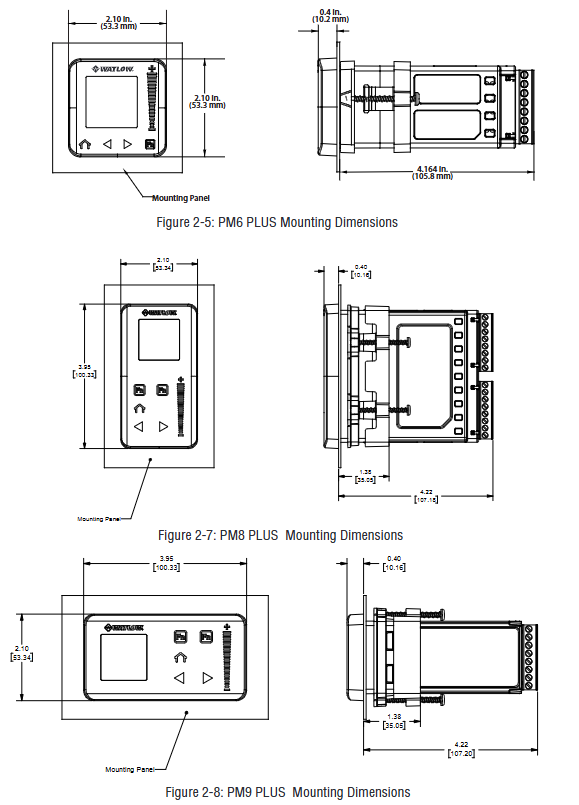
(1) Installation requirements
Panel opening and fixing
Size standards: 1/16 DIN (PM6) opening 45 × 45mm, 1/8 DIN (PM8/9) opening 45 × 92mm (vertical)/92 × 45mm (horizontal).
Installation steps: Remove the terminal and fixing ring → Insert the controller from the front of the panel → Align the fixing ring and tighten the screws (torque 3-4 in lbs) → Reinstall the terminal.
Environmental restrictions: Avoid corrosive gases and high vibration environments, install vertically to ensure heat dissipation, and reserve a spacing of ≥ 30mm for parallel installation of multiple units.
Power supply and wiring safety
Power adaptation: High power models (1/2) are connected to 100-240V AC, while low-power models (3/4) are connected to 20-28V AC/12-40V DC, and must match the power type indicated on the equipment label.
Wiring specifications: Wire specifications are 12-30 AWG, terminal torque is 5.0 in lb, unused terminals need to be empty, analog input and power/digital signals need to be isolated and wired to avoid grounding loops.
Attention to hazardous environments: Class 1, Zone 2 models (with "12" at the end of the configuration code) require the use of explosion-proof switches. It is prohibited to plug or unplug wiring when powered on, and replacement parts must comply with hazardous environment certification.
(2) Key wiring example
Sensor wiring
Thermocouple: Connect the negative electrode (usually red) to the S1/S2 terminal, and the extension wire should be consistent with the thermocouple material (such as K-type extension wire for K-type).
RTD: 2/3 wire system, 3-wire system needs to ensure that the resistance of the three leads is consistent (≤ 20 Ω), S1 is connected to a white lead to compensate for the lead resistance.
Process signal: 4-20mA signal connected to+R1/- S1 terminal, 0-10V signal connected to+T1/- S1 terminal, requiring separate shielded wiring.
Output and communication wiring
NO-ARC relay: only connected to AC loads (85-264V AC), load current ≤ 15A, prohibited from series use, cycle time ≥ 5 seconds.
Communication wiring: RS-485 uses twisted pair cables (T+/R+connected to B, T -/R - connected to A), and a 120 Ω terminal resistor needs to be added at the end of the bus. The distance between the communication line and the power line should be ≥ 305mm.
Digital I/O: 2-point I/O model (configuration code 2/4) supports dry contact or 3-36V DC input, 6-point I/O model (configuration code C/D/M/N) expandable switch output, with a maximum load of 1.5A per channel.
Operating interface and core functions
(1) User interface
Touch buttons and display
Key functions: Home button (return to home page), left and right buttons (menu navigation), increase and decrease buttons (parameter adjustment), custom function buttons (F1/F2, can set start/stop curves, reset alarms, etc.).
Display mode: default display of process values (such as temperature), set values, and regions, supporting 4 themes (such as white background, high contrast blue background), customizable display parameters (such as output power, remaining time).
Message prompt: Automatically switch display in case of alarm/error, such as "Limit High" or "Input Error". The lock alarm can be cleared by pressing the home button.
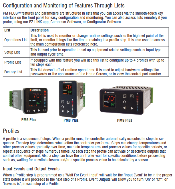
Menu Structure
Operations List: Real time monitoring and adjustment of operating parameters (such as set values, manual power).
Setup: Configure basic parameters such as input type, control algorithm, alarm threshold, etc.
Profile: Edit curve steps (heating/holding/waiting for events).
Factory List: Calibration, password locking, factory reset (permission required).
(2) Core function operation
PID control and tuning
Auto tuning: Enter "Operations - Autotune" and select "Yes". The controller aims to achieve 90% of the set value and automatically calculates parameters such as proportional band and integration time. During the tuning period, it outputs 100% power and ensures load safety.
TRU-TUNE+adaptive: enabled in the "Setup Control Loop", automatically optimizes PID parameters by monitoring process value fluctuations, suitable for scenarios with dynamic load changes (such as batch production).
Manual tuning: If the automatic tuning effect is not good, you can manually adjust the Heat Prop. Band and Time Integral. It is recommended to set the integration time to 0 first and gradually reduce it after stabilization to eliminate static errors.
Curve Programming (Ramp/Soak)
Curve configuration: Enter the "Profile List", each curve supports 10 steps, including Time/Ramp Rate, Soak, Wait for Event/Process, Jump, etc.
Example: Set the target temperature for "Step 1 (heating up)" to 150 ° C for 30 minutes; Step 2 (insulation) lasts for 60 minutes; Set 'Step 3' to 'Hold' to maintain the final temperature.
Startup method: It can be remotely started through function keys, numerical input, or communication. It can pause/resume during operation. If the restart time is ≤ the set "Power Off Time" after power failure, the curve can be continued.
Alarm and limit control
Alarm configuration: Supports 4 alarm channels, including process alarm (fixed threshold), deviation alarm (relative set value), and can be set to lock/non lock, shield (not triggered temporarily when starting/set value changes).
Limit control: The integrated limit model (L/M) supports high/low limit, and automatically cuts off the output when it exceeds the limit. It needs to be manually reset (through buttons, digital inputs, or communication), and outputs 4 fixed limit dedicated.
Current monitoring: Equipped with a current transformer (CT) input, it can detect open/short circuits in the heater, trigger the "Heater Error" alarm, and protect the load and controller.
Communication and Remote Configuration
(1) Communication Protocol and Settings
Protocol configuration key points applicable scenarios
Bluetooth (EZ-LINK application) devices can be paired through Bluetooth after being powered on, supporting parameter reading and writing, alarm viewing, curve downloading, and quick on-site configuration without the need for physical wiring, reducing wiring costs
Modbus RTU baud rate 1200-19200bps, addresses 1-247, supports function codes 03 (read register), 06 (write single register), and 16 (write multiple registers) to connect PLC or HMI and achieve multi device networking
EtherNet/IP supports DHCP or fixed IP, with a maximum of 40 members in the I/O assembly, capable of real-time transmission of process values and control commands in industrial Ethernet environments, requiring high-speed data exchange
DeviceNet node address 0-63, baud rate 125/250/500kbps, supports implicit/explicit communication, compatible with Rockwell and other brands of PLCs, suitable for device layer networking
(2) Remote configuration process (using Bluetooth as an example)
Download the EZ-LINK app (supports iOS/Android), turn on the controller Bluetooth ("Setup - Global - Bluetooth" set to "On").
Search for and pair devices within the application, enter "Parameter Configuration", and modify input types (such as thermocouple J-type), PID parameters, and alarm thresholds.
Save parameters to the device or local (supports 2 sets of user configurations), monitor process values and output power in real-time during operation, and receive alarm push notifications.
Maintenance and troubleshooting
(1) Daily maintenance
Regular inspection: monthly cleaning of panels and heat sinks, quarterly tightening of terminals (to avoid cold flow loosening), annual calibration of input/output (via the "Factory Calibration" menu, requiring a standard signal source).
Parameter backup: Save the configuration to User Set 1/2 through "Setup - Global - Save Settings As" to avoid resetting after a malfunction.
Firmware Upgrade: Supports firmware upgrade through communication port. The latest firmware and upgrade tool must be downloaded from the Watlow official website. Power off is prohibited during the upgrade process.
(2) Common fault handling
Possible causes and solutions for the fault phenomenon
No display/output power supply not connected, fuse burned out, loose terminals. Check the power supply voltage and fuse (Slot C terminal 98/99), re tighten the terminals, and replace the fuse (matching model required)
The temperature cannot reach the set value due to heating output fault, improper PID parameters, sensor error check output wiring and load, re perform automatic tuning, calibrate sensor offset ("Setup - Analog Input - Calibration Offset")
Alarm cannot be cleared. Alarm not cleared, alarm locked, parameter error confirmation process value returned to safe range. Clear it through "Operations - Alarm - Clear Alarm" and check the alarm type configuration
Communication failure: Address/baud rate mismatch, wiring error, interference with unified device communication parameters. Check RS-485 polarity (A/B lines), route away from power lines, and add terminal resistors

- YOKOGAWA
- Reliance
- ADVANCED
- SEW
- ProSoft
- WATLOW
- Kongsberg
- FANUC
- VSD
- DCS
- PLC
- man-machine
- Covid-19
- Energy and Gender
- Energy Access
- Renewable Integration
- Energy Subsidies
- Energy and Water
- Net zero emission
- Energy Security
- Critical Minerals
- A-B
- petroleum
- Mine scale
- Sewage treatment
- cement
- architecture
- Industrial information
- New energy
- Automobile market
- electricity
- Construction site
- HIMA
- ABB
- Rockwell
- Schneider Modicon
- Siemens
- xYCOM
- Yaskawa
- Woodward
- BOSCH Rexroth
- MOOG
- General Electric
- American NI
- Rolls-Royce
- CTI
- Honeywell
- EMERSON
- MAN
- GE
- TRICONEX
- Control Wave
- ALSTOM
- AMAT
- STUDER
- KONGSBERG
- MOTOROLA
- DANAHER MOTION
- Bentley
- Galil
- EATON
- MOLEX
- Triconex
- DEIF
- B&W
- ZYGO
- Aerotech
- DANFOSS
- KOLLMORGEN
- Beijer
- Endress+Hauser
- schneider
- Foxboro
- KB
- REXROTH
- YAMAHA
- Johnson
- Westinghouse
- WAGO
- TOSHIBA
- TEKTRONIX
- BENDER
- BMCM
- SMC
- HITACHI
- HIRSCHMANN
- XP POWER
- Baldor
- Meggitt
- SHINKAWA
- Other Brands
- UniOP
- KUKA
- IBA
- Beckhoff
-
ADLINK CPCI-6860A - 51-31310-OB10 industrial motherboard CompactPCI SBC
-
ADLINK AmITX-SL-G-H110 - 51-7A104-0A30 Mini-ITX Industrial Motherboard
-
ADLINK PXI-2005-003 - CPCI Industrial PC Data Acquisition Card Multi-Function DAQ
-
ADLINK DININ-814M - 51-14032-0A3D SCSI-100P cable connection Interface Terminal Board
-
ADLINK CPCI-3920NA/C2D15/M1G - 3U CompactPCI Intel Core 2 Duo Single Board Computer
-
ADLINK PCIE-8560 - 51-18014-0A20 Communication Card High Speed DAQ
-
ADLINK PCI-C154+ - Motion Control Card 4-axis Motion Controller Board
-
ADLINK PCI-RTV24 - image capture card Analog Video Frame Grabber
-
ADLINK NuPRO-842LV/P - 51-41360-0B30 Industrial Motherboard CPU Board
-
ADLINK cBP-3208/3208R - CPCI Board 3U 8-Slot CompactPCI Backplane
-
ADLINK PCI-8164 - 4-Axis Motion Controller PCI Card 51-12406-0A40
-
ADLINK PCIe-GIE64+ - 4-CH GigE Vision PoE+ Frame Grabber Video Capture Card
-
ADLINK CPCI-6860 / 6860A - CompactPCI Dual Xeon Single Board Computer
-
ADLINK IEC-915GV - REV 1.1 Industrial motherboard CPU Board
-
ADLINK ND-6520 - Technology RS-232 to RS-422RS-485 Converter NuDAM Module
-
ADLINK RTV-24 / PCI-MP4S - 51-12519-1C30 4-Channel Real Time Video Capture Board
-
ADLINK cPCI-6910 / cPCI-6910AM/M1G - cPCI-6910AM/DXL16/M1G/S80G(G)-3120 BOARD CompactPCI SBC
-
ADLINK NUPRO-A40H - Linghua 51-41807-1A30 Industrial Control Computer Motherboard
-
ADLINK USB-3488A - USB to GPIB INTERFACE USB-3488A(G) Controller Module
-
ADLINK PCI-8134A - motion control card 4-Axis Controller Card
-
ADLINK PCI-7432 - Board 32-Channel input / 32-output Isolated Digital I/O PCI Card
-
ADLINK PCI-8134A - 51-12421-0A10 motion controller card tested
-
ADLINK LPCIe-7230 - 32 CH Isolated Input/output Card 2 Interrupts Low Profile PCIe
-
ADLINK NuPRO-E340 - industrial computer motherboard 51-47807-0A30 PICMG 1.3 SHB
-
ADLINK PCI-7434 - High-speed Digital Acquisition Card 64-CH Isolated DO Card
-
ADLINK NuPRO-E330 - 51-41805-0A20 Indsutrial Board SHB Single Board Computer
-
ADLINK PCI-7248 - OPTO-22 48 CHANNEL DIO DIGITAL TTL/DTL I/O 51-12006-0A40 GP
-
ADLINK PCI-8134 - Motion control card 4-Axis Controller Card
-
ADLINK AMP-208C - Movimiento Control Tarjeta 51-12420-1A20 W/Expansión & Breakout
-
ADLINK PCI-8164 - 51-12406-0A40 PCB Board 4-Axis Motion Controller Card
-
ADLINK DIN-68Y-SGII / DIN-68M-J3A - Terminal Board Connector Interface Block
-
ADLINK PCIe-7432 - Technology 51-18402-0A10 PCIe Card With High Input Range
-
ADLINK PCI-8144 / PCI-8144N - Motion control card 4-Axis Stepper Controller Card
-
ADLINK HSL-HUB3/REPEATER - HIGH SPEED LINK EXTENSION MODULES Distributed Hub Module
-
ADLINK ND-6017 - Data Logging + Acquisition 8CH A/D input Mod NuDAM Module
-
ADLINK LPCIe-7250 - data acquisition card Low Profile 8-CH Relay Output Card
-
ADLINK PCI-7432 - I/O card 64-CH Isolated Digital Input Output PCI Card
-
ADLINK IMB-M43H - industrial control computer motherboard Q87 Chip Micro-ATX
-
ADLINK MP-C154 - Motion control Card 4-Axis Motion Controller Board
-
ADLINK PCI-RTV24 - image capture card Video Frame Grabber Card
-
ADLINK PCI-7250 - 8-CH Relay Output & 8-CH Isolated DI Card
-
ADLINK PCI-6308V - 8-CH 12-Bit Isolated Analog Output PCI Card PCB-I-E-1148=6EX2
-
ADLINK PCI-7248 - capture card 48-CH Opto-22 Compatible DIO Card
-
ADLINK HSL-AI16A02-M-VV - Analog Input Output Distributed Module
-
ADLINK NuPRO-A301 - Rev:1.4 NUPRO-A301 PICMG Full-Size Single Board Computer
-
ADLINK PCI-6208V-GL - 8-CH Voltage Analog Output PCI Card
-
ADLINK PCI-8134A - 51-12421-0A10 4-Axis Motion Controller Card
-
ADLINK MNET-S23 - TECHNOLOGY MNET S23 - SERVO DRIVER CONTROL MODULE
-
ADLINK M-342 - ATX I3 I5 I7 Q67 Industrial Motherboard
-
ADLINK NUPRO-780 - Industrial Motherboard CPU Board PICMG SBC
-
ADLINK MP-C154 / MP-C152 - 4-Axis Motion Control Card Pulse-Train Controller
-
ADLINK NuPRO-935A/LV10B0 - Motherboard 51-41802-0A10 GP w/RAM Industrial Control Board
-
ADLINK MP-C154 - Motion control card 4-Axis Motion Controller Mainboard
-
ADLINK PCI-7250 - PCI Acquisition Card 8-CH Relay Output Isolated DI Card
-
ADLINK ACL-7124 - Technology Inc.24 DIO Card Digital Input Output Card
-
ADLINK PCI-8554 A2 - Timer/Counter Data Acquisition Card
-
ADLINK DIN-825-GP4 - Terminal Block Interface Board Breakout Module
-
ADLINK NuPR0-761 - REV:1.1 Industrial motherboard Full-Size PICMG SBC
-
ADLINK MXE-1401/M8G (G) - Matrix Fanless Embedded Computer Industrial PC
-
ADLINK HSL-DI16DO16-UD-NN - Digital 16 Channel I/O Mod Distributed I/O Module
-
ADLINK ND6520 - NUDAM INTELLIGENT DA&C MODULE RS232-RS-422/RS485 CONVERTOR
-
ADLINK NUPRO-761 - REV:1.1 Industrial Motherboard CPU Board
-
ADLINK AMP-208C - Motion Control Card 51-12420-1A20 DSP-based 8-axis
-
ADLINK NuPRO-A301REV 1.4 - with packaging industrial computer motherboard PICMG SBC
-
ADLINK PCM-9112+ - 51-12300-0A2 industrial motherboard Multi-Function DAQ PC/104 Module
-
ADLINK PCM-7250+ - 8-CH Relay Outputs & 8-CH Isolated DI Module PC/104
-
ADLINK PCI-RTV24 - Image capture card Analog Video Frame Grabber
-
ADLINK PCI-8134 - Motion Controller PCI Card 4-Axis Controller Board
-
ADLINK PCI-7432 - Isolated Digital I/O PCI Card
-
ADLINK PCI-8554 A2 - acquisition card Timer/Counter Card
-
ADLINK PCI-8132 - Rev.A2 2-Axis Servo & Stepper Motion Controller Card
-
ADLINK PCI-8132 - Data Acquisition card 2-Axis Motion Controller Card
-
ADLINK EBP-13E4 - 51-46703-0A30 Industrial Backplane Board Passive Backplane
-
ADLINK PCI-800L - Electronic Card Interface Controller Card
-
ADLINK PCIe-GIE72 - 51-18531-0A10 PCB Board GigE Vision Frame Grabber
-
ADLINK DAQ-2010(G)-OOBO - Simultaneous-Sampling Multi-Function DAQ Card
-
ADLINK PCI-9112 - REV.B1 Multifunction DAQ Card Data Acquisition Card
-
ADLINK PCI-7230 - 51-12003-DA60 32-CH Isolated Digital I/O Card
-
ADLINK PCI-7432 - Data Acquisition Card Isolated Digital I/O PCI Card
-
ADLINK ETX-AT-N270-18/LXE - 51-71111-0A20 ETX CPU Module Motherboard
-
ADLINK HSL-DI32-UD-N - DIGITAL INPUT 32 POINTS MODULE Distributed I/O
-
ADLINK AMP-204C - Motion Control card DSP-Based 4-Axis Advanced Controller
-
ADLINK MNET-4XMOG-0050 - Four-axis Motion Controller Distributed Motion Module
-
ADLINK AMP-204C - Motion control card DSP-Based 4-Axis Pulse-Train Controller
-
ADLINK PCI-7442 - Switch card 64-Channel Datalogging & Acquisition Card
-
ADLINK M-302 - Industrial control motherboard ATX PC Board
-
ADLINK NUPRO-852 / NUPRO-852LV - Industrial motherboard Single Board Computer
-
ADLINK PCI-8134 - REV.B1. 4-Axis Motion Controller Card
-
ADLINK PCI-GIE62 + - 51-18502-0A20 2-CH GigE Vision Frame Grabber PoE Card
-
ADLINK PCI-MPG24 - 51-12523-0B20 MPEG4 Card Video Compression Hardware
-
ADLINK HSL-TB32-M-DIN - 32-CH I/O TERMINAL W/ HSL-AI16AO2-M-VV MODULE
-
ADLINK PCI-M114-GL - PCB Ver 2.1 Motion Controller Axis Card
-
ADLINK IMB-M40H - SYM76996H61 motherboard Industrial Computer Mainboard
-
ADLINK NUPRO-A40H - 51-41807-1A20 industrial control motherboard H61 Chip
-
ADLINK PCI-M114-GL - Axis Card Data Acquisition Card PCB VER2.2 Motion Controller
-
ADLINK PCI-8134 - Motion Controller PCI Card 4-Axis Controller Board
-
ADLINK PCI-8102 - Motion control card 2-Axis Servo & Stepper Controller
-
ADLINK NuPRO-841REV:3.0 - motherboard Industrial Control PC Board
-
ADLINK HSL-TB32-U-DIN REV A1 - Breakout Terminal Board Field I/O Module
-
ADLINK AMP-204C - Motion Control card DSP-Based 4-Axis Pulse-Train Controller
-
ADLINK NUPRO-A40H - 51-41807-1A20 industrial control motherboard H61 PC Board
-
ADLINK PCI-6308A / PCI-6308V - 51-12202-0A50 Isolated Analog Output Card
-
ADLINK AMP-204C - DSP-Based 4-Axis Advanced Pulse-Train Motion Controller
-
ADLINK PCI-7434 - Technology 64-Channel Isolated Digital I/O PCI Cards
-
ADLINK CPCI-6840 / CPCI-6840V / PM16/M1G-12G0 - CompactPCI Single Board Computer CPU Module
-
ADLINK PCIE-GIE74 - Motherboard Video Capture Card 51-18531-0A10 Frame Grabber
-
ADLINK NuPRO-E330 - industrial computer equipment motherboard Control Mainboard
-
ADLINK AMP-208C / 51-12420-1A20 - Motion Control Card W/ Expansion & Breakout Board
-
ADLINK HPCI-14S12U - industrial computer baseboard Passive Backplane 14 Slots
-
ADLINK PCI-8164 - 4-Axis Motion Controller PCI Card W/ 1x Cable, 1x Breakout Box
-
ADLINK PCIe-RTV24 - 51-18016-0A20 Image Acquisition Video Capture Card
-
ADLINK M-342 - 5 PCI ATX Motherboard Industrial PC Mainboard
-
ADLINK PCI-FIW64 - 4/2 Channel IEEE1394B Image Capture Card FireWire Frame Grabber
-
ADLINK PCI-7432 - digital IO card 64-CH Isolated Digital Input Output Card
-
ADLINK 51-12001-0C20 - Circuit Board PCI-7200 Data Acquisition Controller Card
-
ADLINK PXI-3920 - PXI 3U cPCI Industrial Controller Embedded System CPU Board
-
ADLINK NuPRO-841REV:2.0 - motherboard Industrial Control PC Board
-
ADLINK NuPro-E330 - 51-41805-0A20 PCB Industrial Control Computer Motherboard
-
ADLINK PCI-RTV24 - Image capture card Analog Video Frame Grabber
-
ADLINK PCI-7442 - Switch card 64-Channel Datalogging & Acquisition Card
-
ADLINK HPX-13S4 - device baseboard Passive Backplane Riser Card
-
ADLINK PCI-9112 REV A.1 - Multi Function DA&C Board Data Acquisition Card
-
ADLINK PCI-7248 - 51-12006-0A40 Card Control 48-CH Digital I/O Module
-
ADLINK CPCI-6860 / 6860A - motherboard CompactPCI Dual Xeon Single Board Computer
-
ADLINK DPAC-3020-11(G) - Embedded PC Automation Controller Machine Control Board
-
ADLINK NuPRO-841 REV:1.0 - industrial control motherboard CPU Board
-
ADLINK MNET-4XMOG-0050 - Four-axis Motion Controller MNET Motion Control Card
-
ADLINK ETX-AT-N270-18/LXE - 51-71111-0A20 ETX CPU Module Motherboard

K-JIANG

Add: Jimei North Road, Jimei District, Xiamen, Fujian, China
Tell:+86-15305925923