
K-WANG


REXRTOH DIAX04 HDD and HDS Drive Controllers 2nd Generation
REXRTOH DIAX04 Second Generation HDD and HDS Driver Controller: A Full Analysis Engineering Guide
In the field of modern industrial automation, drive control systems are the core power source for mechanical processing, packaging printing, robotics technology, and various production lines. The DIAX04 series digital intelligent drive system launched by Bosch Rexroth's Mannesmann Rexroth has become a high-performance benchmark in the industry with its excellent modular design and powerful control capabilities. Especially the HDD (dual axis drive) and HDS (single axis drive) second-generation controllers in this series, with their compact drive package structure and flexible configuration options, are widely used in machine tools, textile machinery, and processing systems. This article will be based on a detailed engineering project planning manual, delving into the technical architecture, safety specifications, electrical connections, control cabinet design, and maintenance points of DIAX04 HDD and HDS drive controllers, providing engineers with a unique professional technical guide.
System Overview and Modular Architecture
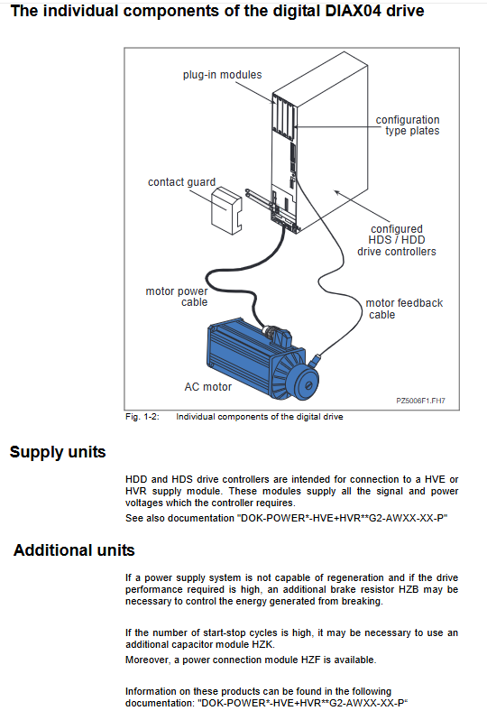
The core advantage of the DIAX04 drive system lies in its highly modular design. This system is not a single driving unit, but an organic whole composed of different functional modules working together. A complete DIAX04 driver package mainly consists of a power supply unit, a driver controller (HDS or HDD), and various additional units.
HDS (single axis drive) and HDD (dual axis drive) controllers serve as the execution terminals of the system, responsible for directly controlling the motors and monitoring their operating status. They are typically used in conjunction with HVE or HVR power supply modules, which provide all the signals and power voltages required by the driver. This design allows for flexible combination of multiple axes under a single power supply unit, greatly saving control cabinet space and simplifying wiring.
In addition, according to system requirements, it is also possible to integrate a braking resistor HZB (for processing braking energy), a capacitor module HZK (for energy buffering at high start stop frequencies), and a power connection module HZF. This "building block" component combination method endows the DIAX04 system with strong adaptability and scalability, which can meet various application requirements from simple point-to-point positioning to complex multi axis collaborative control.
Strict safety regulations and risk prevention and control
In industrial environments involving high pressure and high-speed movement, safety is always the top priority. The design and operation of the DIAX04 drive controller must strictly follow safety instructions to prevent personal injury and property damage.
1. Electrical contact protection and high voltage hazards
The drive controller contains high-voltage components exceeding 50V inside, and the capacitor still carries dangerous charges after power failure. According to the EN 50178 standard, strict grounding measures must be taken. Due to equipment leakage current exceeding 3.5mA, protective wires (PE) must use copper wires with a cross-sectional area of at least 10mm ² and be permanently connected to the power supply network. Before carrying out any maintenance work, the power must be disconnected and wait for at least 5 minutes until the capacitor is fully discharged and the voltage must be measured to confirm safety before touching. It is strictly prohibited to operate the equipment without installing grounding protection, and it is also strictly prohibited to use residual current operated protective devices (RCD) as direct protection for the driver. Overcurrent protection devices should be used to prevent indirect contact.
2. Dangerous sports and mechanical safety
Incorrect wiring, parameter settings, or sensor malfunctions may cause the motor to lose control and move. This danger may occur immediately after the device is started, or it may suddenly appear after long-term trouble free operation. Although the drive integrates monitoring functions internally, it must not rely solely on this function to ensure personnel safety. Superior monitoring measures must be implemented, such as installing protective fences, light curtains, etc., to ensure that personnel cannot enter dangerous areas by mistake. For the vertical axis, relying solely on the built-in brake of the motor is not enough. Additional mechanical locking, external braking, or balancing devices must be added to prevent heavy objects from falling after power failure.
3. Electromagnetic field and thermal surface protection
Electrical conductors and permanent magnets inside motors can generate strong magnetic fields, posing a serious health threat to individuals wearing pacemakers, metal implants, or hearing aids. Such personnel are strictly prohibited from entering the equipment operation, storage, or maintenance area. In addition, the drive housing, heat sink, and resistor may experience extreme high temperatures (up to 60 ° C) during operation. Operators must wait for the equipment to cool down for at least 10 minutes before coming into contact and wear protective gloves.
Product Technical Specifications and Model Analysis
1. HDS single axis drive controller
The HDS series is a basic single axis controller that covers multiple power levels from 40A to 300A (such as HDS02.2, HDS03.2, HDS04.2, HDS05.2). The model code has a clear logic, for example, in HDS03.2-W100N-HS01:
HDS stands for single axis drive.
03: Represents the serial number (corresponding to grades 75A-100A).
W: Represents internal air cooling.
100: Represents a rated current of 100A.
N: Represents no special version.
H: Representing the DIAX04 series.
S: Represents SERCOS interface (A represents analog interface).
HDS drives allow operation in environments ranging from+5 ° C to+45 ° C at rated data. If the ambient temperature or altitude exceeds the standard (altitude>1000 meters), the equipment must be downgraded according to the load factor to prevent overheating and damage. The power loss is mainly composed of control unit loss, configuration related loss, and power part loss. When calculating, it is necessary to consider the current intensity and switching frequency (4kHz/8kHz).
2. HDD Dual Axis Drive Controller
HDD02.2-W040N-HD32 is a special dual axis drive controller that can control two motors simultaneously. It integrates the SERCOS interface command communication module and provides an additional interface for each axis to connect to a 1Vpp sine wave signal incremental measurement system. This means that HDD drives can not only achieve high-speed digital communication through SERCOS fiber ring networks, but also directly connect to high-precision external measurement systems, making them particularly suitable for applications that require dual axis synchronization or high-precision positioning.
Electrical connection planning and interface detailed explanation
Correct electrical connections are the cornerstone of stable system operation. The DIAX04 driver controller provides rich and standardized interface terminals, each with its specific technical specifications.
1. Power supply and intermediate circuit connection (X1, X5)
The X1 terminal is an internally integrated bus connector that obtains the power required to control electronic devices from adjacent power supply units through a flat cable. The X5 terminal is a critical interface for connecting the DC bus (L+, L -) and the motor power supply (A1, A2, A3). According to different power levels, X5 supports wires with different cross-sectional areas (such as HDS02 supporting 0.2-4mm ², while HDS05 supporting 16-50mm ²), and has strict requirements for tightening torque (such as HDS02 being 0.5-0.6Nm and HDS04 being 4Nm). It is necessary to ensure that the polarity of the DC bus is correct, and the shielding layer of the motor connection wire must be reliably grounded through the XS1 terminal.
2. Communication and feedback interfaces (X2, X4, X7)
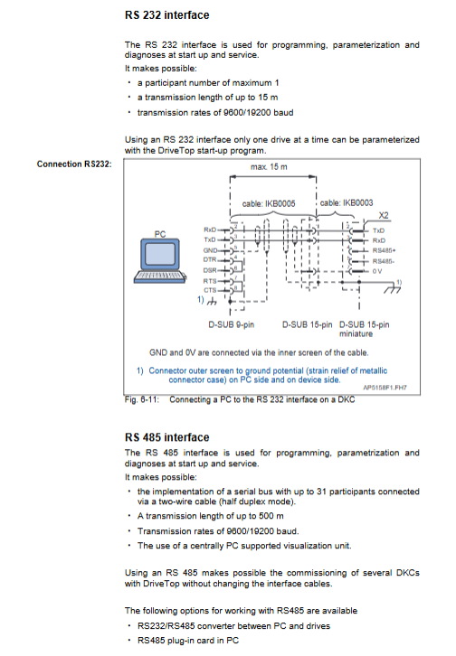
X2 (serial interface): Supports RS232 and RS485 modes, mainly used for debugging and parameterization. RS232 is suitable for direct connection between a single drive and a PC (up to 15m), while RS485 supports networking of multiple drives (up to 500m), which is convenient for centralized debugging with software such as DriveTop.
X4 (Motor Encoder 1): Used to connect HSF or parser feedback of Rexroth Indramat. If using other types of encoders, additional insertion modules need to be installed.
X7 (Motor Encoder 2): mainly found in HDD drives, used to connect 1Vpp sine wave measurement systems and provide high-resolution positioning interfaces.
3. Control and monitoring interfaces (X3, X6, X12)
X3 (Analog Output and Status): Contains two analog diagnostic outputs (AK1, AK2) for monitoring internal variables, as well as "Ready to Run" and "Start Blocked" contacts. When Bb is closed, it indicates that the driver is ready to connect to the main power supply; Startup blocking is a security mechanism to prevent accidental startup.
X6 (Braking and Temperature Monitoring): Used to connect motor holding brakes (BR+, BR -) and motor temperature sensors (PTC/NTC). The document emphasizes that the standard motor brake is not sufficient to ensure personnel safety, and an external 24V power supply must be provided with a maximum current not exceeding 2A.
X12 (External Input): Only present in HDD drives, used to connect reference switches, travel limit switches, measuring probes, and emergency stop signals. Its input circuit has a clear voltage level definition (high level 16-32V, low level 0-5.5V).
4. SERCOS fiber optic interface (X10/X11)
HDD drives come standard with SERCOS (Serial Real time Communication System) fiber optic interfaces. This interface complies with the IEC/EN 61491 standard and is connected to the upper control system through optical cables to achieve high-speed data transmission with strong anti-interference ability. Users can adjust the transmission power (-7dBm to 0dBm) and data rate (2 Mbaud or 4 Mbaud) through switch S4 to accommodate different cable lengths and transmission requirements.
Control cabinet design and thermal management planning
1. Size and installation
The installation of the DIAX04 driver controller must use a dedicated mounting rail (SUP-M01-HD). To ensure heat dissipation, sufficient space must be reserved around the device: at least 80mm at the top and at least 100mm at the bottom (taking into account the bending radius of the motor cable). When deploying in the control cabinet, high-power and high current drivers should be placed as close as possible to the power unit, and the loads on each axis should be evenly distributed to balance the power load.
2. Power loss and cooling system
The heat generated by the drive system is the core challenge in the design of the control cabinet. Power loss includes the total loss of power supply units, series switching devices, and each driver. When calculating, it is necessary to add the control electronic losses, configuration related losses (insertion module power consumption), and power part losses (obtained based on the average continuous current chart).
If the ambient temperature exceeds 45 ° C, a cooling system must be introduced. When using a cooling system, it is necessary to strictly prevent the harm of condensed water. The cooling device should be arranged in a location that avoids condensation water droplets falling or splashing onto electronic devices, and the set temperature of the cooling system should not be lower than 40 ° C to prevent condensation caused by the temperature inside the cabinet being lower than the ambient temperature. If the cabinet door is opened for debugging and then closed, it is necessary to ensure that the cooling system continues to operate until the temperature difference between the inside and outside is eliminated.
3. Electromagnetic compatibility (EMC) measures
In order to meet the RF interference limits of EN 55011, strict shielding measures must be taken:
The motor cable must use shielded cable and be grounded extensively on the driver side through XS1 terminal.
The power cord and signal/feedback cable must maintain a minimum distance of 100mm or be physically isolated using metal cable trays.
Avoid using varistors at inductive loads such as contactor coils. Instead, use RC damping modules or freewheeling diodes and install them as close to the load as possible.
Identification, transportation, and maintenance
1. Product identification
Each drive is equipped with a basic unit nameplate and a configuration nameplate. The basic unit nameplate is located on the top of the equipment and includes the product model; The configuration nameplate is inserted next to the insertion module, detailing the module models inserted in each slot of U1-U4 (such as DSS02.1M SERCOS interface, HSM software module, etc.). This is an important basis for quickly identifying equipment configuration, ordering spare parts, and conducting troubleshooting.
2. Transportation and Storage
During transportation and storage, attention must be paid to electrostatic protection. Components that are susceptible to damage from electrostatic discharge, such as plug-in modules, must be stored in conductive packaging. The allowed storage temperature range is -30 ° C to+85 ° C, and it must be kept dry, dust-free, and free from severe vibrations.
3. Service and Diagnosis
Rexroth Indramat provides comprehensive service support. When a malfunction occurs, the device generates error messages through the status display H1 and SERCOS interface. Users should record detailed model data, fault status, and software status of drives, motors, and gearboxes in order to contact the service hotline for efficient troubleshooting. Any repair work is only allowed to be performed by trained personnel or Rexroth Indramat customer service centers, and must be restarted and debugged after unit replacement.
- YOKOGAWA
- Reliance
- ADVANCED
- SEW
- ProSoft
- WATLOW
- Kongsberg
- FANUC
- VSD
- DCS
- PLC
- man-machine
- Covid-19
- Energy and Gender
- Energy Access
- Renewable Integration
- Energy Subsidies
- Energy and Water
- Net zero emission
- Energy Security
- Critical Minerals
- A-B
- petroleum
- Mine scale
- Sewage treatment
- cement
- architecture
- Industrial information
- New energy
- Automobile market
- electricity
- Construction site
- HIMA
- ABB
- Rockwell
- Schneider Modicon
- Siemens
- xYCOM
- Yaskawa
- Woodward
- BOSCH Rexroth
- MOOG
- General Electric
- American NI
- Rolls-Royce
- CTI
- Honeywell
- EMERSON
- MAN
- GE
- TRICONEX
- Control Wave
- ALSTOM
- AMAT
- STUDER
- KONGSBERG
- MOTOROLA
- DANAHER MOTION
- Bentley
- Galil
- EATON
- MOLEX
- Triconex
- DEIF
- B&W
- ZYGO
- Aerotech
- DANFOSS
- KOLLMORGEN
- Beijer
- Endress+Hauser
- schneider
- Foxboro
- KB
- REXROTH
- YAMAHA
- Johnson
- Westinghouse
- WAGO
- TOSHIBA
- TEKTRONIX
- BENDER
- BMCM
- SMC
- HITACHI
- HIRSCHMANN
- XP POWER
- Baldor
- Meggitt
- SHINKAWA
- Other Brands
- UniOP
- KUKA
- IBA
- Beckhoff
-
Basler Electric DECS-250-CN1SN1N Automatic Voltage Regulator for Generator Excitation Control
-
ADLINK CPCI-6860A - 51-31310-OB10 industrial motherboard CompactPCI SBC
-
ADLINK AmITX-SL-G-H110 - 51-7A104-0A30 Mini-ITX Industrial Motherboard
-
ADLINK PXI-2005-003 - CPCI Industrial PC Data Acquisition Card Multi-Function DAQ
-
ADLINK DININ-814M - 51-14032-0A3D SCSI-100P cable connection Interface Terminal Board
-
ADLINK CPCI-3920NA/C2D15/M1G - 3U CompactPCI Intel Core 2 Duo Single Board Computer
-
ADLINK PCIE-8560 - 51-18014-0A20 Communication Card High Speed DAQ
-
ADLINK PCI-C154+ - Motion Control Card 4-axis Motion Controller Board
-
ADLINK PCI-RTV24 - image capture card Analog Video Frame Grabber
-
ADLINK NuPRO-842LV/P - 51-41360-0B30 Industrial Motherboard CPU Board
-
ADLINK cBP-3208/3208R - CPCI Board 3U 8-Slot CompactPCI Backplane
-
ADLINK PCI-8164 - 4-Axis Motion Controller PCI Card 51-12406-0A40
-
ADLINK PCIe-GIE64+ - 4-CH GigE Vision PoE+ Frame Grabber Video Capture Card
-
ADLINK CPCI-6860 / 6860A - CompactPCI Dual Xeon Single Board Computer
-
ADLINK IEC-915GV - REV 1.1 Industrial motherboard CPU Board
-
ADLINK ND-6520 - Technology RS-232 to RS-422RS-485 Converter NuDAM Module
-
ADLINK RTV-24 / PCI-MP4S - 51-12519-1C30 4-Channel Real Time Video Capture Board
-
ADLINK cPCI-6910 / cPCI-6910AM/M1G - cPCI-6910AM/DXL16/M1G/S80G(G)-3120 BOARD CompactPCI SBC
-
ADLINK NUPRO-A40H - Linghua 51-41807-1A30 Industrial Control Computer Motherboard
-
ADLINK USB-3488A - USB to GPIB INTERFACE USB-3488A(G) Controller Module
-
ADLINK PCI-8134A - motion control card 4-Axis Controller Card
-
ADLINK PCI-7432 - Board 32-Channel input / 32-output Isolated Digital I/O PCI Card
-
ADLINK PCI-8134A - 51-12421-0A10 motion controller card tested
-
ADLINK LPCIe-7230 - 32 CH Isolated Input/output Card 2 Interrupts Low Profile PCIe
-
ADLINK NuPRO-E340 - industrial computer motherboard 51-47807-0A30 PICMG 1.3 SHB
-
ADLINK PCI-7434 - High-speed Digital Acquisition Card 64-CH Isolated DO Card
-
ADLINK NuPRO-E330 - 51-41805-0A20 Indsutrial Board SHB Single Board Computer
-
ADLINK PCI-7248 - OPTO-22 48 CHANNEL DIO DIGITAL TTL/DTL I/O 51-12006-0A40 GP
-
ADLINK PCI-8134 - Motion control card 4-Axis Controller Card
-
ADLINK AMP-208C - Movimiento Control Tarjeta 51-12420-1A20 W/Expansión & Breakout
-
ADLINK PCI-8164 - 51-12406-0A40 PCB Board 4-Axis Motion Controller Card
-
ADLINK DIN-68Y-SGII / DIN-68M-J3A - Terminal Board Connector Interface Block
-
ADLINK PCIe-7432 - Technology 51-18402-0A10 PCIe Card With High Input Range
-
ADLINK PCI-8144 / PCI-8144N - Motion control card 4-Axis Stepper Controller Card
-
ADLINK HSL-HUB3/REPEATER - HIGH SPEED LINK EXTENSION MODULES Distributed Hub Module
-
ADLINK ND-6017 - Data Logging + Acquisition 8CH A/D input Mod NuDAM Module
-
ADLINK LPCIe-7250 - data acquisition card Low Profile 8-CH Relay Output Card
-
ADLINK PCI-7432 - I/O card 64-CH Isolated Digital Input Output PCI Card
-
ADLINK IMB-M43H - industrial control computer motherboard Q87 Chip Micro-ATX
-
ADLINK MP-C154 - Motion control Card 4-Axis Motion Controller Board
-
ADLINK PCI-RTV24 - image capture card Video Frame Grabber Card
-
ADLINK PCI-7250 - 8-CH Relay Output & 8-CH Isolated DI Card
-
ADLINK PCI-6308V - 8-CH 12-Bit Isolated Analog Output PCI Card PCB-I-E-1148=6EX2
-
ADLINK PCI-7248 - capture card 48-CH Opto-22 Compatible DIO Card
-
ADLINK HSL-AI16A02-M-VV - Analog Input Output Distributed Module
-
ADLINK NuPRO-A301 - Rev:1.4 NUPRO-A301 PICMG Full-Size Single Board Computer
-
ADLINK PCI-6208V-GL - 8-CH Voltage Analog Output PCI Card
-
ADLINK PCI-8134A - 51-12421-0A10 4-Axis Motion Controller Card
-
ADLINK MNET-S23 - TECHNOLOGY MNET S23 - SERVO DRIVER CONTROL MODULE
-
ADLINK M-342 - ATX I3 I5 I7 Q67 Industrial Motherboard
-
ADLINK NUPRO-780 - Industrial Motherboard CPU Board PICMG SBC
-
ADLINK MP-C154 / MP-C152 - 4-Axis Motion Control Card Pulse-Train Controller
-
ADLINK NuPRO-935A/LV10B0 - Motherboard 51-41802-0A10 GP w/RAM Industrial Control Board
-
ADLINK MP-C154 - Motion control card 4-Axis Motion Controller Mainboard
-
ADLINK PCI-7250 - PCI Acquisition Card 8-CH Relay Output Isolated DI Card
-
ADLINK ACL-7124 - Technology Inc.24 DIO Card Digital Input Output Card
-
ADLINK PCI-8554 A2 - Timer/Counter Data Acquisition Card
-
ADLINK DIN-825-GP4 - Terminal Block Interface Board Breakout Module
-
ADLINK NuPR0-761 - REV:1.1 Industrial motherboard Full-Size PICMG SBC
-
ADLINK MXE-1401/M8G (G) - Matrix Fanless Embedded Computer Industrial PC
-
ADLINK HSL-DI16DO16-UD-NN - Digital 16 Channel I/O Mod Distributed I/O Module
-
ADLINK ND6520 - NUDAM INTELLIGENT DA&C MODULE RS232-RS-422/RS485 CONVERTOR
-
ADLINK NUPRO-761 - REV:1.1 Industrial Motherboard CPU Board
-
ADLINK AMP-208C - Motion Control Card 51-12420-1A20 DSP-based 8-axis
-
ADLINK NuPRO-A301REV 1.4 - with packaging industrial computer motherboard PICMG SBC
-
ADLINK PCM-9112+ - 51-12300-0A2 industrial motherboard Multi-Function DAQ PC/104 Module
-
ADLINK PCM-7250+ - 8-CH Relay Outputs & 8-CH Isolated DI Module PC/104
-
ADLINK PCI-RTV24 - Image capture card Analog Video Frame Grabber
-
ADLINK PCI-8134 - Motion Controller PCI Card 4-Axis Controller Board
-
ADLINK PCI-7432 - Isolated Digital I/O PCI Card
-
ADLINK PCI-8554 A2 - acquisition card Timer/Counter Card
-
ADLINK PCI-8132 - Rev.A2 2-Axis Servo & Stepper Motion Controller Card
-
ADLINK PCI-8132 - Data Acquisition card 2-Axis Motion Controller Card
-
ADLINK EBP-13E4 - 51-46703-0A30 Industrial Backplane Board Passive Backplane
-
ADLINK PCI-800L - Electronic Card Interface Controller Card
-
ADLINK PCIe-GIE72 - 51-18531-0A10 PCB Board GigE Vision Frame Grabber
-
ADLINK DAQ-2010(G)-OOBO - Simultaneous-Sampling Multi-Function DAQ Card
-
ADLINK PCI-9112 - REV.B1 Multifunction DAQ Card Data Acquisition Card
-
ADLINK PCI-7230 - 51-12003-DA60 32-CH Isolated Digital I/O Card
-
ADLINK PCI-7432 - Data Acquisition Card Isolated Digital I/O PCI Card
-
ADLINK ETX-AT-N270-18/LXE - 51-71111-0A20 ETX CPU Module Motherboard
-
ADLINK HSL-DI32-UD-N - DIGITAL INPUT 32 POINTS MODULE Distributed I/O
-
ADLINK AMP-204C - Motion Control card DSP-Based 4-Axis Advanced Controller
-
ADLINK MNET-4XMOG-0050 - Four-axis Motion Controller Distributed Motion Module
-
ADLINK AMP-204C - Motion control card DSP-Based 4-Axis Pulse-Train Controller
-
ADLINK PCI-7442 - Switch card 64-Channel Datalogging & Acquisition Card
-
ADLINK M-302 - Industrial control motherboard ATX PC Board
-
ADLINK NUPRO-852 / NUPRO-852LV - Industrial motherboard Single Board Computer
-
ADLINK PCI-8134 - REV.B1. 4-Axis Motion Controller Card
-
ADLINK PCI-GIE62 + - 51-18502-0A20 2-CH GigE Vision Frame Grabber PoE Card
-
ADLINK PCI-MPG24 - 51-12523-0B20 MPEG4 Card Video Compression Hardware
-
ADLINK HSL-TB32-M-DIN - 32-CH I/O TERMINAL W/ HSL-AI16AO2-M-VV MODULE
-
ADLINK PCI-M114-GL - PCB Ver 2.1 Motion Controller Axis Card
-
ADLINK IMB-M40H - SYM76996H61 motherboard Industrial Computer Mainboard
-
ADLINK NUPRO-A40H - 51-41807-1A20 industrial control motherboard H61 Chip
-
ADLINK PCI-M114-GL - Axis Card Data Acquisition Card PCB VER2.2 Motion Controller
-
ADLINK PCI-8134 - Motion Controller PCI Card 4-Axis Controller Board
-
ADLINK PCI-8102 - Motion control card 2-Axis Servo & Stepper Controller
-
ADLINK NuPRO-841REV:3.0 - motherboard Industrial Control PC Board
-
ADLINK HSL-TB32-U-DIN REV A1 - Breakout Terminal Board Field I/O Module
-
ADLINK AMP-204C - Motion Control card DSP-Based 4-Axis Pulse-Train Controller
-
ADLINK NUPRO-A40H - 51-41807-1A20 industrial control motherboard H61 PC Board
-
ADLINK PCI-6308A / PCI-6308V - 51-12202-0A50 Isolated Analog Output Card
-
ADLINK AMP-204C - DSP-Based 4-Axis Advanced Pulse-Train Motion Controller
-
ADLINK PCI-7434 - Technology 64-Channel Isolated Digital I/O PCI Cards
-
ADLINK CPCI-6840 / CPCI-6840V / PM16/M1G-12G0 - CompactPCI Single Board Computer CPU Module
-
ADLINK PCIE-GIE74 - Motherboard Video Capture Card 51-18531-0A10 Frame Grabber
-
ADLINK NuPRO-E330 - industrial computer equipment motherboard Control Mainboard
-
ADLINK AMP-208C / 51-12420-1A20 - Motion Control Card W/ Expansion & Breakout Board
-
ADLINK HPCI-14S12U - industrial computer baseboard Passive Backplane 14 Slots
-
ADLINK PCI-8164 - 4-Axis Motion Controller PCI Card W/ 1x Cable, 1x Breakout Box
-
ADLINK PCIe-RTV24 - 51-18016-0A20 Image Acquisition Video Capture Card
-
ADLINK M-342 - 5 PCI ATX Motherboard Industrial PC Mainboard
-
ADLINK PCI-FIW64 - 4/2 Channel IEEE1394B Image Capture Card FireWire Frame Grabber
-
ADLINK PCI-7432 - digital IO card 64-CH Isolated Digital Input Output Card
-
ADLINK 51-12001-0C20 - Circuit Board PCI-7200 Data Acquisition Controller Card
-
ADLINK PXI-3920 - PXI 3U cPCI Industrial Controller Embedded System CPU Board
-
ADLINK NuPRO-841REV:2.0 - motherboard Industrial Control PC Board
-
ADLINK NuPro-E330 - 51-41805-0A20 PCB Industrial Control Computer Motherboard
-
ADLINK PCI-RTV24 - Image capture card Analog Video Frame Grabber
-
ADLINK PCI-7442 - Switch card 64-Channel Datalogging & Acquisition Card
-
ADLINK HPX-13S4 - device baseboard Passive Backplane Riser Card
-
ADLINK PCI-9112 REV A.1 - Multi Function DA&C Board Data Acquisition Card
-
ADLINK PCI-7248 - 51-12006-0A40 Card Control 48-CH Digital I/O Module
-
ADLINK CPCI-6860 / 6860A - motherboard CompactPCI Dual Xeon Single Board Computer
-
ADLINK DPAC-3020-11(G) - Embedded PC Automation Controller Machine Control Board
-
ADLINK NuPRO-841 REV:1.0 - industrial control motherboard CPU Board
-
ADLINK MNET-4XMOG-0050 - Four-axis Motion Controller MNET Motion Control Card

K-JIANG

Add: Jimei North Road, Jimei District, Xiamen, Fujian, China
Tell:+86-15305925923