

K-WANG


Kollmorgen S700 series digital servo amplifier
Kollmorgen S700 series digital servo amplifier
Basic Information
Core positioning: The S700 series is a high-performance digital servo amplifier that supports 208-480VAC three-phase input (S7xx0 model) or 110-230VAC single/three-phase input (S7xx6 model), integrates CANopen and EtherCAT bus interfaces, and comes standard with dual channel STO (Safe Torque Off) function (up to SIL CL3/PLe level). Additional functions such as PROFIBUS, SERCOS, DeviceNet can be achieved through expansion cards. It is recommended to use it with Kollmorgen motors and direct connection to loads is prohibited for operation.
Version and hardware adaptation: The document corresponds to hardware version 02.20 and requires firmware version ≥ 5.18 (ND1/NDO data structure). The functional differences between different hardware versions mainly lie in DC bus parallel capability and memory compatibility (support for memory cards at 02.10 and above). For older versions (such as 00.20/01.21), reference should be made to the corresponding manual revision.
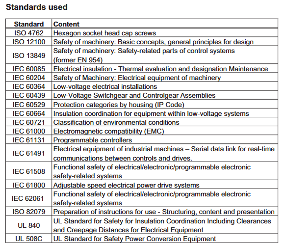
Core technical characteristics and classification of amplifiers
(1) General Technical Parameters
Category parameter item specification
Power characteristic input voltage S7xx0:3 × 208V-10%~3 × 480V+10% (50/60Hz); S7xx6:1×110V-10%~3×230V+10%(50/60Hz)
The maximum DC bus voltage is 900VDC (S7xx0) and 455VDC (S7xx6), with an undervoltage fault of 100VDC and an overvoltage fault of 900VDC (S7xx0)/455VDC (S7xx6)
Rated output current of 1.5-24ARMS (e.g. S70102 is 1.5ARMS, S72402 is 24ARMS), peak value of 4.5-72ARMS (lasting for 2 seconds)
Motor adaptation motor types: synchronous servo motor, asynchronous motor, DC motor, linear motor
Motor inductance range S7xx0 (320VDC bus): 50-200mH; S7xx6 (160VDC bus): 7-30mH
Feedback supports rotary transformers, SinCos encoders (EnDat 2.1/2.2, BiSS-C, HIPERFACE), incremental encoders (ROD), SSI encoders
Control characteristic switch frequency 8kHz (output stage)
Control cycle current loop 62.5 μ s, speed loop 62.5 μ s, position loop 250 μ s (optional 125 μ s)
Safety function dual channel STO (SIL CL3/PLe), supporting extended safety functions such as SS1/SS2/SOS/SLS (requires safety expansion card)
Environmental adaptability: Operating temperature range of 0-40 ℃ (rated working condition), with a reduction of 2.5%/℃ required for 40-55 ℃
Storage temperature -25-70 ℃
Humidity 95% relative humidity (no condensation)
Altitude ≤ 1000m (no downgrading), downgrading 1.5%/100m for 1000-2500m
Protection level IP20 (IEC 60529)
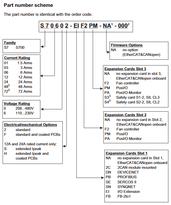
(2) Model classification and key parameters
The S700 series is divided into two sub series based on rated output current and input voltage, with the following differences in core parameters:
Subseries models rated output current (ARMS) peak output current (ARMS/2s) input voltage DC bus voltage (VDC) weight (kg) heat dissipation method
S7xx0 (three-phase input) S70102 1.5 4.5 3 × 208-480VAC 900 4.4 Forced air cooling
S70302 3 9 3 × 208-480VAC 900 4.4 forced air cooling
S70602 6 18 3 × 208-480VAC 900 4.4 forced air cooling
S71202/S7120S 12 24/30 3 × 208-480VAC 900 5.5 forced air cooling
S72402/S7240S 24 48/72 3 × 208-480VAC 900 5.5 forced air cooling
S7xx6 (single/three-phase input) S70162 1.5 4.5 1 × 110-230VAC/3 × 110-230VAC 455 4.4 Forced air cooling
S70362 3 9 1 × 110-230VAC/3 × 110-230VAC 455 4.4 Forced air cooling
S70662 6 18 1 × 110-230VAC/3 × 110-230VAC 455 4.4 Forced air cooling
S71262/S7126S 12 24/30 1 × 110-230VAC/3 × 110-230VAC 455 5.5 forced air cooling
S72462/S7246S 24 48/72 1 × 110-230VAC/3 × 110-230VAC 455 5.5 forced air cooling
(3) Optional configurations and expansion cards
Core Function Expansion
Security Expansion Card: Slot 3 can be installed with S3 (S1-2, SIL CL3/PLe) or S4 (S2-2, SIL CL2/PLd) security cards, supporting security functions such as SS1/SS2/SOS/SLS/SPLP. The S3 card also supports safety brake control (SBC) and brake testing (SBT).
Communication expansion card: Slot 1 supports PROFIBUS(DE-106712)、SERCOS(DE-90879)、DeviceNet(DE-103571)、SynqNet(DE-200073),Slot 2/3 Supports PosI/O (DE-200881) to expand high-precision I/O interfaces.
Feedback extension card: FB-2to1 (DE-201664) supports simultaneous connection of digital primary feedback and analog secondary feedback, solving compatibility issues with multiple feedback devices.
Heat dissipation optimization: Option F2 (Slot 2/3) is a controllable fan that automatically adjusts the speed based on temperature (55-75 ℃) and braking power (20-45W) to reduce noise (default fan noise is 43-65dB (A)).
Storage and Communication: Supports MMC/SD memory cards (DE-201257), which can store firmware and parameters, enabling fast configuration of multi axis systems; Standard RS232 (X6), CANopen (X6), EtherCAT (X7) interfaces, EtherCAT supports CAN over EtherCAT protocol and automatically detects bus type.
Installation and wiring specifications
(1) Mechanical installation requirements
Installation preparation
Installation surface: It should be made of conductive material (such as galvanized steel plate) with a flatness error of ≤ 0.1mm. It should be fixed with M5 hexagon socket screws (torque 0.7-0.8Nm). The installation size of S701-S712 is 345 × 70 × 243mm (H × W × D), and S724 is 348 × 100 × 243mm. A heat dissipation space of ≥ 25.4mm should be reserved around it. It is prohibited to install it under a heat source (such as a frequency converter).
Temperature control: If the ambient temperature exceeds 40 ℃, forced air cooling (wind speed ≥ 2m/s) should be added. When the temperature of the heat sink exceeds 80 ℃, the amplifier will overheat and shut down (fault F01). It is recommended to use the S724 model with a cold plate (heat dissipation area ≥ 0.1m ²).
Fan installation
S701-S712 fan: Pinch the long side of the fan housing and pull it down. When installing, align it with the green connector and push it into the buckle lock.
S724 fan: Pinch the short side of the fan housing and pull it down. When installing, make sure the connector is aligned with the socket and press it until the buckle is fixed. The fan has no independent wiring and can be powered through the internal connector.
(2) Electrical wiring specifications
Wiring safety and sequence
Power off operation, ensure capacitor discharge (≥ 8 minutes after power off, measure DC bus voltage<60V), all power cables (motor/power) and control cables (feedback/I/O) need to be separately shielded, and the shielding layer should be grounded 360 ° through the amplifier front panel or metal connector (low impedance).
The distance between power cables and control cables should be ≥ 200mm to avoid cross interference; When the length of the motor cable exceeds 25m, Kollmorgen 3YL/3YLN motor choke coils should be connected in series (such as S70102 with 4 × 1mm ² cable) to reduce leakage current and EMI interference.
Core interface definition
Power interface (X0): S7xx0 model L1/L2/L3 connected to three-phase live wire, PE connected to protective ground; S7xx6 single-phase connection L1/N, three-phase connection L1/L2/L3, PE wire section ≥ 10mm ² or dual PE wiring, external slow melting fuse needs to be configured (such as S70102 with 6A/600V, S72402 with 30A/600V).
Motor interface (X9): U2/V2/W2 is connected to the three-phase winding of the motor, PE is connected to the motor casing, BRAKE+/BRAKE - is connected to a 24V brake (only with a brake motor), the brake current is ≤ 2A, and a separate freewheeling component (such as a varistor) needs to be configured.
Safety interface (X4A/X4B): STO1 Enable (X4B/6) and STO2 Enable (X4A/3) are connected to external safety circuits (24V/33-40mA). In dual channel configuration, safety relay outputs need to be connected separately to ensure SIL CL3 level. When not in use, they need to be short circuited to+24V.
Feedback interface (X1/X2): X2 is the rotary transformer interface (9-pin SubD), R1/R2 is the reference signal, S1/S2/S3/S4 is the sine/cosine signal; X1 is an encoder interface (15 pin SubD) that supports protocols such as EnDat/BiSS/HIPERFACE. The FBTYPE parameter needs to be selected based on the feedback type (e.g. EnDat 2.2 is set to 32/34).
Typical wiring scheme
Three phase power supply (S70602): L1/L2/L3 connected to 3 × 400VAC, PE connected to cabinet ground, X0 terminal tightened with a torque of 0.7-0.8Nm, power supply side connected in series with 10A slow melting fuse (UL class RK5) to avoid damage from surge current.
Motor and brake (with brake motor): X9 terminal U2/V2/W2 is connected to the motor winding, BRAKE+is connected to 24V power supply, BRAKE - is connected to amplifier X9/1, the brake control wire uses shielded twisted pair (such as 2 × 0.75mm ²), the shielding layer is grounded at both ends, and additional mechanical braking is required for vertical axis applications (brake is only used for parking and frequent braking is prohibited).
STO safety circuit (dual channel): STO1 Enable (X4B/6) is connected to the normally closed contact of safety relay K1, STO2 Enable (X4A/3) is connected to the normally closed contact of safety relay K2, and the relay coil is controlled by the emergency stop button. When the emergency stop is triggered, the STO signal is disconnected, and the amplifier cuts off the motor torque (fault F27).
Security Features and System Configuration
(1) STO security function (core security feature)
Function definition and level
STO (Safe Torque Off) achieves no torque output of the motor by blocking the triggering pulse of the power transistor, which complies with EN 60204-1 stop category 0 (uncontrolled shutdown). The single channel configuration (STO1/STO2 series) reaches SIL CL2/PLd, and the dual channel+cycle test (safety controller monitoring feedback signal) reaches SIL CL3/PLe. The PFH_D is 1.04E-09 1/h, and the MTBF is 20 years.
Wiring and Testing
Single channel wiring: STO1 Enable and STO2 Enable are connected in series and then connected to a safety relay output. The reference ground is XGND (X4B/5), with an input voltage of 20-30VDC and a current of 33-40mA. When disconnected, the amplifier displays "- S -" and the motor has no torque.
Functional testing:
When the motor is stationary (the enable signal is valid), disconnect the STO input, the amplifier should immediately cut off the torque, display fault F27, and the BTB/RTO contact (X3B/14-15) is disconnected.
Reset STO input, use Fault Reset input (X3A/18) or software reset to restore the amplifier to normal state, with a test cycle of ≤ 8 hours (SIL CL3 requirement).
(2) System configuration (software and hardware settings)
Software Configuration (DRIVE GUI. EXE)
Installation and Connection: Supports Windows 2000/XP/Vista/7, connects PC and amplifier X6 interface through RS232 cable (P7S2-232-9D), baud rate 38400bps, data bit 8, even check, stop bit 1, software automatically recognizes amplifier model and firmware version.
Core configuration module:
Motor configuration: Select the motor model (such as AKM series) from the database, or manually input parameters such as rated current, torque constant, inductance, etc., and perform the "Motor Probe" to detect the motor inductance and optimize the current loop gain.
Security configuration: The STO function requires setting the STO Status output (such as X3A/6) and associating it with the security controller through the ASCII command OxMODE70 to achieve periodic testing; The security card S3/S4 needs to be configured with SS1 activation signal (X30/1) and reset signal (X30/20) to ensure the correct triggering timing of the security function.
Sports configuration: Set the electronic gear ratio for the position ring (e.g. set PGEAR1=2 and PGEAR0=1 for a 1:2 gearbox), gain for the speed ring (Kp=0.5-2.0, Tn=0.01-0.1s), and automatically optimize control parameters through "Autotuning" to reduce tracking errors (fault F03).
Hardware switch configuration
Address and baud rate: Set the CANopen station address (1-99) and baud rate (10-1000kbit/s) through the amplifier front-end buttons. After setting, restart the 24V power supply to take effect. The baud rate encoding is as follows: "25" corresponds to 250kbit/s, and "50" corresponds to 500kbit/s.
Expansion card recognition: After inserting the expansion card into Slot 1/2/3, the amplifier will automatically recognize it when powered on. The function can be configured through the DRIVE GUI "Expansion Card" interface (such as setting the PROFIBUS address to 3 and the baud rate to 1.5Mbit/s). If the expansion card is not recognized, it is necessary to check whether it is installed properly (card buckle locking).
- YOKOGAWA
- Reliance
- ADVANCED
- SEW
- ProSoft
- WATLOW
- Kongsberg
- FANUC
- VSD
- DCS
- PLC
- man-machine
- Covid-19
- Energy and Gender
- Energy Access
- Renewable Integration
- Energy Subsidies
- Energy and Water
- Net zero emission
- Energy Security
- Critical Minerals
- A-B
- petroleum
- Mine scale
- Sewage treatment
- cement
- architecture
- Industrial information
- New energy
- Automobile market
- electricity
- Construction site
- HIMA
- ABB
- Rockwell
- Schneider Modicon
- Siemens
- xYCOM
- Yaskawa
- Woodward
- BOSCH Rexroth
- MOOG
- General Electric
- American NI
- Rolls-Royce
- CTI
- Honeywell
- EMERSON
- MAN
- GE
- TRICONEX
- Control Wave
- ALSTOM
- AMAT
- STUDER
- KONGSBERG
- MOTOROLA
- DANAHER MOTION
- Bentley
- Galil
- EATON
- MOLEX
- Triconex
- DEIF
- B&W
- ZYGO
- Aerotech
- DANFOSS
- KOLLMORGEN
- Beijer
- Endress+Hauser
- schneider
- Foxboro
- KB
- REXROTH
- YAMAHA
- Johnson
- Westinghouse
- WAGO
- TOSHIBA
- TEKTRONIX
- BENDER
- BMCM
- SMC
- HITACHI
- HIRSCHMANN
- XP POWER
- Baldor
- Meggitt
- SHINKAWA
- Other Brands
- other brands
- UniOP
- KUKA
- IBA
-
Hirschmann RS20-0800T1T1SDAEHC09.1.00 Industrial Ethernet Switch Managed Network Switch for Factory Automation and Industrial Communication Systems
-
Omron C500-NC103-E PLC Position Control Module Industrial Automation System for High Precision Machine Control and Factory Integration
-
Omron R88D-HT10 PLC Servo Drive Industrial Motion Control Unit for High Precision Automation Systems and Industrial Machinery Applications
-
Omron R88D-HS22 R88D-H310G R88M-H1K130 Servo Drive System High Precision Motion Control Package for Industrial Automation Applications with Cable
-
Schneider ATV212HD22N4S Variable Speed Drive Industrial Inverter for HVAC Motor Control Energy Efficient Automation System Solution
-
TOYO KEIKI EH-R YH-212 P:CARD5 Industrial Control Card Precision Measurement and Signal Processing Module for Automation Systems
-
Mitsubishi AJ71QLP21G PLC Module Industrial Communication and Control Unit for Factory Automation and System Integration Solutions
-
Mitsubishi A1SX81 Digital Input Module PLC Local Unit for Industrial Automation Signal Acquisition and High Reliability Control Systems
-
Omron F350-L100E Image Processing Unit Industrial Vision System for Automated Inspection and Quality Control Applications
-
Omron NS12-TS01B-V2 HMI Touch Screen Operator Panel Industrial Automation Interface for Machine Control and Visualization Systems
-
Siemens 6SE7090-0XX84-0AG1 CU3 Closed Loop Control Module Industrial Drive and Automation Control System Component
-
ABB P-HC-BRC-40000000 Harmony Bridge Controller Industrial Automation Communication and Integration Module
-
Siemens 6SE7038-6EK84-1JC2 IGD8 Gate Driver Module for Industrial Drive Systems and High Power Inverter Control Solutions
-
Omron B7AM-8B16 PLC Digital I/O Module Expansion Unit for Industrial Automation Control Systems and Signal Processing
-
Omron R7M-A10030-BS1 SmartStep Servo Motor 100W 200V Industrial Motion Control System with Brake Function for Precision Automation
-
B&R 4PP035.0300-01 Operation Panel Industrial HMI Interface for Machine Control, Process Monitoring and Automation Visualization Systems
-
B&R 3AM050.6 PLC Module for Industrial Automation Control System Processing and Machine Control Unit
-
ABB G3ENa HENF450268R2 Industrial Automation Control Module High Performance Processing and Distributed System Interface Unit
-
ABB P5EAa HENF206350R2 Industrial Automation Control Module Advanced Processing and High Reliability System Interface Unit
-
ABB O3EC HENF442581R1 Industrial Automation Control Module High Precision Signal Processing and Distributed System Interface Unit
-
ABB O3EHa HENF315087R2 Industrial Automation Control Module Advanced Signal Processing and System Interface Unit
-
ABB E3ED Industrial Automation Control Module High Stability Signal Processing and Distributed System Interface Unit
-
ABB O3ED Industrial Automation Control Module Signal Processing and Distributed System Interface Unit
-
ABB E3EP HENF315276R1 Industrial Automation Control Module High Precision Signal Processing and System Interface Unit
-
ABB O3EGb HENF315118R2 Industrial Automation Control Module Advanced Signal Processing and System Interface Unit
-
ABB O3ES HENF445789R1 Industrial Automation Control Module Advanced Signal Processing and Distributed System Interface Unit
-
ABB E3EB HENF315129R1 Industrial Automation Control Module High Stability Signal Processing Unit
-
ABB G3ESa HENF318736R1 Industrial Control Module Advanced Automation System Interface Processing Unit
-
ABB 8025-235 Industrial Control and Measurement Module Automation Signal Processing Unit
-
ABB REG216 Industrial Generator Protection and Control System Advanced Power Automation Relay Unit
-
ABB PU512V2 3BUR001401R1 Industrial Processor Unit High Performance Automation Control Module
-
ABB LDMUI-001 61320946C Industrial Drive Control Interface Module High Performance Automation Communication Unit
-
ABB 216NG61A HESG441633R1 HESG216875/K Industrial Control Module Advanced Automation Processing Unit System Interface
-
ABB PFTL201C 50KN 3BSE007913R50 High Precision Load Cell Industrial Tension Measurement and Force Control Sensor Unit
-
ABB RED670 High Performance Line Differential Protection Relay Industrial Power System Protection Unit
-
ABB PP825A 3BSE042240R3 Industrial Panel Controller Advanced Automation HMI Processing Unit
-
ABB SCYC51020 58052582/G Industrial Control and Communication Module High Stability System Interface Unit
-
ABB AO2000 LS25 Industrial Gas Analyzer System High Precision Emission Monitoring and Process Control Unit
-
ABB LM80 Industrial Measurement and Signal Processing Module Automation System Data Acquisition Unit
-
ABB PFEA113-20 3BSE028144R0020 Industrial Tension Control Module High Precision Measurement Unit
-
ABB PM803F 3BDH000530R1 Industrial Controller CPU Automation System Processing Unit
-
ABB SD822 3BSC610038R1 Power Supply Module Industrial Automation System Stable Energy Unit
-
ABB PCD235B1101 3BHE032025R1101 Industrial Control Module High Performance Automation Processing Unit
-
ABB AZ20/112112221112E/STD Industrial Gas Analyzer Control and Monitoring System High Precision Measurement Unit
-
ABB KP3000 Advanced Industrial HMI Panel Operator Control Interface System Unit
-
ABB KP2500 Industrial HMI Operator Panel Human Machine Interface Control Display Unit
-
ABB UFD203A101 3BHE019361R0101 Industrial Interface Control Module Automation Communication Unit
-
ABB GVC736CE101 3BHE039203R0101 Industrial Drive Control Processing Unit High Performance Automation Controller
-
ABB UAD142A01 3BHE012551R0001 Industrial Control and Automation Interface Module High Stability Processing Unit
-
GE HE693STP110 Stepper Motor Control Module for Industrial PLC Systems
-
GE HE693STP104AX Stepper Control Module for PLC Automation System
-
GE DS200TCQAG1BHF Turbine Control Module
-
GE DS200ADGIH1AAA Analog Input Control Board
-
ABB CAI04 Analog Input Module for Industrial Automation System Signal Acquisition and Process Control Interface Unit Replacement
-
ABB FET3251C0P184C0H2 Industrial Control Interface Module for Automation System Signal Processing and Power Management Unit Replacement
-
ABB 5SHY35L4503 IGCT Power Module for Industrial Drive System Inverter Control and High Power Conversion Unit Replacement
-
ABB PM866-2 3BSE050201R1 AC 800M Controller CPU Module for Industrial Automation System Control Processing and Distributed Control System Core Unit
-
ABB CP405 A0 1SAP500405R0001 HMI Touch Panel for Industrial Automation Operator Interface Display Control and Monitoring System
-
ABB R474A11XE HAFAABAAABE1BCA1XE Power Supply Module for Industrial Automation System Control Cabinet Energy Distribution and Interface Support Unit
-
GUTOR OP6257 Industrial Power Control Module | Reliable UPS System Component
-
ABB REF542PLUS 1VCR007346 Protection Relay for Substation Automation Power Distribution Control and Electrical Fault Protection System
-
ABB REF542PLUS 1VCF752000 Protection Relay for Substation Automation Power System Control and Electrical Fault Detection Unit
-
ABB PPD113B03-26-100100 3BHE023584R2625 Drive Control Board for Industrial Automation Excitation System and Power Electronics Control Module
-
ABB PCD232A 3BHE022293R0101 Industrial Drive Control Processing Module Power Electronics Interface Unit
-
ABB PFEA113-65 3BSE050092R65 Tension Control Module Industrial Automation Measurement Unit
-
ABB XVC767AE102 3BHB007209R0102 Industrial Drive Control Board Power Electronics System Module
-
ABB CI857K01 3BSE018144R1 Communication Interface Module for Industrial Automation System Control Network Integration and Data Exchange Gateway Unit
-
ABB 3ASC25H219B DATX133 Advanced Signal Interface Module for Industrial Automation System Multi-Channel Communication and Control Data Optimization Unit
-
ABB 3ASC25H214 DATX130 High-Speed Signal Interface Module for Industrial Automation System Communication Upgrade and Control Data Processing Unit
-
ABB 3ASC25H208 DATX100 Signal Interface Module for Industrial Automation System Communication Processing and Control Data Exchange Unit
-
ABB 3ASC25H204 DAPU100 Data Processing Unit for Industrial Automation System Control Coordination and High-Speed System Data Management Module
-
ABB 3ASC25H216A DATX132 Signal Interface Module for Industrial Automation System Control Expansion and High-Speed Data Communication Unit
-
ABB LWN2660-6 Power Supply and Network Interface Module for Industrial Automation System Control Cabinet Energy Distribution and Communication Support Unit
-
ABB ICSE08B5 FPR3346501R1012 Control and Signal Processing Module for Industrial Automation System Interface and System Expansion Unit
-
ABB 1MRK00008-KB Protection and Measurement Module for Power System Relay Control Industrial Substation Automation Unit
-
ABB UAD155A0111 3BHE029110R0111 Interface Module for Industrial Automation System Communication Control and Signal Processing Unit
-
ABB PM511V08 3BSE011180R1 Processor Unit for ABB Industrial Automation Control System CPU Module High Performance PLC and DCS Controller Unit
-
ABB PU515A 3BSE032401R1 Processor Unit for ABB Industrial Automation System Control Processing and High Performance PLC System Core Module
-
ABB TU810V1 3BSE013230R1 Terminal Unit for ABB S800 I/O System Industrial Automation Module Connection and Signal Interface Base Unit
-
ABB XO08R2 1SBP260109R1001 Digital Output Module for ABB PLC System Industrial Automation I/O Control Expansion Unit
-
ABB 3BHL000986P0006 Drive Control Power Module for Industrial Converter System High Power Automation and Motor Drive Control Unit
-
ABB SC540 3BSE006096R1 Control System Module for Industrial Automation PLC DCS Control and System Communication Processing Unit
-
ABB 5SHY4045L0001 IGBT Power Module 3BHB018162R0001 3BHE009681R0101 GVC750BE101 for High Power Industrial Drive and Converter Systems
-
ABB P4LQA HENF209736R0003 Control Interface Module for Industrial Automation System Signal Processing and System Integration Unit
-
ABB FENA-11 Ethernet Adapter Module for ABB Drives Industrial Communication Interface and Network Control Unit
-
ABB COM0003 2RAA005844A0006A Communication Processor Module for Industrial Automation System Network Control and Data Exchange Unit
-
ABB AIM0006 2RCA021397A0001F Communication Interface Module for Industrial Automation System Integration and Data Exchange Unit
-
ABB S-073N 3BHB009884R0021 Drive Control Module for ABB High Power Converter and Industrial Drive System Power Interface Unit
-
ABB REF615E Feeder Protection Relay HBFHAEAGNCA1BNN1XE Intelligent Protection Device for Power Distribution and Electrical Automation Systems
-
Meggitt C327845-11 Industrial Control Module | High Reliability Automation Component
-
ABB TP830 3BSE018114R1 Industrial Operator Panel HMI Interface Unit Automation Control Display Module
-
ABB DSAI146 3BSE007949R1 Industrial Analog Input Module Automation System Signal Interface Unit
-
ABB 5SHX2645L0004 3BHL000389P0104 IGBT Power Module for High-Power Industrial Drive System and ABB Converter Control Unit
-
ABB LC-608 Industrial Logic Control Module for ABB Automation System Interface Signal Processing and Control Integration Unit
-
ABB TK803V018 3BSC950130R1 System Interface Module for ABB DCS Automation Network Configuration and Industrial Control Support Unit
-
ABB RF522 3BSE000743R1 Communication Interface Module for ABB DCS System Network Node and Industrial Automation Control Integration Unit
-
ABB DSRF197 3BSE019297R1 Communication Interface Module for ABB DCS Industrial Automation System Signal and Network Control Unit
-
ABB DSBC176 3BSE019216R1 Bus Extender Board Industrial Communication Module for ABB DCS and PLC System Network Expansion Unit
-
ABB DSAO120A 3BSE018293R1 Analog Output Module Industrial Control I/O Unit for ABB DCS Automation System Process Control
-
ABB DSDP170 57160001-ADF Distributed I/O Processing Module for ABB DCS Automation System Expansion and Control Integratio
-
ABB DSDO115A 3BSE018298R1 Digital Output Module Industrial Control I/O Unit for ABB DCS Automation System
-
ABB DSDI110AV1 3BSE018295R1 Digital Input Module Industrial I/O Unit for ABB DCS Automation System Signal Acquisition
-
ABB 5SHY3545L0010 3BHB013088R0001 GVC750BE101 High Power IGBT Module for ABB Industrial Drive and Inverter System
-
ABB 81943A041-1 Industrial System Expansion Interface Module for ABB Automation and Control System Integration Unit
-
ABB SA168 3BSE003389R1 Signal Processing Module Industrial Analog Input Interface Unit for ABB Automation System
-
ABB PM865K01 3BSE031151R1 AC 800M Controller PLC Central Processing Unit Industrial Automation Control Module
-
ABB 5SHY3545L0016 3BHB020720R0002 GVC736BE101 IGBT Power Module High Power Inverter Module for ABB Drive System
-
ABB TP853 3BSE018126R1 HMI Operator Panel Industrial Control Touch Display Unit for ABB Automation System
-
ABB REM545AG228AAAA Advanced Protection Relay Industrial Power System Automation Control Device
-
ABB CI626A 3BSE005029R1 Industrial Communication Interface Module Distributed Control System Unit
-
ABB NDCU-12C Industrial Drive Control Unit Automation System Communication Module
-
ABB REM615C_D HCMJAEADAND2BNN1CD Protection and Control Relay Industrial Power System Automation Device
-
ABB IBA 940143201 Industrial Bus Adapter Module Automation Communication Interface Unit
-
ABB PFSK151 3BSE018876R1 Industrial Signal Processing Control Module Automation System Unit
-
ABB IDPG 940128102 Industrial Digital Power Control Module Automation System Component
-
ABB OCAH 940181103 Industrial System Interface Module for ABB DCS Communication and Signal Adaptation Unit
-
ABB OCAHG 492838402 Industrial Communication Interface Module for ABB DCS Control System Integration Unit
-
ABB PPD539 A102 3BHE039770R0102 Process Control Unit Industrial Automation Controller Module for ABB System
-
ABB PP825 3BSE042240R1 Basic HMI Operator Panel Industrial Control Display Unit for ABB Automation System
-
ABB TP857 3BSE030192R1 HMI Touch Panel Industrial Operator Interface Display Unit for ABB Automation System
-
ABB PP865A 3BSE042236R2 HMI Operator Panel Industrial Human Machine Interface Display Unit for ABB Control System
-
ABB SCYC51020 58052582H Drive Control Interface Board Industrial Inverter Communication Module
-
ABB SCYC51010 58052515G Drive Control Interface Board Industrial Inverter Signal Interface Unit
-
ABB CB801 3BSE042245R1 Control Board Industrial Drive System Central Control Unit for ABB IGBT Inverter System
-
ABB SCYC51090 58053899E IGBT Protection Control Board Industrial Drive Protection Unit for ABB Inverter System
-
ABB SCYC51040 58052680E Gate Driver Control Board Industrial IGBT Drive Control Unit for ABB Power System
-
ABB 5SHY4045L0001 3BHB018162R0001 High Power IGBT Module Industrial Drive Inverter Power Semiconductor Device
-
ABB 5SHY6545L0001 AC10272001R0101 5SXE10-0181 High Power Semiconductor Module Industrial Drive Control Component

KONG JIANG

Add: Jimei North Road, Jimei District, Xiamen, Fujian, China
Tell:+86-15305925923