
K-WANG


KOLLMORGEN Saia PCD Series I/O Modules
KOLLMORGEN Saia PCD Series I/O Modules
Basic Information
Core scope
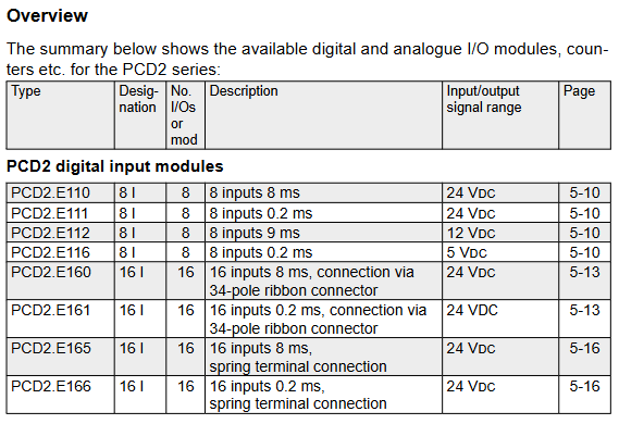
Covering five major categories of modules: digital input/output modules, analog input/output modules, digital hybrid I/O modules, counting and motion control modules, and special function modules (such as weighing and thermocouple modules), while distinguishing the differences between PCD2 and PCD3 series modules (such as the addition of cage spring terminals and higher anti-interference levels in PCD3), supporting industrial standard signal types such as 24V DC/115-230V AC input and 0-10V/0-20mA analog signals. Some modules have electrical isolation (up to 500V isolation voltage) and short-circuit protection functions.
Version and compatibility
Document historical version updates focus on module function supplementation (such as adding PCDx.B160/W380/G200 modules in ENG07), parameter correction (such as adjusting product status section in ENG09), and the latest version of ENG10 optimizes PCD3.A810/W800 power consumption parameters; In terms of hardware compatibility, the PCD2 module needs to be compatible with CPU hardware version H or above, while the PCD3 module supports RIO remote IO systems (some modules such as H210/H31x are currently not compatible).
Core module classification and technical parameters
(1) Core parameters of PCD2 series modules
1. Digital input module
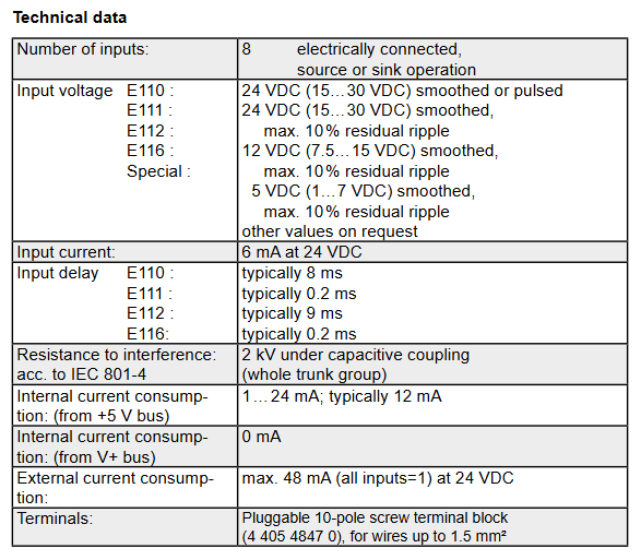
Module model, number of input channels, signal range, response time, electrical isolation, wiring method
PCD2.E110 8 24V DC 8ms without 10 pole screw terminal
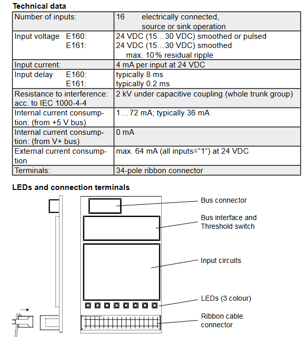
PCD2.E160 16 24V DC 8ms without 34 pole ribbon cable connector
PCD2.E500 6 115-230V AC 10ms (pull in)/20ms (release) with (2.5kV optocoupler isolation) 10 pole screw terminal
PCD2.E610 8 24V DC 10ms with (1kV AC isolated) 10 pole screw terminal
2. Digital output module
Module model, output channels, rated current signal range, protection function
PCD2A300 6 2A/channel 10-32V DC without short circuit protection, requires external 12.5A fast melting
PCD2.A400 8 0.5A/channel 5-32V DC without short circuit protection, load resistance ≥ 48 Ω
PCD2.A200 4 2A/channel (relay) 250V AC/50V DC varistor+RC component contact protection
PCD2.A410 8 0.5A/channel 5-32V DC electrical isolation (1kV AC), without short circuit protection
3. Analog input module
Module model, channel number, resolution, signal type, accuracy (25 ℃)
PCD2.W100 4 12 bit 0-10V/-10~+10V ± 0.1% ± 1LSB
PCD2.W220 8 10 bit Pt/Ni1000 temperature sensor ± 3LSB
PCD2.W305 7 12 bit 0-10V ± 0.15%
PCD2.W745 4 16 bit J/K type thermocouple ± 0.4 ℃ (0-100 ℃)
4. Counting and motion control module
Module model, function, highest frequency, number of axes, encoder support
PCD2.H100 pulse counting 20kHz incremental encoder (phase A/B)
PCD2.H150 SSI interface 500kHz 1 absolute encoder (SSI protocol)
PCD2.H210 stepper motor control 19.45kHz 1 24V DC encoder
PCD2.H310 servo motor control 100kHz 1 24V DC incremental encoder
(2) Core Upgrade of PCD3 Series Modules
The PCD3 series optimizes terminal design, anti-interference performance, and functional expansion based on PCD2, with the following core differences:
Module type: PCD2 series features: PCD3 series upgrade points
The screw terminal of the digital input module (with a maximum wire diameter of 1.5mm ²) has added cage spring terminals (such as 24 pole terminals for E165, supporting a wire diameter of 1.0mm ²), and the anti-interference level has been raised to IEC 61000-4-4 (± 2kV capacitive coupling)
The 8-bit resolution of the analog output module is mainly increased from the W6x0 series to 12 bit resolution, with an output delay of ≤ 10 μ s and support for -10~+10V bipolar signals
The motion control module only supports local IO H32x series, supports DSP processors, realizes S-curve trajectory planning, and supports 250kHz encoder input
Wiring compatibility only supports fixed terminals, supports PCD3.K010/K106 connection cables, and modules can be directly cascaded (maximum distance of 2.5m)
(3) Electrical isolation and safety characteristics
Isolation type and level
Digital isolation module (such as PCD2. E610/PCD3. E610): using optocoupler isolation, isolation voltage 1000V AC (1 minute), no isolation between channels, suitable for strong interference environments (such as near frequency converters);
Analog isolation module (such as PCD2. W3x5/PCD3. W3x5): adopts DC/DC isolation, isolation voltage of 500V, supports 7-channel analog signal acquisition, suitable for signal isolation in process control (such as chemical equipment).
Safety Specifications
High voltage modules (such as PCD2, E500, PCD3, E500115-230V AC input) need to be separately equipped with fuses (1A/250V), and are prohibited from being connected together with low voltage signals (≤ 50V);
The contact protection of relay output modules (such as A200/A210) needs to be matched with the load type: inductive loads require external current diodes, and capacitive loads require series current limiting resistors to avoid contact arc damage.
Installation and wiring specifications
(1) Mechanical installation requirements
Installation environment
Working temperature: 0-55 ℃ (if it exceeds 40 ℃, the output current should be reduced by 2% for every 1 ℃ increase);
Protection level: IP20 (IEC 60529), to be installed inside the control cabinet to avoid dust and condensation water;
Installation spacing: Reserve ≥ 25mm heat dissipation space on both sides of the module for vertical installation (allowing ± 15 ° tilt), and additional fixation is required for heavy-duty modules (such as PCD2. H32x).
Terminal installation
Screw terminal: torque 0.7-0.8Nm (compatible with M3 screws), wire diameter 0.5-2.5mm ²;
Cage type spring terminal (PCD3 specific): No tools required, directly insert the wire (maximum 1.0mm ²), press the release button when pulling out, and increase wiring efficiency by 30%.
(2) Key specifications for electrical wiring
Power supply and grounding
Digital module: 24V DC power supply needs to be supplied separately (ripple ≤ 10%), PE wire cross-section ≥ 1.5mm ², single point grounding is used (grounding resistance ≤ 1 Ω);
Simulation module: The signal ground and power ground are wired separately, and the analog signal cable adopts twisted pair shielded wire (single end grounding of the shielding layer) to avoid parallel connection with the power cable (spacing ≥ 200mm).
Typical wiring example
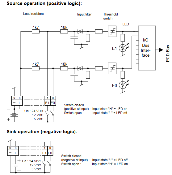
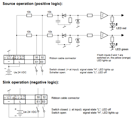
Digital input (source wiring): PCD2.E110 module E0-E7 is connected to the sensor signal,+24V is connected to the positive pole of the external power supply, and the negative pole of the sensor is connected to the module GND. The LED lights up to indicate that the input is valid;
Analog output (current type): PCD3.W410 module A0 connected to actuator (such as valve positioner), external 24V DC power supply positive pole connected to actuator, negative pole connected to module A0 terminal, select 4-20mA signal range through jumper;
Isolation module: The PCD2.E610 module needs to be separately connected to a 24V isolation power supply, and the signal end should be completely isolated from the PLC system ground to avoid common ground interference.
Function configuration and programming support
(1) Hardware configuration
Address setting
Digital module: Set the CANopen station address (1-99) and baud rate (10-1000kbit/s) through the DIP switch on the front-end of the module. After setting, restart the 24V power supply to take effect;
Expansion card configuration: Multifunctional modules such as PCD2.G410 need to be plugged into a communication expansion card (such as a PROFIBUS card) through Slot 1/2, and the module will automatically recognize it after power on. If it is not recognized, the locking status of the card buckle needs to be checked.
Signal filtering
Digital input: Select the filtering time through the internal jumper of the module (such as PCD2.E111 supporting 0.2ms/8ms switching), and select a short filtering time for high-frequency signals (such as encoders);
Analog input: PCD3.W380 supports software configuration of digital filtering (50/60Hz notch filtering) to suppress power grid interference, with a filtering time constant of 2.4ms.
(2) Software Configuration (PG5 Environment)
tool support
Saia PG5 software (version ≥ 2.3) is required to configure module parameters through the "Device Configurator":
Motor configuration: Select the motor model (such as AKM series servo motor), automatically load rated current, inductance and other parameters, and execute "Motor Probe" to optimize the current loop gain;
Safety configuration: The STO function needs to be associated with a safety controller and set a periodic testing interval (≤ 8 hours, meeting SIL CL3 requirements);
Linearization of analog signals: The PCD2-W745 thermocouple module requires the selection of thermocouple type (J/K type), and the software automatically compensates for the cold junction temperature (compensation accuracy ± 0.2 ℃).
Programming Example
Counting function: PCD2.H100 reads the counting value through the IL command "RD-DIGIAL-IO-0TO15", and sets "WR-DIGIAL-OUTPUT0TO15" to trigger the counter reset;
Servo control: PCD2.H310 sets the target position through the FB function block "MC_SoveAbsolute", and the parameter "Position" is filled in with the number of pulses (to match the electronic gear ratio).
Troubleshooting and Maintenance
(1) Common faults and solutions
Troubleshooting steps for possible causes of fault phenomena
No response to digital input (LED not lit) 1. Power supply not working; 2. Loose wiring; 3. Input signal exceeds the range. 1. Measure the 24V voltage at the X4A terminal of the measurement module; 2. Re tighten the terminal screws (torque 0.8Nm); 3. Check the sensor output (e.g. NPN sensor needs to output a low level)
Simulated output deviation exceeds tolerance 1. Calibration parameters are lost; 2. Load impedance mismatch; 3. Signal distortion caused by interference. 1. Perform "Analog Calibration" through PG5 to recalibrate; 2. Confirm load resistance: voltage output ≥ 3k Ω, current output ≤ 500 Ω; 3. Add shielding layer grounding (single ended grounding)
Relay output contact adhesion: 1. Load current exceeds the set value; 2. Contactless protective components; 3. Frequent switching: 1. Measure the load current (such as A200 maximum 2A/channel); 2. Inductive load connected in parallel with 1N4007 freewheeling diode; 3. Reduce switching frequency (recommended ≤ 10 times/minute)
The frequency of the counting module is abnormal. 1. The encoder cable is too long; 2. Signal interference; 3. Improper setting of filtering time: 1. Cable length ≤ 10m (signal repeater is required for over distance); 2. Use twisted pair shielded wires (with the shielding layer grounded); 3. Set the filtering time to 1/5 of the signal period (e.g. 10 μ s for a 20kHz signal)
(2) Regular maintenance project
Standard requirements for maintenance project cycle operation content
Terminal inspection every quarter: 1. Tighten screw terminals (torque 0.7-0.8Nm); 2. Clean the terminal dust and ensure that the terminal is free from oxidation and looseness, with a contact resistance of ≤ 10m Ω
Module temperature monitoring: 1. Measure the temperature of the heat sink every month; 2. Check the fan speed (e.g. PCD2.H32x fan ≥ 2500rpm), the temperature of the heat sink is ≤ 75 ℃, and the fan has no abnormal noise
Calibration verification every six months: 1. Analog input: Input standard signal (such as 5V/10mA), read module values; 2. Analog output: Set 50% output, measure actual value deviation ≤ ± 0.5% (if exceeded, recalibration is required)
Monthly safety function testing: 1. Trigger the STO function and check if the motor torque is cut off; 2. After testing the safety relay contacts and activating STO, the motor has no torque, and the contact response is ≤ 10ms
Product lifecycle and spare parts management
Product status classification
The manual specifies the status of modules "Active", "Outphased", and "Repair phase":
The maintenance period for discontinued modules (such as PCD2.G400/G410) is until December 31, 2018, and there will be no spare parts supply thereafter;
Alternative solutions: Replace PCD2.W100 with PCD2.W380, and PCD2.H222 with PCD3.H222.
Recommended spare parts list
It is recommended to reserve 1-2 sets of key spare parts, with the following matching models:
Module type/common model/spare part model
Digital input module/PCD3.E110/PCD3.E111 (compatible and responsive)
Analog output module/PCD2.W410/PCD3.W410 (terminal upgrade)
Relay module/PCD2.A200/PCD3.A200 (same function, higher anti-interference)
Counting module/PCD2.H100/PCD3.H110 (maximum frequency increased to 100kHz)
- YOKOGAWA
- Reliance
- ADVANCED
- SEW
- ProSoft
- WATLOW
- Kongsberg
- FANUC
- VSD
- DCS
- PLC
- man-machine
- Covid-19
- Energy and Gender
- Energy Access
- Renewable Integration
- Energy Subsidies
- Energy and Water
- Net zero emission
- Energy Security
- Critical Minerals
- A-B
- petroleum
- Mine scale
- Sewage treatment
- cement
- architecture
- Industrial information
- New energy
- Automobile market
- electricity
- Construction site
- HIMA
- ABB
- Rockwell
- Schneider Modicon
- Siemens
- xYCOM
- Yaskawa
- Woodward
- BOSCH Rexroth
- MOOG
- General Electric
- American NI
- Rolls-Royce
- CTI
- Honeywell
- EMERSON
- MAN
- GE
- TRICONEX
- Control Wave
- ALSTOM
- AMAT
- STUDER
- KONGSBERG
- MOTOROLA
- DANAHER MOTION
- Bentley
- Galil
- EATON
- MOLEX
- Triconex
- DEIF
- B&W
- ZYGO
- Aerotech
- DANFOSS
- KOLLMORGEN
- Beijer
- Endress+Hauser
- schneider
- Foxboro
- KB
- REXROTH
- YAMAHA
- Johnson
- Westinghouse
- WAGO
- TOSHIBA
- TEKTRONIX
- BENDER
- BMCM
- SMC
- HITACHI
- HIRSCHMANN
- XP POWER
- Baldor
- Meggitt
- SHINKAWA
- Other Brands
- UniOP
- KUKA
- IBA
- Beckhoff
-
Woodward 8272-796 - Real Power Sensor Module 115/230v-ac
-
Woodward 5463-873 - NetCon Output Module
-
Woodward 8271-567 - Load Sensor Module 120/208v-ac
-
Woodward Type UG-8 P/N 8522-300 EG - Governor R.P.M 1075-1650 With Motor Groschopp
-
WOODWARD 9905-971 REV J - LINKNET 16 CHANNEL DISCRETE INPUT MODULE
-
WOODWARD 8280-3014 - 723 PLUS DIGITAL CONTROL REV NEW
-
Woodward 505DE - Digital Control System
-
Woodward 5453-750 - Ethernet Interface FTM
-
Woodward 9907-018 Rev H - 2301A Load Sharing & Speed Control
-
WOODWARD 5420-1080 V4.3 - BOARD-PPA WITHBOX
-
Woodward b 8271-347SP - 2301 speed control
-
Woodward 9905-795 Rev B - Digital Synchronizer and Load Control
-
Woodward 9905-377 Rev. A - 2301A Load Sharing and Speed Control
-
WOODWARD 8272-582 - Generator speed control module
-
WOODWARD 9907-247 REV K - 828 DIGITAL CONTROL UNIT
-
WOODWARD 5466-353 REV C - NETCON MAIN CHASSIS TRANSCEIVER
-
Woodward Type UG-8 P/N 8524-708 - Governor 760-1560 Governor R.P.M
-
WOODWARD 9907-247 REV K - 828 DIGITAL CONTROL UNIT
-
WOODWARD 8440-1831 REV. H - EASYGEN3000 3200-5 - WITHOUT ACCESSORIES
-
WOODWARD 8444-1002 REV G - UMT1 MEASURING TRANSDUCERS
-
Woodward 5410-312C - Digital Marine Control Printed Circuit Board
-
Woodward 9905-799 REV F - Digital Synchronizer & Load Control , V#456
-
Woodward 9907-014 - 2301A for controller
-
Woodward Type UG-8 P/N B522-446 - Governor R.P.M 500-1200
-
WOODWARD 8272-221 REV.B - DIGITAL REFERENCE UNIT
-
Woodward 8901-037 - Booster Servomotor Single
-
WOODWARD 8444-1019 REV G - UMT 1 MEASURING TRANSDUCER
-
WOODWARD 1767-367 Z21 WK 0920702 - GOVERNOR MOTOR 2700 RPM KM 58-20 K 230V
-
WOODWARD 9905-972 Rev:G - LINKNET 6 CHANNEL 4-20mA OutPut
-
Woodward E8250-501 - Actuator Governor
-
WOODWARD 5466-258 REV M - SIMPLEX DISCRETE I/O MODULE
-
WOODWARD 5501-470 REV E - NETCON CPU MODULE
-
Woodward 8406-120 rev H - egcp-2 digital control
-
Woodward 8440-1799 - Easygen-350 Rev B
-
Woodward 8440-1878 - DSLC-2 Digital Synchronizer Load Control
-
Woodward 5464-843 - Cpu Processor Module
-
WOODWARD 8440-1409 Rev. J - MFR2 MDE Synchronization & Protection MSP
-
Woodward 9907-014 - controller
-
WOODWARD 9907-173 - LOAD SHARING MODULE 120V
-
WOODWARD 8440-1831 REV. K - EASYGEN 3200-5 - WITHOUT ACCESSORIES
-
Woodward 9905-969 - LinkNet Module LinkNet 6C 4-20ma in w/24v
-
Woodward 8520-498 - Governor Type UG-8 Governor R.P.M 850-1650
-
WOODWARD 5466-257 REV.-C - NETCON 5000 MODEL REMOTE TRANSCEIVER I/O MODULE
-
WOODWARD 8800 - 1001 REV-C - DSS-2, 2 CHANNEL DIGITAL SPEED SWITCH
-
WOODWARD 5501-467 REV. C - MICRONET SIMPLEX POWER SUPPLY
-
Woodward 8273-584 - Atlas-ii Digital Control
-
Woodward 8440-1019 b - spm-d10 synchronizing system
-
Woodward CSC3SUWA REV K - CSC3SUWA Controller
-
Woodward 5441-693 Rev B - Digital I/O Module
-
WOODWARD DPG-2201-002 REV.D - Governor Onan DIGITAL SPEED CONTROLLER
-
Woodward 9905-377 Rev. A - 2301A Load Sharing and Speed Control
-
WOODWARD 8440-1884K - GENERATOR CONTROLLER EASYGEN-2500-5 REV,K
-
WOODWARD 8404-1006 - Industrial Component
-
WOODWARD 5437-1118 - PROTECHTPS MODULE Relay Bulkhead Panel
-
Woodward 8440 1801 Rev C - Easygen-350-50B/X Genset Control Engine Generator 24VDC
-
WOODWARD 5466-348 - MODULE
-
Woodward 9905-799 REV F - Digital Synchronizer & Load Control , V#456
-
Woodward 9907-018 - 2301A Load Sharing & Speed Control Rev H
-
Woodward GM9412H918-R2 1766-039 REV E - Cruise Control Motor
-
5466-258 WoodWard - 48 Input 24 Output Discrete I/O, (UPP)
-
WOODWARD 5484-877 - PM MOTOR 24VDC 15RPM
-
Woodward 8272-221 B - Digital Reference Unit
-
Woodward 9905-796 - Digital Synchronizer And Load Control (Rev. H)
-
WOODWARD 5441-645 REV.G - 10AMP RELAY INTERFACE 11459968
-
Woodward 9907-207 - 721 Digital Control 88-132VAC
-
WOODWARD 8272-582 - APM MOTOR CONTROL AC/DC 100~220V
-
Woodward 5464-843 - Cpu Processor Module
-
Woodward 9905-001 L - SPM-A Synchronizer 115/230V 50/60Hz 10W
-
Seg Power Protection PCK4 P/N 8445 1006 A / PCKR-MW - Protection Relay 24VDC
-
Woodward 8405-062 - Actuator
-
Woodward 5464-738 - Industrial Control System
-
Woodward CSC3HUWB - controller
-
Woodward 8272-517 - PM Motor Control 220vac
-
Woodward 8272-582 - APM Motor Control
-
Woodward LR20025 MFR1375M MFR 1 - Controlling
-
Woodward 9905-392 - Proact Driver Model III
-
WOODWARD 8250-774 - ACTUATOR/GOVERNOR
-
Woodward 505DE - Digital Control System
-
Woodward 8280-303 D - 721 Digital Control Rev.G 2.0 AMP 28 VDC
-
WOODWARD DPG-2201-002 REV NEW - DIGITAL CONTROLLER
-
WOODWARD 8272-286 - 2301A LOAD SHARING & SPEED CONTROL MODULE
-
WOODWARD 8440-1884 REV M - GENSET CONTROLLER EASYGEN-2500-5/P1
-
Woodward 9905-797 Rev. M - Digital Sync And Charge Control
-
W0ODWARD ART-01681 - IDS Communicator Control Box
-
Woodward 8273-584 - Digital Control Unit ATLAS-II REV: A 18-32VDC, 60W
-
WOODWARD 5501-470 REV E - NETCON CPU MODULE
-
Woodward 1752 1752-227 - Revision D FireFly Current Load input Engine Control
-
Woodward 8440-1877 - MSLC-2-5 Control
-
Woodward 8271468 - Generator Loading Control (Rev. D)
-
Woodward 9905-387 - Pro Act Driver Model lll (Rev. F)
-
Woodward 9905-363 - Sincronizzatore Digitale E Controllo Carico
-
WOODWARD 8272-583 - APM MOTOR CONTROL
-
WOODWARD EGCP-2 - Digital Generator Control Panel 4-20MA 5V 500HZ
-
Woodward 9905-392 - Proact Driver Model III
-
Woodward 9905-392 - Proact Driver Model III
-
Woodward 8270-007 - Load Signal Control
-
Woodward 8271-651 - Digital Speed Reference
-
WOODWARD 8440-2219 - EASYGEN-2500-5-P1-K49 GENSET CONTROLLER
-
Woodward D8271-394 - 2301 Load Sharing And Speed Control Module 20-40v-dc
-
Woodward 8200-1504 Rev:E - Peak200 Steam Turbine Control Front Panel Mount HVAC
-
WOODWARD 8444-1022 REV F - UMT 1 MEASURING TRANSDUCER
-
WOODWARD 8440-1923 A - EASYGEN-3200-5 CONTROLLER
-
WOODWARD 9907-014 - 2301A controller
-
Woodward 8272-583 - Amp Motor Control DC24V
-
Woodward 9907-147 REV N - ProTech 203 Overspeed Protection System
-
Woodward 8270-417 - 2301 speed sensor
-
Woodward 8272-583 - Amp Motor Control DC24V
-
Woodward 8934-658 - Repair Kit UG8D Governor
-
Woodward 5437-281 - analog module
-
Woodward 8440-2177 A - SPM-D2-10 Digital Synchronising Controller
-
SA-4478 EPS1000 - Speed Switch
-
Woodward 9907-014 Rev: J - 2301A Speed Control
-
Woodward 9907-026 Rev C - Load Sharing Module
-
Woodward B8271-464 H B8271464 - 2301 Speed Control
-
WOODWARD 8440-1667 REV C - SPM-D10 SYNCRONIZING UNIT
-
Woodward 8440-2082 - EASYGEN-3200XT-P1 Engine Generator Control
-
Woodward 8406-120 rev H - egcp-2 digital control
-
WOODWARD SPM-D - SYNCHRONIZING SYSTEM
-
Woodward 8271-651 - Digital Speed Reference
-
WOODWARD 8444-1074 A - MODULE
-
WOODWARD 8440-2050 Rev B - EASYGEN-3200-5 CONTROLLER
-
Woodward 8440-1613 REV E - GCP30 Genset Control Package
-
Woodward 9907-018 - Load Sharing & Speed Controller Rev H 90-240VAC
-
Woodward 5466-315 - module
-
Woodward 9905-204 Rev N - SPM-A synchronizer
-
Woodward XG2 - Protection relay
-
WOODWARD 9907-175 LOAD SHARING MODULE REV A - Load Sharing Module
-
Woodward 9907-166 REV: N - 505E Turbine Control 110V AC/DC

K-JIANG

Add: Jimei North Road, Jimei District, Xiamen, Fujian, China
Tell:+86-15305925923