
K-WANG


SCHNEIDER Back-UPS ™ Pro 550/900/1200/1500 230V Installation and Operation
SCHNEIDER Back-UPS ™ Pro 550/900/1200/1500 230V Installation and Operation
The installation and operation manual for APC by Schneider Electric Back UPS Pro 550/900/1200/1500 230V series UPS covers five core modules: safety specifications, hardware connections, functional configuration, fault diagnosis, and after-sales service. It specifies that the UPS needs to be used indoors and supports core functions such as battery backup (the longest endurance depends on the model), surge protection, and automatic voltage regulation. Power saving, sensitivity, and other parameters can be configured through the front panel button or PowerChute software. The battery life is usually 3-5 years. In case of a fault, the problem can be located through the fault code, and official after-sales maintenance should be contacted. Different models correspond to specific replacement batteries (such as BR550GI corresponding to APCRBC110)
Safety and Installation Standards
(1) Safety requirements
Usage environment: For indoor use only, avoid direct sunlight exposure, contact with liquids, excessive dust, or environments with excessive humidity.
Power connection: The UPS power cord should be directly plugged into a wall socket, and the use of surge protectors or extension cords is prohibited.
Heat dissipation requirements: The ventilation openings must not be obstructed, and sufficient space should be reserved to ensure normal heat dissipation.
Battery Attention: The battery life is usually 3-5 years. High ambient temperatures, poor power quality, and frequent short-term discharges can shorten the lifespan.
(2) Hardware connection
Connection type operation instructions applicable to devices
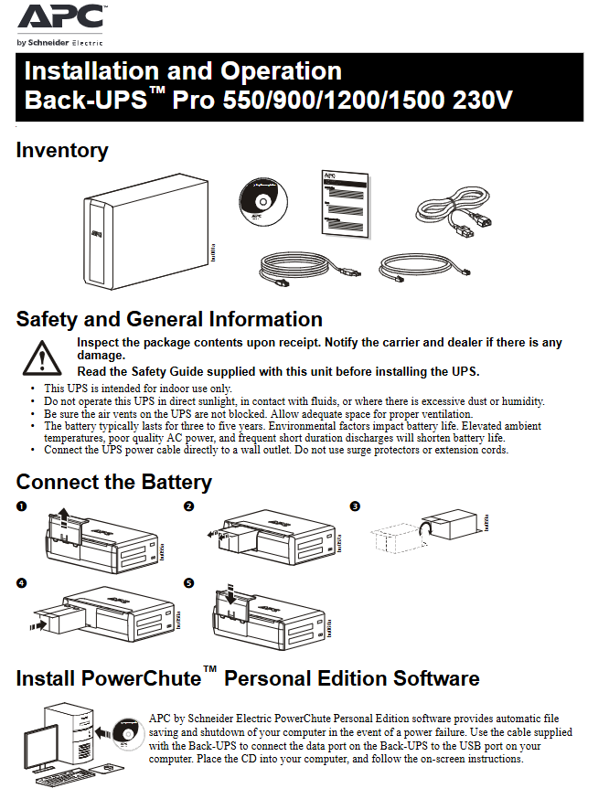
Battery connection: Follow the manual instructions to complete the installation of the built-in battery (some models are pre installed at the factory) for all models
Connect critical devices (computers, monitors, modems) to "Battery Backup outlets", and non critical devices (printers, scanners) to "Surge Protected outlets" for all models
Connect the data port of UPS to the USB/serial port of the computer using the matching cable for data connection, and install PowerChute software (to achieve automatic file storage and shutdown) for all models
Expand the connection of the telephone line to the "Telephone In" port, and connect the modem to the "Telephone Out" port; Ethernet cable connected to "Ethernet In", computer connected to "Ethernet Out" (only supports 10/100/1000BASE-T) for some models (such as BR550GI/900G-FR)
Ground Screw "BR1200GI/1500GI, BR1200G-FR/1500G-FR for additional surge suppression equipment grounding connection
External battery connection BR1500GI/1500G-FR extends battery life by connecting the external battery pack through the "External Battery Pack connector"
Core functions and configurations
(1) Power saving function
Enable/Disable: Long press the "MUTE" and "PLAY" buttons on the front panel for 2 seconds, the UPS beeps and the "leaf icon" on the display screen lights up/goes out to indicate whether the function is enabled/disabled.
Threshold calibration: When the main device (such as a computer) is in sleep/shutdown mode, long press "MUTE" and "PLAY" for 6 seconds, the leaf icon will flash 3 times and beep 3 times to complete threshold saving (adapted to different device sleep power consumption).
(2) Display mode configuration
Mode Type Operation Method Function Description
Long press and hold "PLAY" for 2 seconds in constant light mode, and the display screen will continue to light up with a beep confirmation
Power saving mode: Long press and hold "PLAY" for 2 seconds without any operation. After 60 seconds, the display screen will darken. Press any button to restore brightness
(3) Sensitivity adjustment
Operation steps: 1 UPS connected to AC power but turned off; 2. Long press "POWER" for 6 seconds, and the "LOAD CAPACITY" indicator light will flash to enter programming mode; 3. Press "POWER" to switch between low/medium/high sensitivity and beep to confirm.
Sensitivity Description: Low sensitivity (switching battery when input voltage is extremely low, not recommended for computer loads), medium sensitivity (default, suitable for most devices), high sensitivity (suitable for voltage fluctuation sensitive devices, frequent battery switching).
(4) Other key operations
Notes on Function Operation Methods
Manual self-test: Press and hold "POWER" for 6 seconds to automatically perform a self-test when the device is turned on
Silent alarm. Short press "MUTE" to only turn off the alarm triggered by the current event
When clearing the event count display event interface, long press "PLAY"+short press "POWER" to clear only the AC fault counter
Fault reset: Long press "POWER" for 2 seconds to clear the visual prompt of the fault and restore standby mode
Status indication and troubleshooting
(1) Sound warning and status icon
Suggestions for handling the corresponding status of sound prompts
Every 30 seconds, there are 4 battery powered sounds to save the current work progress
Continuous buzzing, low battery, immediately save work, close applications and operating systems
Continuous beeping, battery backup output overload, disconnection of non essential equipment
Every 5 hours, beep for 1 minute. Battery diagnosis fails. Replace battery
Suggestions for handling the meaning of status icons
Overload (flashing) When AC power is supplied, overload and disconnect non essential equipment until the icon goes out
Overload (always on) When the battery is powered on, unload the device immediately to avoid battery damage
Replace Battery Failure/End of Life Replace the corresponding model battery
On Battery: The battery is supplying power. Please restore AC power or save data as soon as possible
(2) System fault code
Fault code, fault type, and handling method
F01 battery power overload shutdown → disconnect non essential equipment → restart UPS
F02 battery output short circuit shutdown → Disconnect all devices → Reconnect one by one to locate the faulty device
F03-F09 capacitor overload/clamp short circuit/charging fault cannot be handled by oneself, contact official technical support
(3) Common problem troubleshooting
Possible causes and solutions for the problem phenomenon
UPS cannot start up, AC power not connected/circuit breaker tripped/battery not connected. Check power connection → reset circuit breaker → confirm battery installation
After a power outage, if there is no backup power supply device, connect it to the wrong socket (plugged into the surge protection port) and move the critical equipment to the battery backup socket
Backup battery life shorter than expected, non essential devices occupying battery load/battery not fully charged, unloading non critical devices → charging for 16 hours → checking battery status
Some sockets have no power supply and the power saving function is enabled. The controlled sockets have been turned off and the power saving function is disabled or the threshold is recalibrated
The battery replacement indicator light is on. When the battery life expires, replace the backup battery of the corresponding model (such as APCRBC124 for BR1500GI)
Product specifications
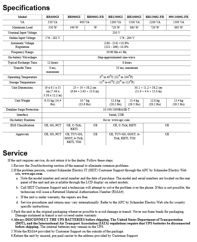
Model Capacity (VA) Maximum Load (W) Input Voltage Range (V) Typical Charging Time (hours) Conversion Time (maximum)
BR550GI 550 330 176-282 12 8 ms
BR900GI 900 540 176-294 8 10 ms
BR1200GI 1200 720 176-294 8 10 ms
BR1500GI 1500 865 176-294 8 10 ms
BR900G-FR 900 540 176-294 8 10 ms
BR1200G-FR 1200 720 176-294 8 10 ms
BR1500G-FR 1500 865 176-294 8 10 ms
- YOKOGAWA
- Reliance
- ADVANCED
- SEW
- ProSoft
- WATLOW
- Kongsberg
- FANUC
- VSD
- DCS
- PLC
- man-machine
- Covid-19
- Energy and Gender
- Energy Access
- Renewable Integration
- Energy Subsidies
- Energy and Water
- Net zero emission
- Energy Security
- Critical Minerals
- A-B
- petroleum
- Mine scale
- Sewage treatment
- cement
- architecture
- Industrial information
- New energy
- Automobile market
- electricity
- Construction site
- HIMA
- ABB
- Rockwell
- Schneider Modicon
- Siemens
- xYCOM
- Yaskawa
- Woodward
- BOSCH Rexroth
- MOOG
- General Electric
- American NI
- Rolls-Royce
- CTI
- Honeywell
- EMERSON
- MAN
- GE
- TRICONEX
- Control Wave
- ALSTOM
- AMAT
- STUDER
- KONGSBERG
- MOTOROLA
- DANAHER MOTION
- Bentley
- Galil
- EATON
- MOLEX
- Triconex
- DEIF
- B&W
- ZYGO
- Aerotech
- DANFOSS
- KOLLMORGEN
- Beijer
- Endress+Hauser
- schneider
- Foxboro
- KB
- REXROTH
- YAMAHA
- Johnson
- Westinghouse
- WAGO
- TOSHIBA
- TEKTRONIX
- BENDER
- BMCM
- SMC
- HITACHI
- HIRSCHMANN
- XP POWER
- Baldor
- Meggitt
- SHINKAWA
- Other Brands
- UniOP
- KUKA
- IBA
- Beckhoff
-
LTI SC52.0040.0012.0000.0 - Servo Drive
-
Lti SC52.0040.0012.0000.0 - Servo Drive
-
Milton Industries LTI Tool By Milton LT1240 - 1/2" Drive Lugnut Remover
-
LTi Drives SO84.200.P030.0000.0-W - Servo Spindle Drive
-
LTI DRIVES LSP08-035-320-30-B0R1PY170 - Servo Motor
-
LTI DRIVES SE84.200.SC00.0001.0-W - Servo Drive
-
Lust CDE34.005.W2.2 - Lti Drives Controller
-
LTi SO84.012.0030.0011.2 - ServoOne Servo Drive
-
LTi Drives SO CM-P.0010.11.00.0 - Servo Drive Controller
-
LTi CDE34.017.W3.0 - Servo Drive
-
LTI Drives CDB32.004, C2.0,SH - Positioning Controller
-
LUST CM-CAN1 - LTi DRIVES Communication Module
-
LTi SO84.012.1030.0000.2 - Servo Drive
-
LTI MOOG CDE54.044 - PITCHMASTER FREQUENCY CONVERTER 181-01019
-
MOOG LTI 181-01019 CDE54.044 - PITCHMASTER FREQUENCY CONVERTER
-
Lust LTi Drives CDE34.010,D2.0 - Servo Drive Controller
-
LTI SO84.032.0003.0101.2 - Servo Drive
-
Seagate 9CC132-302 Harris LTI-CS IRT-34-0021-01 - Hard Drive 160GB
-
LTI SO84.032.0003.0001.2 - Servo Drive
-
LTI SO24.007.0070.0000.1 - SERVO CONTROLLER
-
LTi drive CDA32.003.C3.0.H05-01.PC1 - Servo Drive
-
LTI SO84.016.0030.0000.2 - SERVO CONTROLLER
-
LUST LTI CD A34.008,W1.4, BR - SERVO DRIVE
-
MOOG LTI 181-01019 CDE54.044 - PITCHMASTER FREQUENCY CONVERTER
-
LTI MOOG 181-01019 - PITCH Master Servo Drive CDE54.044
-
LTI SERVO ONE SO84.045.0030.0001.2-W - Drive
-
LUST LTi SO84.032.0040.0000.2 - SERVO ONE DRIVE
-
LTi Drives LSH-074-2-30-3 20/T1,G6.1M - SERVO MOTOR
-
LTI SO84.016.0000.0101.2 - servo drive
-
LTI SA54.0550.0033.0000.0 - Servo Drive
-
LTI SA54.0550.0033.0000.0 - Servo Drive
-
LTI LT 4850 - 3/8" Drive 3-Pc Twist Socket Transmission Drain Plug Removal System
-
LTI Tools LT4400-30 Lock Technology - 3/4" Twist Socket 1/2" Drive Lugnut Remover
-
LTI Tools LT-1400C - 1/2 Drive Wheel Torque Extension Tool
-
LTI Tools LT1250 - 1/2" Drive Dual Sided Socket Lug Nut Remover Tool
-
LTI SO84.032.0003.0101.2 - Servo Drive
-
LTI MOOG 181-01019 - PITCH Master Servo Drive CDE54.044
-
MOOG LTI 181-01019 CDE54.044 - PITCHMASTER FREQUENCY CONVERTER
-
MOOG LTI 181-01019 CDE54.044 - PITCHMASTER FREQUENCY CONVERTER
-
MOOG LTI 181-01019 CDE54.044 - PITCHMASTER FREQUENCY CONVERTER
-
LTI SA54.0550.0033.0000.0 - Servo Drive
-
LTI Tools LT-4800 - 7 Piece Twist Socket 3/8" Drive Oil Drain Plug Removal Set
-
LTI SA54.0550.0033.0000.0 - Servo Drive
-
LTI Drive SO24.007.00300000.0 - Servo Drive
-
LTI TOOLS LTI 1400-I - Drive Wheel Torque Extension
-
LTI Tools LT4400-3 - 3/4" 19mm Twist Socket 1/2" Drive Lugnut
-
LTI TOOLS LTI 1400-BB - Drive Wheel Torque Extension
-
LTI SO84.032.0003.0101.2 - Servo Drive
-
LTI Tools LT-4512 - 3/8" Drive 12mm Twist Socket
-
LTI MOTION Luster SO84.032.0003.0001.2 - Servo Drive
-
LTI Tool By Milton LT1600P - 1" Drive Torx Stick
-
LTI Lust VF1424L,HF,OP2,S56 - Variable Frequency Drive
-
LUST CDA32.004,C1.4,H08,B0 - SERVO DFRIVE CM-CAN1 Module
-
LTI SO84.045.0002.0001.2-W - Drive
-
LTI Lust VF1404M,C9,PT1,BR1 - Inverter Type VF1404M
-
LTI SA54.0550.0033.0000.0 - Servo Drive
-
LTI Tools LT-1400C - 1/2" Drive Wheel Torque Extension
-
Lust LTI DRiVES CDA32.006, C3.0, H09 - Variateur De Fr茅quence Frequency Inverter
-
LTI MOOG CDE54.044 - PITCH master SERVO DRIVE
-
LTI MOOG CDE54.044 - PITCH master SERVO DRIVE
-
LTI SO84.143.0020.0101.2-W - servo drive
-
LTI MOTION SC34.0200.0011.0000.0 - Servo drives
-
LTI SO84.032.0003.0001.2 - Servo Drive
-
LTI DRIVES GmbH MS100 - Assembly Set Mounting Kit
-
LTI SO84.032.0003.0001.2 - Servo Drive
-
LTI SO84.032.0003.0001.2 - Servo Drive
-
LTI MOTION SO84.032.0003.0101.2 - servo drive
-
LTI SO84.032.0003.0101.2 - Servo Drive
-
LTI MOOG CDE54.044 - PITCH master SERVO DRIVE
-
LTI MOTION CDE32.004.C2.4 - Servo drives
-
LTI CDD34.032锛學x.x锛孊R锛孭C1 - Servo Drive
-
Lust LTI DRiVES CDA32.006, C3.0, H09 - Inversor De Frecuencia Frequency Inverter
-
Lust SO84.008.0030.1000.0 - Servo One LTi Drive
-
LTI MOTION SO84.032.0003.0101.2 - Servo drives
-
LUST LTi CDA32.004,C1.4 - SERVO DRIVE
-
LTI MOOG CDE54.044 - PITCH Master SERVO DRIVE
-
LTI KEBA CDB32.004 C2.7, SH - PN: 08673530 Frequency Inverter
-
LTI Tools LT-1400C - 1/2" Drive Wheel Torque Extension
-
LTI LT1400-E - 1/2" Drive Wheel Torque Extension
-
LTI MOOG 181-01019 - PITCH master SERVO DRIVE CDE54.044
-
LTI LSN-097-0510-30-560/T1 - Actuator Motor
-
LTI Tools LT 4800 - 7 Piece 3/8" Drive Twist Socket Oil Drain Plug Removal System
-
LTI DRIVES GmbH MS100 - MONTAGESET Assembly Set Mounting Kit
-
Lti SC52.0040.0012.0000.0 - Servo Drive
-
LTI DRIVES GmbH MS100 - Juego De Montaje Assembly Set Mounting Kit
-
LTi DSM4-14.2-21R83-200 - Drives servomoteur Servo Motor
-
MOOG CDE 54.044.GDA - Pitch Master Industrielle Turbine Lti Drive
-
LTI SO24.004.0030.1000.0 - Servo Drive Controller
-
Lti MOOG CDE54.044 - Pitch Master Servo Drive
-
Lust LTI DRiVES CDA32.006, C3.0, H09 - Inverter
-
LTI MOTION GMBH CDB34.006,W3.0,PC1,H39 - Frequency inverter
-
LTI SO84.032.0003.0001.2 - Servo Drive
-
MOOG CDE 54.044.D - Pitch Master Industrielle Turbine Lti Drive
-
LTI TOOLS LT-1460 - 1/2" DRIVE WHEEL TORQUE EXTENSION KIT 5 PIECE SET
-
Lust Cdb32.003, C2.4 - Lti Drives Servoregulador Frecuencia Servo Controller Inverter
-
Lust LTI DRIVES CDA32.006, C3.0, H09 - Frequency Inverter
-
Lust Lti SO82.004.0030.0000.2 - Servo Drive
-
LTI MOTION SC34.0200.0011.0000.0-SL - Servo drives
-
LTI MOTION SA54.0075.0033.0000.0 - Servo drives
-
LTI MOTION SC32.0075.1011.0000.0 - Servo drives
-
LTI Servo-One Junior SO22.006.0080.1000.0 - Servo Controller Servoregler
-
LUST CDA32.004, C1.4, H08, B0 - Servo Drive & LTI CM-CAN1 Module
-
LTI DRIVES LSP08-035-320-30-B0R1PY170 - Servo Motor
-
LUST LTI CDA32.004,C1.4.H08.B0 - SERVO CONTROLLER DRIVES
-
LUST LTi DRiVES CDS44.072LC1.2 - Servo Drive
-
Lti Servo-One Junior SO22.006.0082.1000.0 - Servo Controller Servoregler
-
LUST CDA32.008,C2.0,HF - Lti DRIVES Spindle Drive Inverter
-
LTI SO22.003.0082.0000.0 - Servo Drives One junior Servo Controller Servoregler
-
Lust Lti Drives CM-CAN1 - Communication Module
-
LUST Lti Drives Vf1202s, G8, I6 - Frequency Inverter Drive
-
LTI DRIVES BR-090.03.540.UR.H38 - Bremswiderstand Brake Resistor
-
LTi DRIVES PM-E40.2DRA054P - Wind Turbine Pitch Control Inverter
-
LTi Drives GmbH br-110.01.540-UR - Brake Resistor
-
LTI Drives LSN-097-0960-30-0560/T1,S4,B - Servo Motor
-
LUST CDA34.006.C2.0 - LTI Drives Servoregler
-
LUST LTI DRIVES SERVO ONE JUNIOR SO24.002.0020.0000.1 - Servo Drive Controller
-
LTI MOTION SO84.032.0003.0001.2 - Servo drives
-
LTI DDTD750V2-120 - IBOP ACTUATOR CYLINDER FOR TOP DRIVE
-
LTI CDE32.004, C2.4 - SERVO DRIVE
-
LUST LTI DRIVES CDD34.017 W3.4PC1 - Servo Drive Controller
-
LTI CDA3208,C3,0,HF - AC SERVO DRIVE
-
LUST LTI DRIVES LSH-074-3-30-560/T1,G6.1S - SERVO MOTOR
-
LUST Lti CDB32.004.C2.4.SH - AC Servo Drive
-
LTi CDA32.006, C3.0, H09 - Servo Drive
-
LTI SO22.003.0010.0000.0 - Servo Drive Servo one junior Servoregler Controller
-
LTi Drives DSM4-14.2-21R83-200 - Servo Motor
-
LUST Lti Drives Lsh-097-1-30-560/T1, 1R - Servomotor
-
LTI 1237 - 7 Piece 1/2" Drive Flip Socket Set

K-JIANG

Add: Jimei North Road, Jimei District, Xiamen, Fujian, China
Tell:+86-15305925923