
K-WANG


Siemens SIMATIC ET 200SP Distributed I/O System
Siemens SIMATIC ET 200SP Distributed I/O System
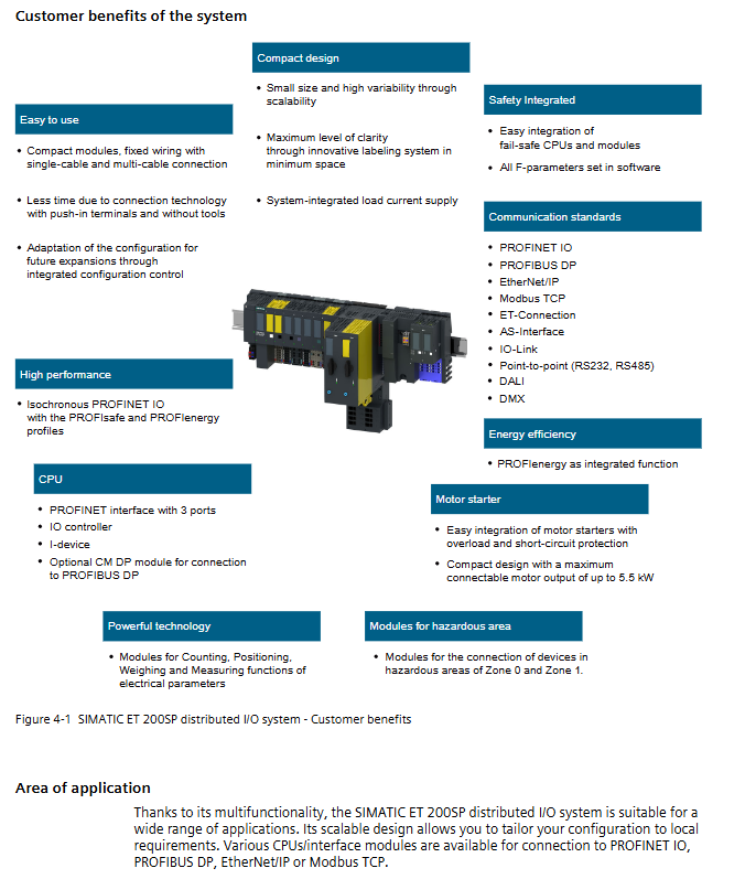
SIMATIC ET 200SP is a scalable and highly flexible distributed I/O system that supports multiple bus protocols such as PROFINET and PROFIBUS. Its core components include CPU/interface modules, I/O modules, motor starters, base units, etc. It has core features such as safety integration, hot plugging, and redundant R1, covering multiple types of modules such as digital/analog/fault safety/explosion-proof, and is suitable for multiple scenarios of industrial automation. It needs to be configured through STEP 7, follows specific installation and wiring specifications, and supports online parameter modification and full lifecycle maintenance.
Overview of System Core
1. System positioning and value
Essence: Distributed I/O system, used to connect process signals with upper level controllers, supporting modular expansion
Core advantages: high flexibility (supporting 1-64 I/O modules), safety integration (fail safe modules), multi scenario adaptation (explosion-proof/redundant/conventional industrial)
Key features: tool free wiring, hot swapping, flexible division of potential groups, multi bus compatibility
2. Core tools and supporting resources
Tool Name Core Function Applicable Scenarios
STEP 7 (TIA Portal) Hardware Configuration, Programming, Parameter Download System Configuration and Debugging
PRONETA PROFINET Network Analysis, Topology Scanning, IO Testing, Network Diagnosis and Debugging
MFCT multi bus configuration, firmware batch update, multi protocol device configuration
SIMATIC Automation Tool for batch debugging, firmware updates, backup recovery, and centralized maintenance across multiple sites
Hardware component details
1. Classification and Parameters of Core Modules
Component type, core model/series, key parameters, functional positioning
CPU 1510SP-1 PN, 1512SP F-1 PN firmware V1.6+, PROFINET 3 port independent control or I-device, supporting fault safety
Interface module IM 155-6 PN HF, IM 155-6 DP HF up to 64 I/O modules, bus protocol adaptation distributed I/O and controller communication bridge
Fault safety module F-DI/F-DQ, F-PM-E SIL3, PL e, Cat.4 safety related signal processing and disconnection
Explosion proof module Ex I/O module, Ex base unit adapted to Zone 0/1 hazardous environment explosion-proof scene signal acquisition and control
Motor Starter DS/RS/F-DS/F-RS 0.1-12A, 5.5kW Maximum Motor Power Motor Start Stop Control and Overload/Short Circuit Protection
2. Key auxiliary components
Base Unit (BU): divided into A0/A1/B0/B1/C0 and other types, adapted to different modules, supporting potential group opening/continuation
PotDis module: 15mm width, supports P1/P2 potential distribution, saves installation space
Server module: Configure the closing component and provide 3 spare fuse installation positions
Bus adapter: Supports PROFINET fiber/Ethernet connections, allowing for free selection of communication media
Core functions and technical parameters
1. Communication and security functions
Communication protocol: Supports PROFINET IO (real-time synchronization), PROFIBUS DP (long-distance transmission), Modbus TCP/EtherNet/IP, etc., to meet different networking requirements
Safety performance: The fault safety module supports SIL2/SIL3 safety levels, complies with IEC 61508 and ISO 13849-1 standards, and achieves safe communication through the PROFIsafe protocol
Redundancy function: R1 system redundancy requires 2 IM 155-6 PN R1 interface modules, which automatically switch in case of failure, and the switching time can be optimized
2. Key performance parameters
Category specific parameter notes
The maximum module capacity of 64 I/O modules and 31 motor starters depends on the interface module model
Power supply specifications: Control power supply 24V DC (19.2-28.8V), motor starter AC 48-500V, in compliance with SELV/PELV safety standards
Environmental conditions: Installation temperature -25~+60 ℃, storage temperature -40~+75 ℃. Vertical installation temperature reduced to 50 ℃
Mechanical specifications protection level IP20, 35mm DIN rail installation minimum installation spacing 10-20mm
Switching performance R1 system switching time optimization, reducing the number of I/O modules can shorten the switching time. Specific module types require separate site configuration
3. Configure control functions
Core: Support Configuration Control, achieve multi configuration level switching through controlling data recording (No. 196)
Application: Switching between different configurations of standard machines (such as baking/packaging/decoration modes) without modifying the project
Rule: Control data recording must include slot allocation, potential group information, and support dynamic/static binding
Implement key processes
1. Planning and installation
Planning points: Select the base unit (such as BU A0 adaptive digital module) according to the load type, divide the potential group (light colored BU opens a new group, dark colored BU continues the group)
Installation specifications:
Rail requirements: 35 × 7.5/15mm DIN rail or SIMATIC system rail (R1 system specific)
Spacing requirement: Reserve 10mm between modules and 20mm above and below for heat dissipation space
Fixed requirements: The vibration environment requires mechanical fixation at both ends, and the vertical installation of the motor starter requires end fixing components
2. Wiring and Identification
Wiring rules:
Wire specifications: 0.2-2.5mm ² (flexible wire), 1-6mm ² (main circuit of motor starter)
Stripping length: 8-15mm (depending on terminal type), multi strand wires need to be crimped at the end
Shielding treatment: Use shielded connectors for grounding to avoid signal crosstalk
Identification requirements: Factory identification (module type/firmware version), optional identification (color label/reference label/label strip)
3. Configuration and Debugging
Configuration steps:
Software requirements: STEP 7 V13 SP1+, Safety Advanced package (fail safe configuration)
Core settings: address allocation, process image partitioning (up to 32), security parameters (F - address)
Control data recording: Create PLC data types, define slot mapping, and transmit through WRREC instructions
Debugging tools:
PRONETA: Network topology scanning, IO wiring testing
SIMATIC Automation Tool: Batch Device Launch, Firmware Update
Diagnostic function: Module LED status indication, diagnostic buffer, Get_SIM-Data command to read maintenance data
4. Maintenance and troubleshooting
Daily maintenance:
Module replacement: supports hot swapping, directly replaces faulty modules, and automatically downloads parameters
Firmware update: Batch update via network, supporting fault recovery
Data backup: Backup hardware configuration, user programs, I&M data, support one click recovery
Common faults:
Configuration mismatch: Check for consistency between control data records and actual modules
Communication failure: Verify bus connection, IP address configuration, firmware version compatibility
Safety malfunction: Confirm the power supply of the fault safety module, F-address allocation, PROFIsafe parameters
Safety and compliance requirements
Electrical safety: It must comply with IEC 60364 and IEC 60204 standards, and the emergency stop device must remain effective
Explosion proof requirements: The Ex module group must be thermally isolated and comply with Zone 0/1 environmental standards
Static protection: Module operation requires anti-static measures, disconnect the power supply before wiring
Password protection: CPU access permission classification (no access/read-only/HMI access/full access), block knowledge protection, copy protection
- YOKOGAWA
- Reliance
- ADVANCED
- SEW
- ProSoft
- WATLOW
- Kongsberg
- FANUC
- VSD
- DCS
- PLC
- man-machine
- Covid-19
- Energy and Gender
- Energy Access
- Renewable Integration
- Energy Subsidies
- Energy and Water
- Net zero emission
- Energy Security
- Critical Minerals
- A-B
- petroleum
- Mine scale
- Sewage treatment
- cement
- architecture
- Industrial information
- New energy
- Automobile market
- electricity
- Construction site
- HIMA
- ABB
- Rockwell
- Schneider Modicon
- Siemens
- xYCOM
- Yaskawa
- Woodward
- BOSCH Rexroth
- MOOG
- General Electric
- American NI
- Rolls-Royce
- CTI
- Honeywell
- EMERSON
- MAN
- GE
- TRICONEX
- Control Wave
- ALSTOM
- AMAT
- STUDER
- KONGSBERG
- MOTOROLA
- DANAHER MOTION
- Bentley
- Galil
- EATON
- MOLEX
- Triconex
- DEIF
- B&W
- ZYGO
- Aerotech
- DANFOSS
- KOLLMORGEN
- Beijer
- Endress+Hauser
- schneider
- Foxboro
- KB
- REXROTH
- YAMAHA
- Johnson
- Westinghouse
- WAGO
- TOSHIBA
- TEKTRONIX
- BENDER
- BMCM
- SMC
- HITACHI
- HIRSCHMANN
- XP POWER
- Baldor
- Meggitt
- SHINKAWA
- Other Brands
- UniOP
- KUKA
- IBA
- Beckhoff
-
LTI SC52.0040.0012.0000.0 - Servo Drive
-
Lti SC52.0040.0012.0000.0 - Servo Drive
-
Milton Industries LTI Tool By Milton LT1240 - 1/2" Drive Lugnut Remover
-
LTi Drives SO84.200.P030.0000.0-W - Servo Spindle Drive
-
LTI DRIVES LSP08-035-320-30-B0R1PY170 - Servo Motor
-
LTI DRIVES SE84.200.SC00.0001.0-W - Servo Drive
-
Lust CDE34.005.W2.2 - Lti Drives Controller
-
LTi SO84.012.0030.0011.2 - ServoOne Servo Drive
-
LTi Drives SO CM-P.0010.11.00.0 - Servo Drive Controller
-
LTi CDE34.017.W3.0 - Servo Drive
-
LTI Drives CDB32.004, C2.0,SH - Positioning Controller
-
LUST CM-CAN1 - LTi DRIVES Communication Module
-
LTi SO84.012.1030.0000.2 - Servo Drive
-
LTI MOOG CDE54.044 - PITCHMASTER FREQUENCY CONVERTER 181-01019
-
MOOG LTI 181-01019 CDE54.044 - PITCHMASTER FREQUENCY CONVERTER
-
Lust LTi Drives CDE34.010,D2.0 - Servo Drive Controller
-
LTI SO84.032.0003.0101.2 - Servo Drive
-
Seagate 9CC132-302 Harris LTI-CS IRT-34-0021-01 - Hard Drive 160GB
-
LTI SO84.032.0003.0001.2 - Servo Drive
-
LTI SO24.007.0070.0000.1 - SERVO CONTROLLER
-
LTI Servo-One Junior SO22.006.0080.1000.0 - Servo Controller Servoregler
-
LUST CDA32.004, C1.4, H08, B0 - Servo Drive & LTI CM-CAN1 Module
-
LTI DRIVES LSP08-035-320-30-B0R1PY170 - Servo Motor
-
LUST LTI CDA32.004,C1.4.H08.B0 - SERVO CONTROLLER DRIVES
-
LUST LTi DRiVES CDS44.072LC1.2 - Servo Drive
-
Lti Servo-One Junior SO22.006.0082.1000.0 - Servo Controller Servoregler
-
LUST CDA32.008,C2.0,HF - Lti DRIVES Spindle Drive Inverter
-
LTI SO22.003.0082.0000.0 - Servo Drives One junior Servo Controller Servoregler
-
Lust Lti Drives CM-CAN1 - Communication Module
-
LUST Lti Drives Vf1202s, G8, I6 - Frequency Inverter Drive
-
LTI DRIVES BR-090.03.540.UR.H38 - Bremswiderstand Brake Resistor
-
LTi DRIVES PM-E40.2DRA054P - Wind Turbine Pitch Control Inverter
-
LTi Drives GmbH br-110.01.540-UR - Brake Resistor
-
LTI Drives LSN-097-0960-30-0560/T1,S4,B - Servo Motor
-
LUST CDA34.006.C2.0 - LTI Drives Servoregler
-
LUST LTI DRIVES SERVO ONE JUNIOR SO24.002.0020.0000.1 - Servo Drive Controller
-
LTI MOTION SO84.032.0003.0001.2 - Servo drives
-
LTI DDTD750V2-120 - IBOP ACTUATOR CYLINDER FOR TOP DRIVE
-
LTI CDE32.004, C2.4 - SERVO DRIVE
-
LUST LTI DRIVES CDD34.017 W3.4PC1 - Servo Drive Controller
-
LTI CDA3208,C3,0,HF - AC SERVO DRIVE
-
LUST LTI DRIVES LSH-074-3-30-560/T1,G6.1S - SERVO MOTOR
-
LUST Lti CDB32.004.C2.4.SH - AC Servo Drive
-
LTi CDA32.006, C3.0, H09 - Servo Drive
-
LTI SO22.003.0010.0000.0 - Servo Drive Servo one junior Servoregler Controller
-
LTi Drives DSM4-14.2-21R83-200 - Servo Motor
-
LUST Lti Drives Lsh-097-1-30-560/T1, 1R - Servomotor
-
LTI 1237 - 7 Piece 1/2" Drive Flip Socket Set
-
LTI Drives CDE34.008.W2.4 - Servo Drive
-
Lust LTi Drives SO84.008.1020.0070.1 - Servo One Drive
-
LTI DRiVES LSP06-015-320-30-00H1MY 170 - Servomotor
-
LUST LTi CDF30.008.C2.4 - Drives Inverter
-
Lust LTI Drives CDA34.017.C2.CP - Servo Controller
-
LUST CDA32.008,C1.4,HF - Lti DRIVES Spindle Drive Inverter
-
LTI Drives LSP08-028-320-55-B0H1MY17W - Sevomotor
-
LTI Motion SO84.032.0173.0100.1 - Servo Drive
-
LTi DRIVES LR32.8 0925.0018 - Einphasen-Netzdrossel Line Choke
-
LTI CDB34.006,W3.0,PC1,H39 - Servo Drive
-
LUST LTI Drives ALW80 BR-200.02,540,UR - R茅sistance Brake Resistor
-
LTi REENERGY Motion E230 G360 /1,2 BWrg-CFpu - Frequency Inverter Drive Controller
-
Lust CDB32.003,C2.4 - LTi Drives Servoregler Frequenzumrichter
-
LTi DRIVES BR-026.03.540-UR - Brake Resistance
-
Lust LTI DRIVES CDA32.006, C3.0, H09 - Frequency Inverter
-
LUST LTi Drives CM-CAN1 - Communication Module
-
LTI DRIVES lsn-127-2000-30-560/t1,s4x,b - Servomotor
-
LUST LTI Drives CDA34.017.C2.CP - Servoregler
-
LTi DRIVES SO84.016.1030.0000.0 - Servo one Drive
-
LTI Servo-One Junior SO22.006.0080.1000.0 - Servo Controller Servoregler
-
LUST Lti Drives Lsh-097-1-30-560/T1, 1R - Servomotor
-
LUST Lti Drives Vf1202s, G8, I6 - Frequency Inverter
-
LUST LTI Drives CDB32.003,C2.4 - Servo Drive
-
LTI MOTION SO24.004.0030.0001.1 - Servo drives
-
LUST CDA32.004,C1.4 - LTI Drives Servoregler
-
Lti Drives Lust CDA34.017.W3.0 - Control Unit
-
LUST CDA34.006, W3.0 - Controlador Servoregler LTI Drives
-
LTI Motion SO24-004-0030-1000-0 - Servo One Junior Drive Controller
-
Lust LTi Drives CDE34,010.D2.4 - Positioning Controller
-
Lust LTi Drives CDF30.002 C3.0 - Positioning Controller
-
LTI SO22.003.0080.0000.0 - Servo Controller Servo Regulator
-
LUST LTi CDB32.004,C2.4.SH - SERVO DRIVE
-
LTI DRiVES LSP06-015-320-60-B0H1MY170 - Servo Motor
-
LTI MOTION PM-D35.1WVA02 - Drive Module
-
LUST ANTRIESTECHNIK BC1300 - LTI DRIVES Brake Chopper
-
LTi DRIVES BR-090.03.540.UR.H38 - Bremswiderstand Brake Resistor
-
LUST LTi DRiVES CDE32.003,C2.3 - Servo Drive Controller
-
LUST LTI Drives CDA34.017.W2.0.H18 - Servo Drive
-
LTi DRIVES FGP 111/002-25 AA - Servomotor Servo Motor
-
Lti SO22.006.0080.1000.1 - Servo Controller Servoregler
-
LUST Lti Drives Vf1202s,G8,I6 - Frequency Inverter Drive
-
Lust CDA34.008,W1.4,BR - LTi Drives Servo Drive
-
LTi Drives Lust CDA34.017.W3.0 - Steuerungseinheit Control Unit
-
Keba/LTI Drives LSN-127-2400-15-560/T1.B.S4X - Servomotor
-
Drives by Lust LTI CDA34.006 W 1.5 - Frequenzumrichter Frequency Inverter
-
LTI DRIVES lsn-127-2000-30-560/t1,s4,b - Permanent Magnet Motor
-
LUST LTI Drives VF1204S, G10, FA - Frequency Inverter Drive
-
LTi DRiVES SO84.004.1030.0000.2 - Servo Drive
-
LUST CDA34.006, W3.0 - LTI Drives Servoregler Servo Controller
-
Lust CDE32.004,C2.4 - LTI Drives Controller
-
LTI MOTION CDE32.003,C2.4 - Servo Drive Controller
-
LTI CDE32.004, C3.0 - Servo Drive Controller
-
LUST CDA34.006.C2.0 - LTI Drives Servoregler Servo Controller
-
LUST LTI DRIVES LSH-097-2-30-560/T1,S4,G6.1S - Servo Motor
-
Lust Cdb32.003, C2.4 - Lti Drives Servo Controller
-
LTi DRiVES SO84.076.S030.0001.2-W - Servo One Drive
-
LUST LTI Drives CDA34.017.C2.CP - Regulador De Servomotor Servo Controller
-
LUST LTI Drives CDA34.008.C1.3 - Servoregler Servo Controller
-
LUST LTI Drives CDA34.017.C2.CP - Servoregler Servo Controller
-
Lust LTi Drives CDB32.003C2.3 - Servoregler Servo Controller with LTi UM-8I40 Module
-
LTI D-35633 - Servo Drive
-
LTi Drives Lust CDA34.017.W3.0 - Steuerungseinheit Control Unit
-
Lti SO22.003.0082.0000.0 - Servo Controller Servoregler
-
LTI Tools LT-1400Q - 1/2" Drive Wheel Torque Extension Tool
-
LTI CDE32.003-C3.0 - Servo Drive Controller
-
LTI CDA32.004 - Servo Drive
-
Lust Lti Drives CDB32.008, C2.3 - Servo Controller
-
LUST LTi Drives SO82.004.0030.0060.2 - Servo Drive
-
Lust LTI DRiVES CDA32.006,C3.0,H09 - Servo Drive
-
LUST LTI Drives CDA34.003. C3.0 - Servo Controller
-
LTI Motion CDE32.003.C2.4 - Servo Drive Positioning Controller
-
LTI CDB32.004.C3.7.SH - Servo Drive
-
LTI DRIVES VF1202S - Frequency Inverter Drive
-
LTI DRIVES GMBH LR34.44-UR - Line Choke Reactor
-
LUST LTi DRIVES LSH-097-1-30-560/T1,1R - Servo Motor
-
LTI DRIVES LSH-127-3-30-560 - Servomotor
-
LUST CDA32.008,C1,4,HF - LTi Spindle Drive Inverter
-
LUST LTI Drives CDA34.017.C2 - Servoregler Servo Controller with LUST LTI CM-DPV1,3.0 Modul
-
LTI DRIVES CM-DPV1,3.0 - Input Drive Communication Module
-
LTI CDE34.005,W2.4 - Servo Drive

K-JIANG

Add: Jimei North Road, Jimei District, Xiamen, Fujian, China
Tell:+86-15305925923