
K-WANG


Siemens SIMATIC TI505/TI500 MODNIM module
Siemens SIMATIC TI505/TI500 MODNIM module
The user manual for Siemens SIMATIC TI505/TI500 series MODNIM (Modbus Network Interface Module) introduces the installation configuration, communication protocol, functional instructions, and diagnostic maintenance of the module. It supports both ASCII/RTU transmission modes, covers 17 core Modbus function codes, adapts to 50-19200 bps baud rates, and can set network addresses (1-247) and communication parameters through dip switches. It has functions such as power on self-test and runtime diagnosis, and can achieve master-slave data exchange between PLC and Modbus network. It is suitable for point-to-point or multi-point connection scenarios in industrial automation.
Module Core Overview
1. Basic information
Module models: PPX: 505-5184 (TI505 series), PPX: 500-5184 (TI500 series)
Core positioning: Modbus network interface module, realizing bidirectional data transmission between SIMATIC TI series PLC and Modbus network
Network architecture: master-slave network, supporting 1 master node+up to 247 slave nodes, supporting point-to-point or multi-point connection topology
Power requirement: Get+5 VDC power supply from the I/O dock, maximum power consumption 8 W
2. Key specifications
Category Core Parameter Details
Communication interface RS-232-C/423 2 communication ports (A/B), DTE configuration
15 selectable baud rates ranging from 50-19200 bps, set via dip switch
Either ASCII/RTU transmission mode, which requires the unified mode of the whole network
The verification methods LRC (ASCII) and CRC (RTU) are automatically calculated to ensure data integrity
Address range 1-247 0 is a broadcast address, 248-255 is invalid
Environmental conditions Working temperature 0-60 ℃ Relative humidity 5% -95% Non condensing, anti electromagnetic interference
Installation and Configuration
1. Installation process
Pre requirement: Disconnect the power supply of the I/O base, check that the module is not physically damaged, and wear an anti-static wristband
Installation steps:
Set up dip switch (address+communication parameters)
Insert the corresponding model I/O slot (TI505 single slot, TI500 dual slot)
Tighten panel screws (torque 0.3-0.6 N-m)
Connect communication cables to power supply
Key note: TI500 series requires installation of slot keys to prevent accidental insertion of other modules
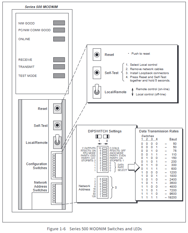
2. Configuration of dip switch
Details of the configuration of the dialing group function
8-bit address dialing set network address binary encoding, address range 1-247 (0 and 248-255 disabled)
10 bit communication dial-up 1-4 baud rate selection, 4-bit combination corresponding to 15 baud rates (50-19200 bps)
10 digit communication dialing code, 5 stop bits, left=1 digit, right=2 digits
10 bit communication dial code 6-7 parity check dial code 6 left=enable check, dial code 7 left=even check/right=odd check
10 bit communication dial-up with 8 transmission modes: left=ASCII, right=RTU
10 bit communication dial-up 9 handshake protocol left=disabled, right=enabled RTS/CTS (adaptive modem)
10 bit communication dial code, 10 memory selection, left=C control relay, right=Y output coil
3. Wiring specifications
Cable requirements: 26 AWG tinned stranded copper wire with aluminum foil+65% braided shielding, PVC outer sheath (UL 30V/60 ℃)
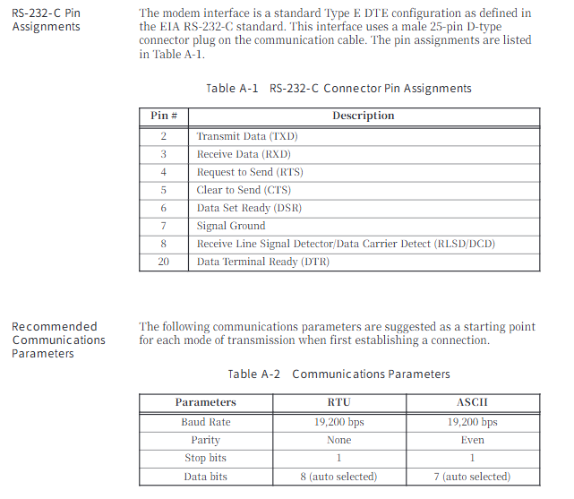
Interface standard: RS-232-C 25 pin D-type connector, supporting three connection methods: no handshake/handshake/modem
Recommended cables: 9-pin crossover cable (P/N: 2601094-8001), 25 pin crossover cable (P/N: VPU200-3605)
Pin definitions: 2=TXD, 3=RXD, 4=RTS, 5=CTS, 7=signal ground, 20=DTR
Modbus communication protocol
1. Comparison of transmission modes
Characteristic ASCII mode RTU mode
Data bits 7 (hexadecimal printable) and 8 (binary)
Verification method LRC (Vertical Redundancy Check) CRC (Cyclic Redundancy Check)
Frame separator start character ":"+end character "CR/LF" 3.5 character silence time
Low transmission efficiency and high efficiency
Applicable scenarios: Low noise environments, industrial complex interference environments
2. Core function codes (17 types)
Function code, function description, maximum number of operations for operating objects
01 Read coil status Y/C coil 2000 pieces
02 Read input status discrete input X 2000
03 Read and hold register V variable memory 125
04 Read Input Register WX Word Input 125
05 Write a single coil Y/C coil 1 (supports broadcasting)
06 Write a single register V variable memory 1 (supports broadcasting)
07 Read 8 status coils inside the abnormal state-
08 Perform diagnostic module self-test/counter reset, etc-
11. Obtain communication event counter, successful message count-
Retrieve the communication event log for the last 64 events-
15 write multiple coils Y/C coils 800 (supports broadcasting)
16 write multiple registers V variable memory 100 (supports broadcasting)
Report 17: Station ID, PLC model/operating status, etc-
3. Abnormal response
Exception identifier: Function code highest position 1 (e.g. 01 → 81)
Core Exception Codes (8 types): 01 (Illegal Function), 02 (Illegal Address), 03 (Illegal Data Value), 04 (Associated Device Failure), 06 (Memory Parity Error), etc
Response mechanism: No response in broadcast mode, single address request returns exception code+checksum
Diagnosis and maintenance
1. Diagnostic testing
Power on self-test: After the module is powered on or reset, it checks the RAM/ROM/processor. If it passes, the NIM GOOD light will turn on
Run time diagnosis: Continuously monitor ROM integrity, PLC communication, watchdog timer, and enter offline mode if there is a fault
User triggers self-test: disconnect network cable → connect loop connector → reset+long press test button for 5 seconds, determine fault through LED status
LED status indicator: 6 LEDs (NIM GOOD/PC GOOD/ON LINE/REC/XMT/TEST), providing intuitive feedback on module status
2. Maintenance tools and operations
MODASST software: DOS environment configuration diagnostic tool, supporting communication parameter settings, function code testing, and troubleshooting
Module reset: Press the reset button to initialize the module, clear the counter and buffer
Firmware version: Supports reading software versions (Release 1.0-3.0) through function code 17
Replacement process: Power off → Pull out old module → Set new module dip code → Insert base → Power on self-test
3. Environment and Protection
Working environment: temperature 0-60 ℃, humidity 5% -95%, non condensing, pollution level 2
Anti interference capability: compliant with IEC 801 standard, anti-static 15 kV, radiation interference level 3
Protection certification: UL 508, CSA 142, FM Class I Div. 2 certification
- YOKOGAWA
- Reliance
- ADVANCED
- SEW
- ProSoft
- WATLOW
- Kongsberg
- FANUC
- VSD
- DCS
- PLC
- man-machine
- Covid-19
- Energy and Gender
- Energy Access
- Renewable Integration
- Energy Subsidies
- Energy and Water
- Net zero emission
- Energy Security
- Critical Minerals
- A-B
- petroleum
- Mine scale
- Sewage treatment
- cement
- architecture
- Industrial information
- New energy
- Automobile market
- electricity
- Construction site
- HIMA
- ABB
- Rockwell
- Schneider Modicon
- Siemens
- xYCOM
- Yaskawa
- Woodward
- BOSCH Rexroth
- MOOG
- General Electric
- American NI
- Rolls-Royce
- CTI
- Honeywell
- EMERSON
- MAN
- GE
- TRICONEX
- Control Wave
- ALSTOM
- AMAT
- STUDER
- KONGSBERG
- MOTOROLA
- DANAHER MOTION
- Bentley
- Galil
- EATON
- MOLEX
- Triconex
- DEIF
- B&W
- ZYGO
- Aerotech
- DANFOSS
- KOLLMORGEN
- Beijer
- Endress+Hauser
- schneider
- Foxboro
- KB
- REXROTH
- YAMAHA
- Johnson
- Westinghouse
- WAGO
- TOSHIBA
- TEKTRONIX
- BENDER
- BMCM
- SMC
- HITACHI
- HIRSCHMANN
- XP POWER
- Baldor
- Meggitt
- SHINKAWA
- Other Brands
- UniOP
- KUKA
- IBA
- Beckhoff
-
LTI SC52.0040.0012.0000.0 - Servo Drive
-
Lti SC52.0040.0012.0000.0 - Servo Drive
-
Milton Industries LTI Tool By Milton LT1240 - 1/2" Drive Lugnut Remover
-
LTi Drives SO84.200.P030.0000.0-W - Servo Spindle Drive
-
LTI DRIVES LSP08-035-320-30-B0R1PY170 - Servo Motor
-
LTI DRIVES SE84.200.SC00.0001.0-W - Servo Drive
-
Lust CDE34.005.W2.2 - Lti Drives Controller
-
LTi SO84.012.0030.0011.2 - ServoOne Servo Drive
-
LTi Drives SO CM-P.0010.11.00.0 - Servo Drive Controller
-
LTi CDE34.017.W3.0 - Servo Drive
-
LTI Drives CDB32.004, C2.0,SH - Positioning Controller
-
LUST CM-CAN1 - LTi DRIVES Communication Module
-
LTi SO84.012.1030.0000.2 - Servo Drive
-
LTI MOOG CDE54.044 - PITCHMASTER FREQUENCY CONVERTER 181-01019
-
MOOG LTI 181-01019 CDE54.044 - PITCHMASTER FREQUENCY CONVERTER
-
Lust LTi Drives CDE34.010,D2.0 - Servo Drive Controller
-
LTI SO84.032.0003.0101.2 - Servo Drive
-
Seagate 9CC132-302 Harris LTI-CS IRT-34-0021-01 - Hard Drive 160GB
-
LTI SO84.032.0003.0001.2 - Servo Drive
-
LTI SO24.007.0070.0000.1 - SERVO CONTROLLER
-
LTi drive CDA32.003.C3.0.H05-01.PC1 - Servo Drive
-
LTI SO84.016.0030.0000.2 - SERVO CONTROLLER
-
LUST LTI CD A34.008,W1.4, BR - SERVO DRIVE
-
MOOG LTI 181-01019 CDE54.044 - PITCHMASTER FREQUENCY CONVERTER
-
LTI MOOG 181-01019 - PITCH Master Servo Drive CDE54.044
-
LTI SERVO ONE SO84.045.0030.0001.2-W - Drive
-
LUST LTi SO84.032.0040.0000.2 - SERVO ONE DRIVE
-
LTi Drives LSH-074-2-30-3 20/T1,G6.1M - SERVO MOTOR
-
LTI SO84.016.0000.0101.2 - servo drive
-
LTI SA54.0550.0033.0000.0 - Servo Drive
-
LTI SA54.0550.0033.0000.0 - Servo Drive
-
LTI LT 4850 - 3/8" Drive 3-Pc Twist Socket Transmission Drain Plug Removal System
-
LTI Tools LT4400-30 Lock Technology - 3/4" Twist Socket 1/2" Drive Lugnut Remover
-
LTI Tools LT-1400C - 1/2 Drive Wheel Torque Extension Tool
-
LTI Tools LT1250 - 1/2" Drive Dual Sided Socket Lug Nut Remover Tool
-
LTI SO84.032.0003.0101.2 - Servo Drive
-
LTI MOOG 181-01019 - PITCH Master Servo Drive CDE54.044
-
MOOG LTI 181-01019 CDE54.044 - PITCHMASTER FREQUENCY CONVERTER
-
MOOG LTI 181-01019 CDE54.044 - PITCHMASTER FREQUENCY CONVERTER
-
MOOG LTI 181-01019 CDE54.044 - PITCHMASTER FREQUENCY CONVERTER
-
LTI SA54.0550.0033.0000.0 - Servo Drive
-
LTI Tools LT-4800 - 7 Piece Twist Socket 3/8" Drive Oil Drain Plug Removal Set
-
LTI SA54.0550.0033.0000.0 - Servo Drive
-
LTI Drive SO24.007.00300000.0 - Servo Drive
-
LTI TOOLS LTI 1400-I - Drive Wheel Torque Extension
-
LTI Tools LT4400-3 - 3/4" 19mm Twist Socket 1/2" Drive Lugnut
-
LTI TOOLS LTI 1400-BB - Drive Wheel Torque Extension
-
LTI SO84.032.0003.0101.2 - Servo Drive
-
LTI Tools LT-4512 - 3/8" Drive 12mm Twist Socket
-
LTI MOTION Luster SO84.032.0003.0001.2 - Servo Drive
-
LTI Tool By Milton LT1600P - 1" Drive Torx Stick
-
LTI Lust VF1424L,HF,OP2,S56 - Variable Frequency Drive
-
LUST CDA32.004,C1.4,H08,B0 - SERVO DFRIVE CM-CAN1 Module
-
LTI SO84.045.0002.0001.2-W - Drive
-
LTI Lust VF1404M,C9,PT1,BR1 - Inverter Type VF1404M
-
LTI SA54.0550.0033.0000.0 - Servo Drive
-
LTI Tools LT-1400C - 1/2" Drive Wheel Torque Extension
-
Lust LTI DRiVES CDA32.006, C3.0, H09 - Variateur De Fr茅quence Frequency Inverter
-
LTI MOOG CDE54.044 - PITCH master SERVO DRIVE
-
LTI MOOG CDE54.044 - PITCH master SERVO DRIVE
-
LTI SO84.143.0020.0101.2-W - servo drive
-
LTI MOTION SC34.0200.0011.0000.0 - Servo drives
-
LTI SO84.032.0003.0001.2 - Servo Drive
-
LTI DRIVES GmbH MS100 - Assembly Set Mounting Kit
-
LTI SO84.032.0003.0001.2 - Servo Drive
-
LTI SO84.032.0003.0001.2 - Servo Drive
-
LTI MOTION SO84.032.0003.0101.2 - servo drive
-
LTI SO84.032.0003.0101.2 - Servo Drive
-
LTI MOOG CDE54.044 - PITCH master SERVO DRIVE
-
LTI MOTION CDE32.004.C2.4 - Servo drives
-
LTI CDD34.032锛學x.x锛孊R锛孭C1 - Servo Drive
-
Lust LTI DRiVES CDA32.006, C3.0, H09 - Inversor De Frecuencia Frequency Inverter
-
Lust SO84.008.0030.1000.0 - Servo One LTi Drive
-
LTI MOTION SO84.032.0003.0101.2 - Servo drives
-
LUST LTi CDA32.004,C1.4 - SERVO DRIVE
-
LTI MOOG CDE54.044 - PITCH Master SERVO DRIVE
-
LTI KEBA CDB32.004 C2.7, SH - PN: 08673530 Frequency Inverter
-
LTI Tools LT-1400C - 1/2" Drive Wheel Torque Extension
-
LTI LT1400-E - 1/2" Drive Wheel Torque Extension
-
LTI MOOG 181-01019 - PITCH master SERVO DRIVE CDE54.044
-
LTI LSN-097-0510-30-560/T1 - Actuator Motor
-
LTI Tools LT 4800 - 7 Piece 3/8" Drive Twist Socket Oil Drain Plug Removal System
-
LTI DRIVES GmbH MS100 - MONTAGESET Assembly Set Mounting Kit
-
Lti SC52.0040.0012.0000.0 - Servo Drive
-
LTI DRIVES GmbH MS100 - Juego De Montaje Assembly Set Mounting Kit
-
LTi DSM4-14.2-21R83-200 - Drives servomoteur Servo Motor
-
MOOG CDE 54.044.GDA - Pitch Master Industrielle Turbine Lti Drive
-
LTI SO24.004.0030.1000.0 - Servo Drive Controller
-
Lti MOOG CDE54.044 - Pitch Master Servo Drive
-
Lust LTI DRiVES CDA32.006, C3.0, H09 - Inverter
-
LTI MOTION GMBH CDB34.006,W3.0,PC1,H39 - Frequency inverter
-
LTI SO84.032.0003.0001.2 - Servo Drive
-
MOOG CDE 54.044.D - Pitch Master Industrielle Turbine Lti Drive
-
LTI TOOLS LT-1460 - 1/2" DRIVE WHEEL TORQUE EXTENSION KIT 5 PIECE SET
-
Lust Cdb32.003, C2.4 - Lti Drives Servoregulador Frecuencia Servo Controller Inverter
-
Lust LTI DRIVES CDA32.006, C3.0, H09 - Frequency Inverter
-
Lust Lti SO82.004.0030.0000.2 - Servo Drive
-
LTI MOTION SC34.0200.0011.0000.0-SL - Servo drives
-
LTI MOTION SA54.0075.0033.0000.0 - Servo drives
-
LTI MOTION SC32.0075.1011.0000.0 - Servo drives
-
LTI Servo-One Junior SO22.006.0080.1000.0 - Servo Controller Servoregler
-
LUST CDA32.004, C1.4, H08, B0 - Servo Drive & LTI CM-CAN1 Module
-
LTI DRIVES LSP08-035-320-30-B0R1PY170 - Servo Motor
-
LUST LTI CDA32.004,C1.4.H08.B0 - SERVO CONTROLLER DRIVES
-
LUST LTi DRiVES CDS44.072LC1.2 - Servo Drive
-
Lti Servo-One Junior SO22.006.0082.1000.0 - Servo Controller Servoregler
-
LUST CDA32.008,C2.0,HF - Lti DRIVES Spindle Drive Inverter
-
LTI SO22.003.0082.0000.0 - Servo Drives One junior Servo Controller Servoregler
-
Lust Lti Drives CM-CAN1 - Communication Module
-
LUST Lti Drives Vf1202s, G8, I6 - Frequency Inverter Drive
-
LTI DRIVES BR-090.03.540.UR.H38 - Bremswiderstand Brake Resistor
-
LTi DRIVES PM-E40.2DRA054P - Wind Turbine Pitch Control Inverter
-
LTi Drives GmbH br-110.01.540-UR - Brake Resistor
-
LTI Drives LSN-097-0960-30-0560/T1,S4,B - Servo Motor
-
LUST CDA34.006.C2.0 - LTI Drives Servoregler
-
LUST LTI DRIVES SERVO ONE JUNIOR SO24.002.0020.0000.1 - Servo Drive Controller
-
LTI MOTION SO84.032.0003.0001.2 - Servo drives
-
LTI DDTD750V2-120 - IBOP ACTUATOR CYLINDER FOR TOP DRIVE
-
LTI CDE32.004, C2.4 - SERVO DRIVE
-
LUST LTI DRIVES CDD34.017 W3.4PC1 - Servo Drive Controller
-
LTI CDA3208,C3,0,HF - AC SERVO DRIVE
-
LUST LTI DRIVES LSH-074-3-30-560/T1,G6.1S - SERVO MOTOR
-
LUST Lti CDB32.004.C2.4.SH - AC Servo Drive
-
LTi CDA32.006, C3.0, H09 - Servo Drive
-
LTI SO22.003.0010.0000.0 - Servo Drive Servo one junior Servoregler Controller
-
LTi Drives DSM4-14.2-21R83-200 - Servo Motor
-
LUST Lti Drives Lsh-097-1-30-560/T1, 1R - Servomotor
-
LTI 1237 - 7 Piece 1/2" Drive Flip Socket Set

K-JIANG

Add: Jimei North Road, Jimei District, Xiamen, Fujian, China
Tell:+86-15305925923