
K-WANG


SIEMENS SIMATIC RF120C Communication Module Operation Guide
SIEMENS SIMATIC RF120C Communication Module Operation Guide
The SIMATIC RF120C Communication Module Operation Guide introduces the application scenarios, installation and connection, configuration parameter allocation, service maintenance, and technical data of the module. It is suitable for SIMATIC S7-1200 controllers (firmware ≥ 3.0) and can be connected to one RFID or optical reader through RS422 interface. It supports a maximum transmission speed of 115.2 kbps and a maximum cable length of 1000m, with a protection level of IP20. It needs to be configured with TIA Portal (STEP 7 V13 and above) and can achieve functions such as reading, writing, and addressing of the responder. Only qualified professionals are allowed to operate it.
1. Product Overview
(1) Application Fields and Core Features
Category key information
Applicable scenarios with SIMATIC S7-1200 controller to achieve data exchange between RFID/optical readers
Compatible with RF200/RF300/RF600 (RF620R/RF630R), MV400/MV500, MOBY D/U series readers
Core feature: 1 RS422 interface, supporting 1 reader connection; Protection level IP20; A single S7-1200 can accommodate up to 3 RF120Cs; Support standard addressing (linear address access)
Software requirements include TIA Portal (STEP 7 Basic/Professional V13 and above), integrated with Ident library and function blocks
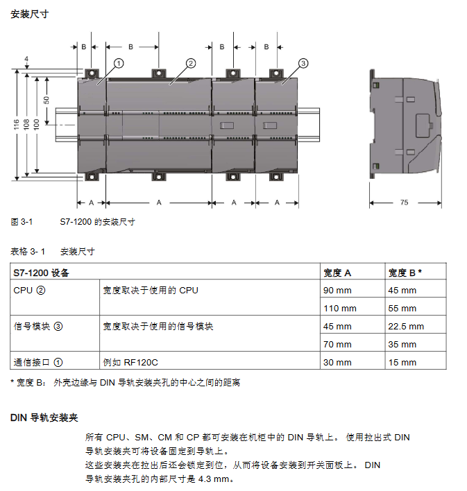
(2) Installation and configuration requirements
Installation position: Adjacent to the left side of S7-1200, with a ventilation gap of 25mm above and below
Installation method: 35mm DIN rail installation, width 30mm, weight 0.15kg
Temperature range: Horizontal installation 0 ° C~55 ° C, vertical installation 0 ° C~45 ° C
2. Installation and Connection
(1) Safety Notice
Power requirements: Safety ultra-low voltage (SELV/LPS), compliant with IEC 60950-1/EN 60950-1/VDE 0805-1
Operation specifications: Power off installation/disassembly, prohibit opening the equipment when powered on; 24V power supply needs to be protected against electromagnetic pulses (such as lightning protection)
Grounding requirement: The module needs to be grounded through the shielding layer
(2) Installation and connection steps
Remove the left bus cover of the S7-1200 CPU, align the RF120C bus connector, and snap it in
Install the CPU and RF120C onto the DIN rail and secure them in place
Connect an external 24V power supply to the top 3-pin socket of RF120C
Connect the reader to the RF120C 9-pin D-type female connector via a D-type cable
Connect the power, close the module front cover, download STEP 7 project data to complete debugging
(3) Power supply and pin allocation
Interface Type Pin Configuration Function Description
External power socket (3-pin) 1-pin (L+):+24VDC (maximum 1A); 2-pin (M): Grounding reference; 3-pin: The grounding connector supplies power to the reader, automatically shuts off and notifies the CPU when overloaded
D-type socket (9-pin, RS422) pin 1: 24VDC; 4 legs:+TxD; 5 pins: GND; 7-foot: - RxD; 8 legs:+RxD; 9-pin: - TxD realizes data transmission with the reader, supports hot swapping
3. Configuration and parameter allocation
(1) Hardware configuration
Configuration path: TIA Portal → Project View → Add S7-1200 → Hardware Catalog → SIMATIC S7-1200 → Communication Module → Identification System → RF120C
Core limitation: Each S7-1200 can be configured with up to 3 RF120C modules
(2) Key parameter group
Explanation of default values for parameter group core settings
Reader parameter group diagnostic message, Ident device/system selection hard error, Ident configuration file selection of connected reader type, triggering hardware diagnostic alarm
Ident device/system parameter group transmission speed, presence check, RF power, transmitter responder type 115.2 kBd, on, 1.00W transmission speed support 19.2/57.6/115.2 kBd; RF power of 0.50~5.00W (depending on the reader)
Reader type parameter group (RF600 only) includes wireless configuration file, multi tag mode, intelligent single tag mode ETSI, UID=EPC-ID, and support for ETSI/FCC/CMIT wireless standards; Multi label mode with optional EPC-ID (8 bytes) or Handle-ID (4 bytes)
(3) Programming and Addressing
Programming method: Program through the Ident instruction of the S7 controller, using function block libraries (Read/Write/Read_SPC-ID, etc.)
Addressing rule: Linear addressing, from the starting address (such as 0x0000) to the ending address, automatically identifying the storage size of the sending responder
Typical address space: RF200 (ISO 15693) starting address 0x0000, ending address 0x002B (44 bytes); RF300 (20 byte EEPROM) starting address 0xFF00, ending address 0xFF13
4. Service and Maintenance
(1) LED status display
Meaning of LED type status
DIAG (red/green) green constant light configuration successful, no errors
DIAG (red/green) flashing green startup/not configured/firmware update
DIAG (red/green) module with constant red light is faulty and needs to be replaced
The LED inside the shell is green (DC 24V), and the external 24V power supply is normal
The yellow LED (Rx) inside the casing is communicating with the reader
There is an error in the red flashing (ERROR) of the LED inside the casing, and the number of flashes corresponds to the type of error
(2) Diagnosis and Error Handling
Diagnostic methods: LED status viewing, TIA Portal online diagnosis, GET-DIAG instruction evaluation, ERROR/STATUS parameter analysis
Error message structure: Status parameter 4 bytes (byte 0: function number; byte 1: error number; byte 2: error code; byte 3: warning)
Common errors: Reader unresponsive (ERROR flashes 3 times), voltage interruption/short circuit (flashes 17 times), parameter allocation error (flashes 21 times)
(3) Module replacement
Configuration storage: RF120C configuration data is stored in S7-1200 CPU
Replacement process: Power off → Disassemble old module → Install new module → Power on → CPU automatically issues configuration data without reloading the project
5. Technical data and appendices
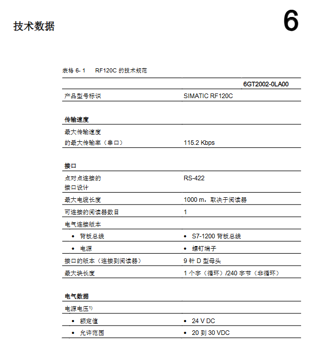
(1) Core technical parameters
Category specifications
Electrical parameters: Power supply voltage of 20~30VDC (rated 24VDC); Backplane bus current consumption 110~250mA; maximum external power supply 1A
The maximum transmission speed of communication parameters is 115.2 kbps; The maximum cable length is 1000m (depending on the reader); Maximum block length of 240 bytes (non cyclic)
Mechanical parameter size 30 × 100 × 75mm; Material Xantar MX 1094 (Ti Grey 24L01); MTBF (40 ° C) 196 years
Environmental parameter storage temperature -40 ° C~70 ° C; anti static discharge 8kV (air)/4kV (contact)
(2) Compliance and ordering data
Certification standards: CE, FCC, cULus, KCC, RoHS (2011/65/EU), ATEX/IECEx explosion-proof certification
Core order number: RF120C module (6GT2002-0LA00); 2m connecting cable (6GT2091-4LH20); Terminal block (6GK5980-1CB00-0DA5)
- YOKOGAWA
- Reliance
- ADVANCED
- SEW
- ProSoft
- WATLOW
- Kongsberg
- FANUC
- VSD
- DCS
- PLC
- man-machine
- Covid-19
- Energy and Gender
- Energy Access
- Renewable Integration
- Energy Subsidies
- Energy and Water
- Net zero emission
- Energy Security
- Critical Minerals
- A-B
- petroleum
- Mine scale
- Sewage treatment
- cement
- architecture
- Industrial information
- New energy
- Automobile market
- electricity
- Construction site
- HIMA
- ABB
- Rockwell
- Schneider Modicon
- Siemens
- xYCOM
- Yaskawa
- Woodward
- BOSCH Rexroth
- MOOG
- General Electric
- American NI
- Rolls-Royce
- CTI
- Honeywell
- EMERSON
- MAN
- GE
- TRICONEX
- Control Wave
- ALSTOM
- AMAT
- STUDER
- KONGSBERG
- MOTOROLA
- DANAHER MOTION
- Bentley
- Galil
- EATON
- MOLEX
- Triconex
- DEIF
- B&W
- ZYGO
- Aerotech
- DANFOSS
- KOLLMORGEN
- Beijer
- Endress+Hauser
- schneider
- Foxboro
- KB
- REXROTH
- YAMAHA
- Johnson
- Westinghouse
- WAGO
- TOSHIBA
- TEKTRONIX
- BENDER
- BMCM
- SMC
- HITACHI
- HIRSCHMANN
- XP POWER
- Baldor
- Meggitt
- SHINKAWA
- Other Brands
- UniOP
- KUKA
- IBA
- Beckhoff
-
LTI SC52.0040.0012.0000.0 - Servo Drive
-
Lti SC52.0040.0012.0000.0 - Servo Drive
-
Milton Industries LTI Tool By Milton LT1240 - 1/2" Drive Lugnut Remover
-
LTi Drives SO84.200.P030.0000.0-W - Servo Spindle Drive
-
LTI DRIVES LSP08-035-320-30-B0R1PY170 - Servo Motor
-
LTI DRIVES SE84.200.SC00.0001.0-W - Servo Drive
-
Lust CDE34.005.W2.2 - Lti Drives Controller
-
LTi SO84.012.0030.0011.2 - ServoOne Servo Drive
-
LTi Drives SO CM-P.0010.11.00.0 - Servo Drive Controller
-
LTi CDE34.017.W3.0 - Servo Drive
-
LTI Drives CDB32.004, C2.0,SH - Positioning Controller
-
LUST CM-CAN1 - LTi DRIVES Communication Module
-
LTi SO84.012.1030.0000.2 - Servo Drive
-
LTI MOOG CDE54.044 - PITCHMASTER FREQUENCY CONVERTER 181-01019
-
MOOG LTI 181-01019 CDE54.044 - PITCHMASTER FREQUENCY CONVERTER
-
Lust LTi Drives CDE34.010,D2.0 - Servo Drive Controller
-
LTI SO84.032.0003.0101.2 - Servo Drive
-
Seagate 9CC132-302 Harris LTI-CS IRT-34-0021-01 - Hard Drive 160GB
-
LTI SO84.032.0003.0001.2 - Servo Drive
-
LTI SO24.007.0070.0000.1 - SERVO CONTROLLER
-
LTi drive CDA32.003.C3.0.H05-01.PC1 - Servo Drive
-
LTI SO84.016.0030.0000.2 - SERVO CONTROLLER
-
LUST LTI CD A34.008,W1.4, BR - SERVO DRIVE
-
MOOG LTI 181-01019 CDE54.044 - PITCHMASTER FREQUENCY CONVERTER
-
LTI MOOG 181-01019 - PITCH Master Servo Drive CDE54.044
-
LTI SERVO ONE SO84.045.0030.0001.2-W - Drive
-
LUST LTi SO84.032.0040.0000.2 - SERVO ONE DRIVE
-
LTi Drives LSH-074-2-30-3 20/T1,G6.1M - SERVO MOTOR
-
LTI SO84.016.0000.0101.2 - servo drive
-
LTI SA54.0550.0033.0000.0 - Servo Drive
-
LTI SA54.0550.0033.0000.0 - Servo Drive
-
LTI LT 4850 - 3/8" Drive 3-Pc Twist Socket Transmission Drain Plug Removal System
-
LTI Tools LT4400-30 Lock Technology - 3/4" Twist Socket 1/2" Drive Lugnut Remover
-
LTI Tools LT-1400C - 1/2 Drive Wheel Torque Extension Tool
-
LTI Tools LT1250 - 1/2" Drive Dual Sided Socket Lug Nut Remover Tool
-
LTI SO84.032.0003.0101.2 - Servo Drive
-
LTI MOOG 181-01019 - PITCH Master Servo Drive CDE54.044
-
MOOG LTI 181-01019 CDE54.044 - PITCHMASTER FREQUENCY CONVERTER
-
MOOG LTI 181-01019 CDE54.044 - PITCHMASTER FREQUENCY CONVERTER
-
MOOG LTI 181-01019 CDE54.044 - PITCHMASTER FREQUENCY CONVERTER
-
LTI SA54.0550.0033.0000.0 - Servo Drive
-
LTI Tools LT-4800 - 7 Piece Twist Socket 3/8" Drive Oil Drain Plug Removal Set
-
LTI SA54.0550.0033.0000.0 - Servo Drive
-
LTI Drive SO24.007.00300000.0 - Servo Drive
-
LTI TOOLS LTI 1400-I - Drive Wheel Torque Extension
-
LTI Tools LT4400-3 - 3/4" 19mm Twist Socket 1/2" Drive Lugnut
-
LTI TOOLS LTI 1400-BB - Drive Wheel Torque Extension
-
LTI SO84.032.0003.0101.2 - Servo Drive
-
LTI Tools LT-4512 - 3/8" Drive 12mm Twist Socket
-
LTI MOTION Luster SO84.032.0003.0001.2 - Servo Drive
-
LTI Tool By Milton LT1600P - 1" Drive Torx Stick
-
LTI Lust VF1424L,HF,OP2,S56 - Variable Frequency Drive
-
LUST CDA32.004,C1.4,H08,B0 - SERVO DFRIVE CM-CAN1 Module
-
LTI SO84.045.0002.0001.2-W - Drive
-
LTI Lust VF1404M,C9,PT1,BR1 - Inverter Type VF1404M
-
LTI SA54.0550.0033.0000.0 - Servo Drive
-
LTI Tools LT-1400C - 1/2" Drive Wheel Torque Extension
-
Lust LTI DRiVES CDA32.006, C3.0, H09 - Variateur De Fr茅quence Frequency Inverter
-
LTI MOOG CDE54.044 - PITCH master SERVO DRIVE
-
LTI MOOG CDE54.044 - PITCH master SERVO DRIVE
-
LTI SO84.143.0020.0101.2-W - servo drive
-
LTI MOTION SC34.0200.0011.0000.0 - Servo drives
-
LTI SO84.032.0003.0001.2 - Servo Drive
-
LTI DRIVES GmbH MS100 - Assembly Set Mounting Kit
-
LTI SO84.032.0003.0001.2 - Servo Drive
-
LTI SO84.032.0003.0001.2 - Servo Drive
-
LTI MOTION SO84.032.0003.0101.2 - servo drive
-
LTI SO84.032.0003.0101.2 - Servo Drive
-
LTI MOOG CDE54.044 - PITCH master SERVO DRIVE
-
LTI MOTION CDE32.004.C2.4 - Servo drives
-
LTI CDD34.032锛學x.x锛孊R锛孭C1 - Servo Drive
-
Lust LTI DRiVES CDA32.006, C3.0, H09 - Inversor De Frecuencia Frequency Inverter
-
Lust SO84.008.0030.1000.0 - Servo One LTi Drive
-
LTI MOTION SO84.032.0003.0101.2 - Servo drives
-
LUST LTi CDA32.004,C1.4 - SERVO DRIVE
-
LTI MOOG CDE54.044 - PITCH Master SERVO DRIVE
-
LTI KEBA CDB32.004 C2.7, SH - PN: 08673530 Frequency Inverter
-
LTI Tools LT-1400C - 1/2" Drive Wheel Torque Extension
-
LTI LT1400-E - 1/2" Drive Wheel Torque Extension
-
LTI MOOG 181-01019 - PITCH master SERVO DRIVE CDE54.044
-
LTI LSN-097-0510-30-560/T1 - Actuator Motor
-
LTI Tools LT 4800 - 7 Piece 3/8" Drive Twist Socket Oil Drain Plug Removal System
-
LTI DRIVES GmbH MS100 - MONTAGESET Assembly Set Mounting Kit
-
Lti SC52.0040.0012.0000.0 - Servo Drive
-
LTI DRIVES GmbH MS100 - Juego De Montaje Assembly Set Mounting Kit
-
LTi DSM4-14.2-21R83-200 - Drives servomoteur Servo Motor
-
MOOG CDE 54.044.GDA - Pitch Master Industrielle Turbine Lti Drive
-
LTI SO24.004.0030.1000.0 - Servo Drive Controller
-
Lti MOOG CDE54.044 - Pitch Master Servo Drive
-
Lust LTI DRiVES CDA32.006, C3.0, H09 - Inverter
-
LTI MOTION GMBH CDB34.006,W3.0,PC1,H39 - Frequency inverter
-
LTI SO84.032.0003.0001.2 - Servo Drive
-
MOOG CDE 54.044.D - Pitch Master Industrielle Turbine Lti Drive
-
LTI TOOLS LT-1460 - 1/2" DRIVE WHEEL TORQUE EXTENSION KIT 5 PIECE SET
-
Lust Cdb32.003, C2.4 - Lti Drives Servoregulador Frecuencia Servo Controller Inverter
-
Lust LTI DRIVES CDA32.006, C3.0, H09 - Frequency Inverter
-
Lust Lti SO82.004.0030.0000.2 - Servo Drive
-
LTI MOTION SC34.0200.0011.0000.0-SL - Servo drives
-
LTI MOTION SA54.0075.0033.0000.0 - Servo drives
-
LTI MOTION SC32.0075.1011.0000.0 - Servo drives
-
LTI Servo-One Junior SO22.006.0080.1000.0 - Servo Controller Servoregler
-
LUST CDA32.004, C1.4, H08, B0 - Servo Drive & LTI CM-CAN1 Module
-
LTI DRIVES LSP08-035-320-30-B0R1PY170 - Servo Motor
-
LUST LTI CDA32.004,C1.4.H08.B0 - SERVO CONTROLLER DRIVES
-
LUST LTi DRiVES CDS44.072LC1.2 - Servo Drive
-
Lti Servo-One Junior SO22.006.0082.1000.0 - Servo Controller Servoregler
-
LUST CDA32.008,C2.0,HF - Lti DRIVES Spindle Drive Inverter
-
LTI SO22.003.0082.0000.0 - Servo Drives One junior Servo Controller Servoregler
-
Lust Lti Drives CM-CAN1 - Communication Module
-
LUST Lti Drives Vf1202s, G8, I6 - Frequency Inverter Drive
-
LTI DRIVES BR-090.03.540.UR.H38 - Bremswiderstand Brake Resistor
-
LTi DRIVES PM-E40.2DRA054P - Wind Turbine Pitch Control Inverter
-
LTi Drives GmbH br-110.01.540-UR - Brake Resistor
-
LTI Drives LSN-097-0960-30-0560/T1,S4,B - Servo Motor
-
LUST CDA34.006.C2.0 - LTI Drives Servoregler
-
LUST LTI DRIVES SERVO ONE JUNIOR SO24.002.0020.0000.1 - Servo Drive Controller
-
LTI MOTION SO84.032.0003.0001.2 - Servo drives
-
LTI DDTD750V2-120 - IBOP ACTUATOR CYLINDER FOR TOP DRIVE
-
LTI CDE32.004, C2.4 - SERVO DRIVE
-
LUST LTI DRIVES CDD34.017 W3.4PC1 - Servo Drive Controller
-
LTI CDA3208,C3,0,HF - AC SERVO DRIVE
-
LUST LTI DRIVES LSH-074-3-30-560/T1,G6.1S - SERVO MOTOR
-
LUST Lti CDB32.004.C2.4.SH - AC Servo Drive
-
LTi CDA32.006, C3.0, H09 - Servo Drive
-
LTI SO22.003.0010.0000.0 - Servo Drive Servo one junior Servoregler Controller
-
LTi Drives DSM4-14.2-21R83-200 - Servo Motor
-
LUST Lti Drives Lsh-097-1-30-560/T1, 1R - Servomotor
-
LTI 1237 - 7 Piece 1/2" Drive Flip Socket Set

K-JIANG

Add: Jimei North Road, Jimei District, Xiamen, Fujian, China
Tell:+86-15305925923