
K-WANG


Westinghouse ePX3500 Electric High Voltage Cleaning Machine
Flow parameters: maximum water flow rate of 1.76 US GPM (6.66 LPM), rated water flow rate of 1.2 US GPM (4.54 LPM).
Power parameters: Input 120V AC, 60Hz, 13A, equipped with Class A GFCI leakage protection plug, double insulation design.
Applicable water source: Only cold water (tap water) is supported, and the use of hot water, lake water, pool water, etc. is prohibited. The water source pressure should not exceed 150 PSI.
Westinghouse ePX3500 Electric High Voltage Cleaning Machine
Core parameters and product configuration
1. Key specifications
Pressure parameters: maximum pressure 2500 PSI, rated pressure 2000 PSI.
Flow parameters: maximum water flow rate of 1.76 US GPM (6.66 LPM), rated water flow rate of 1.2 US GPM (4.54 LPM).
Power parameters: Input 120V AC, 60Hz, 13A, equipped with Class A GFCI leakage protection plug, double insulation design.
Applicable water source: Only cold water (tap water) is supported, and the use of hot water, lake water, pool water, etc. is prohibited. The water source pressure should not exceed 150 PSI.
2. Core configuration
Cleaning accessories: 0 ° turbine nozzle (high-pressure cleaning), 15 °/25 ° nozzle (medium pressure cleaning), soap nozzle (low-pressure spraying).
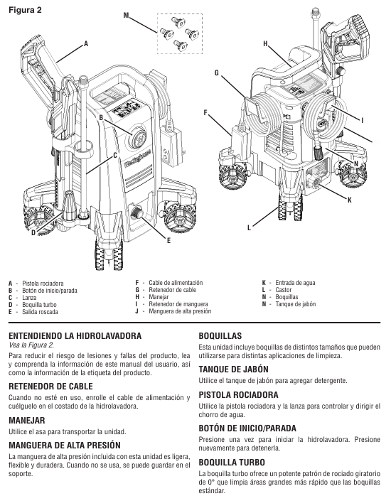
Body components: high-pressure hose, spray gun, extension rod, soap box, roller (easy to move), cable storage rack, hose storage rack.
Safety configuration: trigger safety lock (to prevent accidental contact), GFCI leakage protection (to be tested monthly), 20A circuit breaker (overload protection).
Core functions and usage scenarios
1. Core functions
Multi scenario cleaning: By changing the nozzle to meet different needs, high-pressure nozzles can remove stubborn stains and paint peeling, medium pressure nozzles are suitable for brick and stone roads, and soap nozzles can be used with specialized cleaning agents to clean vehicles, doors, and windows.
Automatic start stop: When the trigger is triggered, the machine starts and automatically stops when released, reducing energy consumption and wear.
Convenient operation: The roller design is easy to move, components can be quickly assembled and disassembled, and cables and hoses have dedicated storage structures.
2. Applicable and taboo scenarios
Applicable for cleaning hard surfaces such as vehicles, decks, sidewalks, fences, and exterior walls of buildings.
Taboo: Do not directly spray personnel, animals, electrical equipment, glass (easily broken); Do not use in damp environments, flammable dust/liquid areas; Not suitable for cleaning medical equipment or precision instruments.
Complete operation process (assembly → use → shutdown → maintenance)
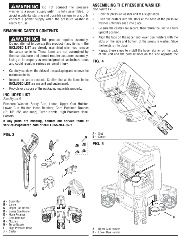
1. Assembly steps (completed within 10 minutes)
Install the roller: Tilt the body, align the roller with the bottom slot, and push it in firmly until you hear a "click" sound, ensuring that the roller is securely installed (you can gently shake it for testing).
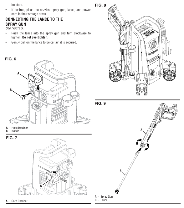
Fixed storage components: Align the spray gun storage rack, hose storage rack, and cable storage rack with the reserved card slot on the body, slide them into place, and tighten the fixing screws (if any).
Connect high-pressure hose:
Take out the high-pressure hose, align one end with the water outlet of the machine body, press the hose buckle and push it in, and tighten the locking ring clockwise.
Align the other end with the spray gun interface, press the buckle and tighten it, gently pull the hose to confirm a secure connection.
Connect water source:
Check if the filter inside the water inlet of the aircraft is intact and unobstructed (if there are impurities, rinse with clean water).
Connect one end of the garden hose to the faucet and the other end to the water inlet of the machine. Tighten the buckle clockwise and turn on the faucet to test for water leakage.
Assemble spray gun and nozzle:
Insert the extension rod into the spray gun interface, tighten clockwise (do not apply excessive force to avoid damaging the thread), and gently pull to confirm fixation.
Select the desired nozzle, align it with the front end interface of the extension rod and press it. Once you hear the snap sound, it will be installed in place; Press the buckle and pull out the nozzle during disassembly.
2. Usage steps (divided into regular cleaning and cleaning with cleaning agents)
(1) Regular cleaning (without cleaning agents)
Preparation before startup:
Turn on the faucet to ensure smooth water flow and no impurities.
Unlock the safety lock of the spray gun trigger, press the trigger to release the air and residual impurities in the pipeline until there are no bubbles in the continuous water flow, and then lock the safety lock.
Insert the power plug into the grounding socket and ensure that the plug is dry.
Startup and Cleaning:
Press the "start stop button" on the machine body, and the machine will automatically stop after running for 1-2 seconds (the automatic start stop function is normal).
Unlock the trigger safety lock, press the trigger, the machine starts and sprays high-pressure water flow to start cleaning.
Cleaning technique: Starting from the bottom of the surface, clean upwards in a left-right translation to avoid water flow from top to bottom (which may leave water marks); For stubborn stains, the distance between the nozzle and the surface can be shortened (but not less than 15cm), or the 0 ° turbine nozzle can be replaced.
Shutdown operation:
Release the trigger, the machine will automatically stop, and lock the trigger safety lock.
Turn off the faucet and press the trigger to release any residual pressure in the system.
Disconnect the power supply, wrap the cable around the storage rack, wrap the high-pressure hose around the hose storage rack, and place the spray gun into the storage rack.
(2) Cleaning with cleaning agent
Preparation: Pour the specialized cleaning agent for the high-pressure cleaning machine into the soap box in proportion and cover the box tightly.
Replace nozzle: After turning off the power and releasing the pressure, remove the current nozzle and install the soap nozzle.
Cleaning operation:
Turn on the water source and power, press the trigger, and wait for 3-5 seconds (to allow the cleaning agent to be sucked into the pipeline) until the water flow contains the cleaning agent.
Spray at a uniform speed onto the dry surface, ensuring even coverage of the cleaning agent, and let it sit for 1-2 minutes (do not dry out).
Turn off the power, replace with a 25 ° nozzle, turn on the water source and power, rinse the surface with clean water until there is no residue of cleaning agent.
Follow up processing: Empty the soap box, pour in clean water, install a soap nozzle, press the trigger to flush the pipeline for 1 minute to avoid blockage caused by residual cleaning agents.
3. Daily maintenance and regular maintenance
(1) Maintenance after each use (completed within 5 minutes)
Cleaning nozzle: Remove the nozzle, use specialized cleaning tools or fine needles to clean impurities (such as mud, residue of cleaning agent) in the nozzle hole, and then rinse with clean water.
Cleaning the inlet filter: Unscrew the inlet connector, remove the filter, rinse it with clean water, and reinstall it to ensure that the filter is not damaged (missing the filter can cause impurities to enter the pump body and cause wear).
Drain residual water from the pipeline: Turn off the water source, press the trigger to release residual water, disconnect the high-pressure hose and garden hose, tilt the machine body to drain the accumulated water in the inlet.
Cleaning the body: Wipe the dust and stains on the surface of the body with a damp cloth, do not rinse the body with high-pressure water flow (to avoid water ingress to electrical components), and do not use corrosive cleaning agents such as gasoline and solvents.
(2) Regular maintenance (monthly/every 20 hours of use)
Check the high-pressure hose: Check whether the hose is damaged, bulging, loose joints, and whether the sealing ring is aging (if there is water leakage, replace the sealing ring or hose).
Lubrication sealing ring: Apply a small amount of non water soluble grease (such as Vaseline) on the sealing ring of the high-pressure hose joint and spray gun interface to extend the service life of the sealing ring.
Test GFCI plug: Follow the steps of "leakage protection maintenance" mentioned earlier to ensure that the protection function is normal.
Check nozzle wear: If the nozzle hole becomes larger and the spraying direction deviates, it indicates that it has been worn and needs to be replaced (wear can cause a decrease in pressure and cleaning efficiency).
(3) Long term storage and maintenance (not used for more than one month)
Thoroughly clean: Follow the "maintenance after each use" steps to clean the nozzle, filter screen, and pipeline, ensuring that there is no residual cleaning agent.
Drain water: Disconnect all pipelines, press the trigger to release residual water in the pump body, and tilt the machine body for multi angle drainage.
Pump body protection: It is recommended to use commercial pump body protectants (operate according to the instructions) to prevent the pump body seals from drying out and rusting inside.
Storage requirements:
Store in a dry, ventilated, and heated room with a temperature not lower than 4.5 ℃ (to prevent residual moisture from freezing and expanding, which may cause the pump body to crack).
Disassemble the nozzle, spray gun, and extension rod, clean them and place them in the storage rack. Wrap the high-pressure hose and cable neatly to avoid squeezing or bending.
Stay away from flammable materials, high temperature sources (such as heating, stoves), and corrosive gas environments.
Common troubleshooting (quick problem-solving)
Possible causes and solutions for fault phenomena
The machine cannot start. 1. The power supply is not connected properly or the GFCI plug is not reset; 2. The system pressure has not been released; 3. Motor malfunction: 1. Check if the plug is securely plugged in and press the GFCI "RESET" button; 2. Press the trigger of the spray gun to release pressure; 3. If it still cannot be started, contact after-sales service
There is power supply but no water flow/intermittent water flow. 1. The water source is not turned on or the water pressure is insufficient; 2. The inlet filter is clogged; 3. nozzle blockage; 4. Hose bending/leakage 1. Turn on the faucet and ensure that the water source pressure is ≥ 20 PSI; 2. Disassemble and clean the inlet filter screen; 3. Clean or replace the nozzle; 4. Sort out the hoses and check if the joints are tightened
Insufficient pressure: 1. nozzle wear or blockage; 2. Low water source pressure; 3. Aging of hoses (internal collapse); 4. Wear of pump body seal 1. Clean or replace the nozzle; 2. Change the water source (such as taking water from a bucket and switching to tap water); 3. Replace the high-pressure hose; 4. Contact after-sales service for pump body maintenance
Leakage at the connection point: 1. Damaged or missing sealing ring; 2. The joint is not tightened; 3. Damaged hose: 1. Replace the sealing ring with the corresponding specification; 2. Tighten the joint clockwise (do not apply excessive force); 3. Damaged hoses need to be replaced immediately
The machine will automatically stop after running for 2 seconds. The automatic start stop function is normal (if the trigger is not pressed, the pump will stop after the priming is completed). Pressing the trigger of the spray gun can start it without maintenance; If the machine stops frequently after pressing the trigger, check if the nozzle is blocked or if the pipeline is stuck
The trigger cannot be locked, and the safety lock is stuck or damaged. Check if there are impurities stuck in the safety lock, rinse with clean water, and try to operate it; If it still cannot be locked, the trigger assembly of the spray gun needs to be replaced
GFCI plug frequently trips 1. Circuit leakage; 2. The specifications of the extension cable do not match; 3. Internal electrical failure of the machine: 1. Stop using and check if the plug and cable are damaged; 2. Replace the extension cable that meets the requirements; 3. If it still trips, contact after-sales maintenance for repair
Maintenance and Storage
1. Daily maintenance
After each use: empty the soap box, inject clean water and rinse the pipeline through the soap nozzle; Clean the nozzle (use specialized tools or fine needles to remove blockages); Clean the inlet filter screen.
Regular maintenance: monthly testing of GFCI leakage protection; Regularly inspect high-pressure hoses and sealing rings (lubricated with non water soluble grease), and replace hoses immediately if they are damaged (non repairable).
2. Storage requirements
Environmental conditions: Store in a dry, heated indoor environment with a temperature not lower than 4.5 ℃ (to prevent the pump body from freezing and cracking), away from flammable materials and high temperature sources.
Preparation before storage: Disconnect all pipelines and drain any residual water from the pump body; Disassemble the nozzle and spray gun, clean and store them; Use pump body protector (optional) to extend the lifespan.
Common troubleshooting
Possible causes and solutions for the fault phenomenon
After starting up, there is no water flow. The water source is not turned on, the inlet filter is blocked, the hose is bent to open the water source, the filter is cleaned, and the hose is straightened
Insufficient pressure/intermittent discharge nozzle blockage, insufficient water source pressure to clean nozzle, replacement of qualified water source
The sealing ring at the connection is damaged/missing due to water leakage, the thread is not tightened, replace the sealing ring, and tighten the connection again
The automatic start stop function of the machine stops after running for 2 seconds (without pressing the trigger) and can be started by pressing the trigger, no maintenance is required
GFCI plug cannot reset due to circuit leakage, plug damage and stop using. Contact after-sales service to replace the plug
The spray gun cannot lock the trigger and the safety lock is faulty. Check if the safety lock is stuck and if it is damaged, it needs to be replaced
- YOKOGAWA
- Reliance
- ADVANCED
- SEW
- ProSoft
- WATLOW
- Kongsberg
- FANUC
- VSD
- DCS
- PLC
- man-machine
- Covid-19
- Energy and Gender
- Energy Access
- Renewable Integration
- Energy Subsidies
- Energy and Water
- Net zero emission
- Energy Security
- Critical Minerals
- A-B
- petroleum
- Mine scale
- Sewage treatment
- cement
- architecture
- Industrial information
- New energy
- Automobile market
- electricity
- Construction site
- HIMA
- ABB
- Rockwell
- Schneider Modicon
- Siemens
- xYCOM
- Yaskawa
- Woodward
- BOSCH Rexroth
- MOOG
- General Electric
- American NI
- Rolls-Royce
- CTI
- Honeywell
- EMERSON
- MAN
- GE
- TRICONEX
- Control Wave
- ALSTOM
- AMAT
- STUDER
- KONGSBERG
- MOTOROLA
- DANAHER MOTION
- Bentley
- Galil
- EATON
- MOLEX
- Triconex
- DEIF
- B&W
- ZYGO
- Aerotech
- DANFOSS
- KOLLMORGEN
- Beijer
- Endress+Hauser
- schneider
- Foxboro
- KB
- REXROTH
- YAMAHA
- Johnson
- Westinghouse
- WAGO
- TOSHIBA
- TEKTRONIX
- BENDER
- BMCM
- SMC
- HITACHI
- HIRSCHMANN
- XP POWER
- Baldor
- Meggitt
- SHINKAWA
- Other Brands
- UniOP
- KUKA
- IBA
-
Woodward 9905-373 - Digital Synchronizer And Load Controller
-
WOODWARD MAGNETIC PICKUPS - Sensor
-
WOODWARD GCP-30 - Steuertafel for Industrial Regulator Genset Control Package
-
WOODWARD GOVERNOR 9907-1183 REV A - 505 ENHANCED TURBINE CONTROL
-
WOODWARD 9907-173 REV B - Module Load Sharing 120 Volt
-
WOODWARD 9907-014 - 2301A controller
-
Woodward 9905-029 - SPM-A Synchronizer Module Rev C
-
WOODWARD 8440-1799 EASYGEN-350 REV B - Genset Controller
-
WOODWARD 5466-258 REV M - SIMPLEX DISCRETE I/O MODULE
-
Woodward 8440-1884 C - Controller Easygen 2500-5
-
Woodward 8441-1153 - Monitoring Unit 250VAC
-
WOODWARD 8406-120 REV G - EGCP-2 DIGITAL CONTROL
-
Woodward 8273-584 - Atlas-ii Digital Control
-
Woodward 8272-582 - APM Motor Control 8272582
-
Woodward 9905-377 Rev. A - 2301A Load Sharing and Speed Control
-
WOODWARD 8272-517 - Pm Motor Control
-
WOODWARD 9905-797 REV.B - DIGITAL SYNCHRONIZER AND LOAD CONTROL DSLC-D
-
WOODWARD 8272-582 - APM MOTOR CONTROL
-
Woodward Seg FP2-8-24 - Emergency Power Telecommunications Module NP2
-
WOODWARD 2001-12E2U1B1S1A - Fuel Shut Off Valve Stop Solenoid Valve 2000-4505
-
Woodward 8440-1884 K - Genset Controller Easygen-2500-5
-
Woodward 9905-760 - Linknet Termination Module
-
Woodward 8404-009 - Proact Digital Plus Front Panel Rev. H
-
Woodward 8271-651 - Digital Speed Reference
-
Woodward 3077-474C - 8605895 5501-031 D Circuit Module
-
WOODWARD 5466-257 REV.-C - NETCON 5000 MODEL REMOTE TRANSCEIVER I/O MODULE
-
Woodward 8273-101 Rev: A - 2301D Digital Load Sharing and Speed Control
-
WOODWARD 8272-799 - 2301A SPEED CONTROL WITH REMOTE REFERENCE REV:C
-
Woodward 8272-517 - PM Motor Control
-
Woodward 8290-048 8290048 Rev. F - Generator Load Sensor
-
woodward 8273-1012 rev c - 2301e Load Sharing and Speed Control
-
WOODWARD 9905-797 - DIGITAL SYNCHRONIZER AND LOAD CONTROL FOR 3 PHASE GENERATORS
-
WOODWARD 8280-3014 - 723 PLUS DIGITAL CONTROL REV NEW
-
WOODWARD 8440-1884 REV G - GENSET CONTROLLER EASYGEN-2500-5/P1
-
Woodward 8272-683 K - Digital Reference
-
WOODWARD 9907-014 - SPEED CONTROL 2301A REV H
-
Woodward Type UG-8 P/N 037260 - Governor R.P.M 1075-1650 Motor KM58-20
-
WOODWARD 9905-970 - LINKNET 6 CHANNEL 100 OHM RTD Rev:J
-
Woodward 9907-1183 Rev C - Steam Turbine Digital SCREEN 505E Turbine Control
-
Woodward 8440-1614 - GCP-30 Genset Control Package, Rev: F, Type 1, E231544
-
Woodward DC11006-304-024 - ACTUOTOR DYNA ACTUATOR - BARBER-COLMAN
-
Woodward 9905-971 - LINKNET 6 CHANNEL 100 OHM RTD Rev:K
-
Woodward DYNK-10249 - Actuator Controller Kit - DYNA 2000
-
Woodward LR21035 - MFR1 MULTI FUNCTION RELAY REV F
-
Woodward 8440-1831 - EASYGEN 3200-5 P/N: REV. G Gererator Controller
-
Woodward 8272-516 - PM MOTOR CONTROL REV J
-
Woodward 8440-2080 - EASYGEN 2000 genset controller EASYGEN-2300-5/P1
-
Woodward 505DE - Digital Control System
-
Woodward 701 - Digital Speed Control 18-40 VDC 4-20 MA
-
Woodward 8440-1799 - EASYGEN-350 REV B
-
Woodward 8272-582 - Apm Motor Control 100-220v AC/DC
-
Woodward 5501-031 D - 3077-474C 8605895 Circuit Module
-
Woodward XD1-T - XD1T55SAT TRANSFORMER DIFFERENTIAL PROTECTION RELAY
-
Woodward 8272-517 - PM Motor Control 220vac
-
Woodward 8934-658 - Repair Kit UG8D Governor
-
Woodward 5437 18 - module netcon derivative analog rev.A
-
Woodward 8272-171 A - Pm Motor Control
-
Woodward MRN3-1/2 - SEG mains uncoupling relay MRN314D mains decoupling relay
-
Woodward 9905-373 - Digital Synchronizer and Load Control 18-40 VDC Rev P
-
Woodward 5431-640 C - Dual Dynamics 1000 Series Speed Control Module
-
Woodward 5501-031 D - 3077-474C 8605895 Circuit Module
-
Woodward 9907-247 - 828 DIGITAL CONTROL
-
Woodward 8440-1855-G - EASYGEN-2200-5 /P1 12/24VDC GENSET CONTROLLER
-
Woodward NC3-2-8 (NO) - GENERATOR CONTROLLER
-
Woodward 8271-467 K - 2301 LOAD SHARING AND SPEED CONTROL PART NO:
-
Woodward 8440-2177 A - SPM-D2-10 Digital Synchronising Controller
-
Woodward LXMG1614E-14-11 - CCFL and UV Lamps Inverter Module
-
Woodward 8270-990 - signal converter
-
Woodward 9905-068 - LOW VOLTAGE 2301A LOAD SHARING & SPEED CONTOL P/N:
-
Woodward 8901-051 - BOOSTER SERVOMOTOR, SINGLE CYLINDER, 2:1
-
Woodward 8444-1024 D - MWS4-55M CONTROL MODULE UNIT
-
Woodward 5448-914 - GCP-20 Genset Control GCP-20 REV D P/n:
-
Danfoss BHA-1 018-1942 - Hydraulic Actuator
-
Woodward 9905-001 L - SPM-A SYNCHRONIZER
-
Woodward 5464-850 - Module
-
Woodward 5501-371 - Micronet Simplex Mpu Aio Rev C
-
Woodward 8272-132 B - POWER SENSOR
-
Woodward 9907-028 - SPM-A Synchronizer
-
Woodward SA-3678-AM-2 - Overspeed Electric Governor, Model ESSE2-AM
-
Woodward E8250-502 - GOVERNOR ACTUATOR
-
Woodward 8440-1884 J - Controller EASYGEN-2500-5
-
Woodward 5441-693 - DIGITAL I/O MODULE -MISSING PART
-
Woodward SA-4450 - Speed Controller APECS 3100 For Magnetic Pickup
-
Woodward 9903-466 - 701 DIGITAL SPEED CONTROL REV G
-
Woodward 1765-843 - Governor Speed Adjusting Motor P/N Type: SMM40 220V AC 50/60Hz
-
Woodward 9905-760 - Linknet Termination Module
-
Woodward 9907-247 - 828 DIGITAL CONTROL UNIT REV K
-
Woodward 5484-721 - motor
-
Woodward 8440-1734 - MFR-2 Rev.A Multi Function Relay MFR-2
-
Woodward CSC3SUWA - Controller
-
Woodward 8440-1667 - REV B SPM-D1010B/XN
-
Woodward 8406-120 - egcp-2 digital control
-
Woodward DPG-2201-002 - DIGITAL CONTROLLER REV D
-
Woodward 8272-516 - Pm Engine Control Rev J
-
Woodward 8440-1831 - EASYGEN 3200-5 P/N: REV. K - WITHOUT ACCESSORIES
-
Woodward 8273-101 - LOAD SHARING & SPEED CONTROL
-
Woodward 8440-1855-G - EASYGEN-2200-5 /P1 12/24VDC GENSET CONTROLLER
-
Woodward 9907-247 - 828 DIGITAL CONTROL UNIT REV K
-
Woodward LR21035 - MFR1 MULTI FUNCTION RELAY REV J
-
Woodward 8404-009 - PROACT DIGITAL PLUS FRONT PANEL REV J
-
Woodward 9905-204 - Rev N SPM-A synchronizer
-
Woodward 8521-367 - UG-8 P/N r R.P.M 750-1280 Governor / UG8
-
Woodward 9907-175 - Load Sharing Module Rev. B
-
Woodward 5464-645 - DRIVER MODULE REV A 2C ACT DRIVE
-
Woodward 8404-009 - PROACT DIGITAL PLUS FRONT PANEL REV J
-
Woodward 9907-175 - Load Sharing Module Rev. B
-
Woodward 8406-102 - Rev A EGCP-2 Digital Control Engine Generator 8406102
-
Woodward EASYGEN-2500-5 - Controller Genset
-
Woodward 8440-2082 - Controller
-
Woodward 8272-516 - PM MOTOR CONTROL REV J
-
Woodward 9905-373 - Digital Synchronizer and Load Control 18-40 VDC Rev P
-
Woodward 5501-429 - Actuator Controller 25mA 2 Channel , (UPP)
-
Woodward 8440-1869 - SPM-D10 Synchronizing System Control-SPM-D10B/PSY4-F-D
-
Woodward 9907-175 - Load Sharing Module Rev. A
-
Woodward 8200-224 - Servo Position Controller
-
Woodward 9906-619 - 723 PLUS DIGITAL CONTROL ( 8280-604 )
-
Woodward 8440-1519 - EASYGEN PART NO: REV: 4
-
Woodward 5501-371 - REV C MODULE- MICRONET SIMPLEX MPU & AIO FTM
-
Woodward EASYGEN-3200-5/P1 - Generator Controller Module Rev F
-
Woodward 8440-1884K - GENERATOR CONTROLLER EASYGEN-2500-5 REV,K
-
Woodward 5466-353 - REV C NETCON MAIN CHASSIS TRANSCEIVER
-
Woodward 9905-001 - SPM-A SYNCHRONIZER REV.L
-
Woodward 9907-838 - Speed control panel 9907-838 9907838
-
Woodward 9907-164 - 505 Digital Governor Turbine Control
-
Woodward 8273-465 - ATLAS W/O PC104 MODULE
-
Woodward 8200-1504 - Peak200 Steam Turbine Control Front Panel Mount HVAC Rev:E
-
Woodward 8272-582 - Apm Motor Control 100-220v AC/DC
-
Woodward 8440-1884 C - Controller Easygen 2500-5

K-JIANG

Add: Jimei North Road, Jimei District, Xiamen, Fujian, China
Tell:+86-15305925923