
K-WANG


ABB Sace BSD series brushless servo drive
ABB Sace BSD series brushless servo drive
Equipment Overview
1. Specification of servo amplifier
Model Applicable Motor Capacity Power Type Key Parameters
BSD0100 BSM0100 (100W) single-phase 200-230V carrier frequency 10kHz, overload capacity 300%/about 3 seconds
BSD0200 BSM0200 (200W) single-phase 200-230V-
BSD0400 BSM0400 (400W) single-phase 200-230V-
BSD0750 BSM0750 (750W) single-phase/three-phase 200-230V-
BSD1000 BSM1000 (1000W) three-phase 200-230V-
BSD1500 BSM1500 (1500W) three-phase 200-230V-
BSD2000 BSM2000 (2000W) three-phase 200-230V-
2. Specification of servo motor
Series model Capacity Rated speed Rated torque Encoder
Low inertia BSM0100 100W 3000r/min 0.318N · m 17 bit serial
Low inertia BSM0200 200W 3000r/min 0.637N · m 17 bit serial
Low inertia BSM0400 400W 3000r/min 1.27N · m 17 bit serial
Low inertia BSM0750 750W 3000r/min 2.39N · m 17 bit serial
Medium inertia BSM1000 1000W 2000r/min 4.77N · m 17 bit serial
Medium inertia BSM1500 1500W 2000r/min 7.16N · m 17 bit serial
Medium inertia BSM2000 2000W 2000r/min 9.55N · m 17 bit serial
3. Model coding rules
Servo amplifier: Only specify power, such as the power corresponding to "XXXX" in "BSDXXXX" (0100=100W).
Servo motor: format is "BSMXXXXXX", where "XXXX"=power, "C"=shaft type (C=keyway, L=flat shaft), "N/B"=brake (N=none, B=present), "00/01"=option (00=none, 01=oil seal).
Installation requirements
1. Installation of servo motor
Project Requirements Remarks
Storage environment temperature -20 ° C~60 ° C, humidity 10% -90% RH (no condensation), the same requirement applies when equipped with gear heads
Working environment temperature -10 ° C~40 ° C, humidity 10% -90% RH (no condensation), temperature with gear head 0 ° C~40 ° C
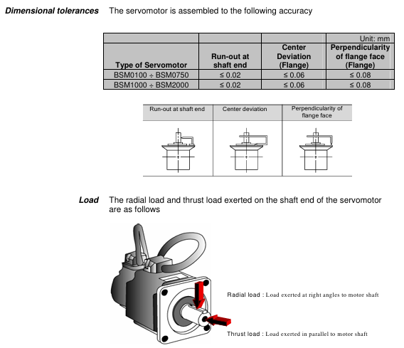
The installation direction can be horizontal, downward, or upward (in accordance with IEC standards IMB5/L51, etc.), and the encoder end should not be subjected to force
Load limit radial load (127N-510N), axial load (19N-253N) refer to Table 2-5 in the document, such as BSM0100 radial 127N
Cable protection for mobile scenarios requires drag chains with a maximum bending radius to avoid oil/water immersion
2. Installation of servo amplifier
Project Requirements Remarks
Storage environment temperature -20 ° C~85 ° C, humidity 10% -90% RH (no condensation), altitude ≤ 1000m, no dust/corrosive gas
Working environment temperature -10 ° C~55 ° C, humidity 10% -90% RH (no condensation), non drip/dust-proof, multiple installations require spacing
Installation direction Upright direction (horizontal marked with "BSD") Heat dissipation requirements
When the installation spacing is ≥ 50mm at the top and ≥ 40mm at the bottom, and the spacing between multiple parallel units is ≥ 5mm and < 5mm, the rating needs to be reduced to 80% ED
Leave ≥ 70mm (for easy operation) for wiring in the front space, with a depth of 165mm for 1.0kW and below, and 185mm for 1.5kW and above
Wiring specifications
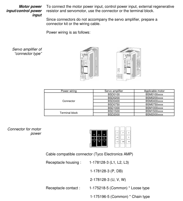
1. Power wiring
Equipment power type, wiring terminal voltage range, frequency
Servo amplifier (0.4kW and below) single-phase L1, L2 200-230VAC (-10%~+10%) 50/60Hz
Servo amplifier (0.75kW) single-phase/three-phase L1, L2 (single-phase); L1, L2, L3 (three-phase) 200-230VAC (single-phase -10%~+10%, three-phase -15%~+10%) 50/60Hz
Servo amplifier (0.85kW and above) three-phase L1, L2, L3 200-230VAC (-15%~+10%) 50/60Hz
Control power supply (all models) single-phase sL1, sL2 200-230VAC (-10%~+10%) 50/60Hz
2. Key wiring taboos
Do not connect the commercial power supply (200V) to the U/V/W terminals of the servo motor (as it may burn the motor).
Do not connect the grounding wire (E) to the U/V/W terminal, and do not connect the U/V/W terminal in reverse (which may cause fire/malfunction).
It is prohibited to conduct voltage withstand, megaohm, and buzzing tests on the encoder terminal (CN2) as it may damage the encoder.
The distance between the serial I/O (CN1) and the motor power cable should be ≥ 10cm (to avoid interference).
Test Run
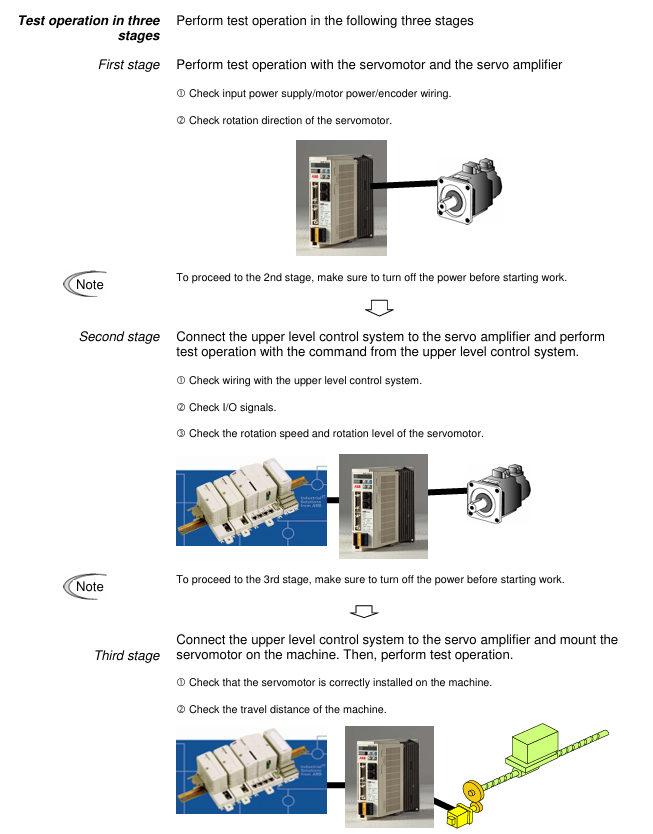
1. Three stage testing process
Key inspection items for stage testing content
The first stage servo amplifier and motor are tested separately (not connected to the machine). 1. Power wiring (L1/L2/L3); 2. Motor power supply (U/V/W) and encoder wiring; 3. Motor rotation direction (parameter # 04); 4. No alarm
In the second stage, connect to the upper control system (not connected to the machine). 1. Connect the signal lines of the upper system; 2. I/O signals (such as emergency stop EMG, overtravel ± OT); 3. Motor speed/torque (in accordance with instructions)
The third stage of testing after installing the machine (final state): 1. The firmness of the motor installation; 2. Machine travel; 3. Servo parameter adjustment (refer to Chapter 6); 4. Positioning accuracy
2. Origin regression requirements
After power failure and restart, the motor needs to be rotated at a speed of ≤ 100r/min for 372 ° or more (approximately 1.04 rpm) in order to correctly detect the Z-phase.
Parameter settings
1. Parameter configuration method
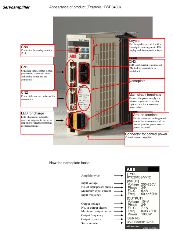
Keyboard operation: Switch to "Parameter Editing Mode" (PnO) for settings through a 4-digit 7-segment LED display and 4 buttons (MODE/ESC, SHIFT, ENT, ∧/∨).
BSD Configurator: Connected to CN3 via LAN cable (CAT. 5 direct connection), supports parameter read/write, batch transfer, and monitoring.
2. Core parameter table
Parameter number, parameter name, control mode, setting range, initial value, key role
#01 Command pulse compensation alpha position 1-32767 16 electronic gear ratio molecule, converting command pulse to mechanical stroke
#02 instruction pulse compensation β position 1-32767 1 electronic gear ratio denominator
#03 Pulse train input form: Position 0 (command pulse+symbol), 1 (forward/reverse pulse), 2 (two signals with a 90 ° phase difference), 1 matches the output type of the upper system pulse
#04 Rotation direction switching/output pulse phase all 0-30 set motor forward rotation direction (CCW/CW) and output pulse phase
#05 tuning mode position/speed 0 (automatic), 1 (semi-automatic), 2 (manual) 0 select servo gain tuning mode
#06 Load inertia ratio position/velocity GYS: 0.0-100.0; GYG: 0.0-30.0 5.0 (BSM low power), 1.0 (BSM high power) ratio of motor inertia to load inertia
#07 Automatic tuning gain position/speed 1-20 10 Adjust servo response speed (high value, fast response but prone to vibration)
#09 Control mode switch all 0 (position), 1 (speed), 2 (torque), 3 (position) ↔ 0 fixed or switchable control mode for speed)
3. Parameter Effectiveness Rules
The parameters marked as "Power" (such as # 03, # 04, # 09) need to be powered off and restarted to take effect; Other parameters (such as # 01, # 02, # 07) take effect in real-time.
Servo adjustment and special functions
1. Tuning method
Operation points for applicable scenarios of tuning types
Automatic tuning (# 05=0) Most conventional mechanical amplifiers automatically estimate the inertia ratio and set the optimal gain
Semi automatic tuning (# 05=1) inaccurate estimation of inertia ratio, manual setting of # 06 (load inertia ratio) in scenarios, amplifier automatically calculates gain
Manual tuning (# 05=2) Automatic/semi-automatic tuning failed. Manually set # 40 (position gain), # 41 (speed response), # 42 (speed integration time), etc
2. Special adjustment function
Vibration suppression control: By setting parameters # 60- # 63 (anti resonance frequency 0-3), mechanical vibrations (such as end effector vibrations of robotic arms) are suppressed within a frequency range of 5.0-200.0Hz.
Instruction Follow Control: Parameter # 55 is set (0=none, 1=follow, 2=follow+stop compensation) to achieve zero deviation following of pulse instructions, suitable for high rigidity machinery.
Inspection and maintenance
1. Regular inspection items
Equipment inspection content inspection frequency
Servo motor 1. Mechanical coupling deviation; 2. Smoothness of axis rotation; 3. Cable damage; 4. Loosening of screws regularly (e.g. monthly)
Servo amplifier 1. Dust accumulation; 2. Abnormal noise from the cooling fan; 3. Loose terminal screws; 4. No odor/signs of overheating regularly (e.g. monthly)
2. Service life and replacement of vulnerable parts
Component Standard Life Replacement Tips
Servo amplifier main circuit capacitor 73000h (10 years), lifespan shortened when ambient temperature exceeds 30 ° C
Replace the servo amplifier cooling fan when it makes abnormal noise or stops running after 30000 hours (3 years)
Replace servo motor bearings when vibration/abnormal noise occurs after 20000-30000 hours (3-5 years)
Replace the servo motor oil seal after 5000 hours of oil leakage
3. Common alarm handling
Alarm code, alarm reason, handling measures
OC1/OC2 overcurrent 1. Check the U/V/W wiring of the motor; 2. Check if the motor is short circuited/grounded; 3. Replace the amplifier
OL overload 1. Check motor load matching; 2. Extend the acceleration and deceleration time; 3. Reduce operating frequency
HV overvoltage 1. Check the power supply voltage; 2. Connect external regenerative resistors; 3. Extend deceleration time
LV undervoltage 1. Check the power supply voltage; 2. Confirm parameter # 26 (undervoltage detection) setting; 3. Improve the power environment
RS485 communication
1. Communication specifications
Project specifications
Signal level RS485
Communication method: 4-wire half duplex, asynchronous communication
Baud rate 9600/19200/38400bps (parameter # 83 setting)
Data format: 1 start bit, 8 data bits, 1 even check bit, 1 stop bit
Station number 1-31 (parameter # 2 setting)
Connect cable LAN line (CAT. 5 direct connection)
2. Core functions
Read: Multiple monitoring data (such as speed, torque), sequence mode, I/O signals, alarm history, system status.
Write: parameters, alarm reset, parameter initialization.
- YOKOGAWA
- Reliance
- ADVANCED
- SEW
- ProSoft
- WATLOW
- Kongsberg
- FANUC
- VSD
- DCS
- PLC
- man-machine
- Covid-19
- Energy and Gender
- Energy Access
- Renewable Integration
- Energy Subsidies
- Energy and Water
- Net zero emission
- Energy Security
- Critical Minerals
- A-B
- petroleum
- Mine scale
- Sewage treatment
- cement
- architecture
- Industrial information
- New energy
- Automobile market
- electricity
- Construction site
- HIMA
- ABB
- Rockwell
- Schneider Modicon
- Siemens
- xYCOM
- Yaskawa
- Woodward
- BOSCH Rexroth
- MOOG
- General Electric
- American NI
- Rolls-Royce
- CTI
- Honeywell
- EMERSON
- MAN
- GE
- TRICONEX
- Control Wave
- ALSTOM
- AMAT
- STUDER
- KONGSBERG
- MOTOROLA
- DANAHER MOTION
- Bentley
- Galil
- EATON
- MOLEX
- Triconex
- DEIF
- B&W
- ZYGO
- Aerotech
- DANFOSS
- KOLLMORGEN
- Beijer
- Endress+Hauser
- schneider
- Foxboro
- KB
- REXROTH
- YAMAHA
- Johnson
- Westinghouse
- WAGO
- TOSHIBA
- TEKTRONIX
- BENDER
- BMCM
- SMC
- HITACHI
- HIRSCHMANN
- XP POWER
- Baldor
- Meggitt
- SHINKAWA
- Other Brands
- UniOP
- KUKA
- IBA
- Beckhoff
-
ADLINK CPCI-6860A - 51-31310-OB10 industrial motherboard CompactPCI SBC
-
ADLINK AmITX-SL-G-H110 - 51-7A104-0A30 Mini-ITX Industrial Motherboard
-
ADLINK PXI-2005-003 - CPCI Industrial PC Data Acquisition Card Multi-Function DAQ
-
ADLINK DININ-814M - 51-14032-0A3D SCSI-100P cable connection Interface Terminal Board
-
ADLINK CPCI-3920NA/C2D15/M1G - 3U CompactPCI Intel Core 2 Duo Single Board Computer
-
ADLINK PCIE-8560 - 51-18014-0A20 Communication Card High Speed DAQ
-
ADLINK PCI-C154+ - Motion Control Card 4-axis Motion Controller Board
-
ADLINK PCI-RTV24 - image capture card Analog Video Frame Grabber
-
ADLINK NuPRO-842LV/P - 51-41360-0B30 Industrial Motherboard CPU Board
-
ADLINK cBP-3208/3208R - CPCI Board 3U 8-Slot CompactPCI Backplane
-
ADLINK PCI-8164 - 4-Axis Motion Controller PCI Card 51-12406-0A40
-
ADLINK PCIe-GIE64+ - 4-CH GigE Vision PoE+ Frame Grabber Video Capture Card
-
ADLINK CPCI-6860 / 6860A - CompactPCI Dual Xeon Single Board Computer
-
ADLINK IEC-915GV - REV 1.1 Industrial motherboard CPU Board
-
ADLINK ND-6520 - Technology RS-232 to RS-422RS-485 Converter NuDAM Module
-
ADLINK RTV-24 / PCI-MP4S - 51-12519-1C30 4-Channel Real Time Video Capture Board
-
ADLINK cPCI-6910 / cPCI-6910AM/M1G - cPCI-6910AM/DXL16/M1G/S80G(G)-3120 BOARD CompactPCI SBC
-
ADLINK NUPRO-A40H - Linghua 51-41807-1A30 Industrial Control Computer Motherboard
-
ADLINK USB-3488A - USB to GPIB INTERFACE USB-3488A(G) Controller Module
-
ADLINK PCI-8134A - motion control card 4-Axis Controller Card
-
ADLINK PCI-7432 - Board 32-Channel input / 32-output Isolated Digital I/O PCI Card
-
ADLINK PCI-8134A - 51-12421-0A10 motion controller card tested
-
ADLINK LPCIe-7230 - 32 CH Isolated Input/output Card 2 Interrupts Low Profile PCIe
-
ADLINK NuPRO-E340 - industrial computer motherboard 51-47807-0A30 PICMG 1.3 SHB
-
ADLINK PCI-7434 - High-speed Digital Acquisition Card 64-CH Isolated DO Card
-
ADLINK NuPRO-E330 - 51-41805-0A20 Indsutrial Board SHB Single Board Computer
-
ADLINK PCI-7248 - OPTO-22 48 CHANNEL DIO DIGITAL TTL/DTL I/O 51-12006-0A40 GP
-
ADLINK PCI-8134 - Motion control card 4-Axis Controller Card
-
ADLINK AMP-208C - Movimiento Control Tarjeta 51-12420-1A20 W/Expansión & Breakout
-
ADLINK PCI-8164 - 51-12406-0A40 PCB Board 4-Axis Motion Controller Card
-
ADLINK DIN-68Y-SGII / DIN-68M-J3A - Terminal Board Connector Interface Block
-
ADLINK PCIe-7432 - Technology 51-18402-0A10 PCIe Card With High Input Range
-
ADLINK PCI-8144 / PCI-8144N - Motion control card 4-Axis Stepper Controller Card
-
ADLINK HSL-HUB3/REPEATER - HIGH SPEED LINK EXTENSION MODULES Distributed Hub Module
-
ADLINK ND-6017 - Data Logging + Acquisition 8CH A/D input Mod NuDAM Module
-
ADLINK LPCIe-7250 - data acquisition card Low Profile 8-CH Relay Output Card
-
ADLINK PCI-7432 - I/O card 64-CH Isolated Digital Input Output PCI Card
-
ADLINK IMB-M43H - industrial control computer motherboard Q87 Chip Micro-ATX
-
ADLINK MP-C154 - Motion control Card 4-Axis Motion Controller Board
-
ADLINK PCI-RTV24 - image capture card Video Frame Grabber Card
-
ADLINK PCI-7250 - 8-CH Relay Output & 8-CH Isolated DI Card
-
ADLINK PCI-6308V - 8-CH 12-Bit Isolated Analog Output PCI Card PCB-I-E-1148=6EX2
-
ADLINK PCI-7248 - capture card 48-CH Opto-22 Compatible DIO Card
-
ADLINK HSL-AI16A02-M-VV - Analog Input Output Distributed Module
-
ADLINK NuPRO-A301 - Rev:1.4 NUPRO-A301 PICMG Full-Size Single Board Computer
-
ADLINK PCI-6208V-GL - 8-CH Voltage Analog Output PCI Card
-
ADLINK PCI-8134A - 51-12421-0A10 4-Axis Motion Controller Card
-
ADLINK MNET-S23 - TECHNOLOGY MNET S23 - SERVO DRIVER CONTROL MODULE
-
ADLINK M-342 - ATX I3 I5 I7 Q67 Industrial Motherboard
-
ADLINK NUPRO-780 - Industrial Motherboard CPU Board PICMG SBC
-
ADLINK MP-C154 / MP-C152 - 4-Axis Motion Control Card Pulse-Train Controller
-
ADLINK NuPRO-935A/LV10B0 - Motherboard 51-41802-0A10 GP w/RAM Industrial Control Board
-
ADLINK MP-C154 - Motion control card 4-Axis Motion Controller Mainboard
-
ADLINK PCI-7250 - PCI Acquisition Card 8-CH Relay Output Isolated DI Card
-
ADLINK ACL-7124 - Technology Inc.24 DIO Card Digital Input Output Card
-
ADLINK PCI-8554 A2 - Timer/Counter Data Acquisition Card
-
ADLINK DIN-825-GP4 - Terminal Block Interface Board Breakout Module
-
ADLINK NuPR0-761 - REV:1.1 Industrial motherboard Full-Size PICMG SBC
-
ADLINK MXE-1401/M8G (G) - Matrix Fanless Embedded Computer Industrial PC
-
ADLINK HSL-DI16DO16-UD-NN - Digital 16 Channel I/O Mod Distributed I/O Module
-
ADLINK ND6520 - NUDAM INTELLIGENT DA&C MODULE RS232-RS-422/RS485 CONVERTOR
-
ADLINK NUPRO-761 - REV:1.1 Industrial Motherboard CPU Board
-
ADLINK AMP-208C - Motion Control Card 51-12420-1A20 DSP-based 8-axis
-
ADLINK NuPRO-A301REV 1.4 - with packaging industrial computer motherboard PICMG SBC
-
ADLINK PCM-9112+ - 51-12300-0A2 industrial motherboard Multi-Function DAQ PC/104 Module
-
ADLINK PCM-7250+ - 8-CH Relay Outputs & 8-CH Isolated DI Module PC/104
-
ADLINK PCI-RTV24 - Image capture card Analog Video Frame Grabber
-
ADLINK PCI-8134 - Motion Controller PCI Card 4-Axis Controller Board
-
ADLINK PCI-7432 - Isolated Digital I/O PCI Card
-
ADLINK PCI-8554 A2 - acquisition card Timer/Counter Card
-
ADLINK PCI-8132 - Rev.A2 2-Axis Servo & Stepper Motion Controller Card
-
ADLINK PCI-8132 - Data Acquisition card 2-Axis Motion Controller Card
-
ADLINK EBP-13E4 - 51-46703-0A30 Industrial Backplane Board Passive Backplane
-
ADLINK PCI-800L - Electronic Card Interface Controller Card
-
ADLINK PCIe-GIE72 - 51-18531-0A10 PCB Board GigE Vision Frame Grabber
-
ADLINK DAQ-2010(G)-OOBO - Simultaneous-Sampling Multi-Function DAQ Card
-
ADLINK PCI-9112 - REV.B1 Multifunction DAQ Card Data Acquisition Card
-
ADLINK PCI-7230 - 51-12003-DA60 32-CH Isolated Digital I/O Card
-
ADLINK PCI-7432 - Data Acquisition Card Isolated Digital I/O PCI Card
-
ADLINK ETX-AT-N270-18/LXE - 51-71111-0A20 ETX CPU Module Motherboard
-
ADLINK HSL-DI32-UD-N - DIGITAL INPUT 32 POINTS MODULE Distributed I/O
-
ADLINK AMP-204C - Motion Control card DSP-Based 4-Axis Advanced Controller
-
ADLINK MNET-4XMOG-0050 - Four-axis Motion Controller Distributed Motion Module
-
ADLINK AMP-204C - Motion control card DSP-Based 4-Axis Pulse-Train Controller
-
ADLINK PCI-7442 - Switch card 64-Channel Datalogging & Acquisition Card
-
ADLINK M-302 - Industrial control motherboard ATX PC Board
-
ADLINK NUPRO-852 / NUPRO-852LV - Industrial motherboard Single Board Computer
-
ADLINK PCI-8134 - REV.B1. 4-Axis Motion Controller Card
-
ADLINK PCI-GIE62 + - 51-18502-0A20 2-CH GigE Vision Frame Grabber PoE Card
-
ADLINK PCI-MPG24 - 51-12523-0B20 MPEG4 Card Video Compression Hardware
-
ADLINK HSL-TB32-M-DIN - 32-CH I/O TERMINAL W/ HSL-AI16AO2-M-VV MODULE
-
ADLINK PCI-M114-GL - PCB Ver 2.1 Motion Controller Axis Card
-
ADLINK IMB-M40H - SYM76996H61 motherboard Industrial Computer Mainboard
-
ADLINK NUPRO-A40H - 51-41807-1A20 industrial control motherboard H61 Chip
-
ADLINK PCI-M114-GL - Axis Card Data Acquisition Card PCB VER2.2 Motion Controller
-
ADLINK PCI-8134 - Motion Controller PCI Card 4-Axis Controller Board
-
ADLINK PCI-8102 - Motion control card 2-Axis Servo & Stepper Controller
-
ADLINK NuPRO-841REV:3.0 - motherboard Industrial Control PC Board
-
ADLINK HSL-TB32-U-DIN REV A1 - Breakout Terminal Board Field I/O Module
-
ADLINK AMP-204C - Motion Control card DSP-Based 4-Axis Pulse-Train Controller
-
ADLINK NUPRO-A40H - 51-41807-1A20 industrial control motherboard H61 PC Board
-
ADLINK PCI-6308A / PCI-6308V - 51-12202-0A50 Isolated Analog Output Card
-
ADLINK AMP-204C - DSP-Based 4-Axis Advanced Pulse-Train Motion Controller
-
ADLINK PCI-7434 - Technology 64-Channel Isolated Digital I/O PCI Cards
-
ADLINK CPCI-6840 / CPCI-6840V / PM16/M1G-12G0 - CompactPCI Single Board Computer CPU Module
-
ADLINK PCIE-GIE74 - Motherboard Video Capture Card 51-18531-0A10 Frame Grabber
-
ADLINK NuPRO-E330 - industrial computer equipment motherboard Control Mainboard
-
ADLINK AMP-208C / 51-12420-1A20 - Motion Control Card W/ Expansion & Breakout Board
-
ADLINK HPCI-14S12U - industrial computer baseboard Passive Backplane 14 Slots
-
ADLINK PCI-8164 - 4-Axis Motion Controller PCI Card W/ 1x Cable, 1x Breakout Box
-
ADLINK PCIe-RTV24 - 51-18016-0A20 Image Acquisition Video Capture Card
-
ADLINK M-342 - 5 PCI ATX Motherboard Industrial PC Mainboard
-
ADLINK PCI-FIW64 - 4/2 Channel IEEE1394B Image Capture Card FireWire Frame Grabber
-
ADLINK PCI-7432 - digital IO card 64-CH Isolated Digital Input Output Card
-
ADLINK 51-12001-0C20 - Circuit Board PCI-7200 Data Acquisition Controller Card
-
ADLINK PXI-3920 - PXI 3U cPCI Industrial Controller Embedded System CPU Board
-
ADLINK NuPRO-841REV:2.0 - motherboard Industrial Control PC Board
-
ADLINK NuPro-E330 - 51-41805-0A20 PCB Industrial Control Computer Motherboard
-
ADLINK PCI-RTV24 - Image capture card Analog Video Frame Grabber
-
ADLINK PCI-7442 - Switch card 64-Channel Datalogging & Acquisition Card
-
ADLINK HPX-13S4 - device baseboard Passive Backplane Riser Card
-
ADLINK PCI-9112 REV A.1 - Multi Function DA&C Board Data Acquisition Card
-
ADLINK PCI-7248 - 51-12006-0A40 Card Control 48-CH Digital I/O Module
-
ADLINK CPCI-6860 / 6860A - motherboard CompactPCI Dual Xeon Single Board Computer
-
ADLINK DPAC-3020-11(G) - Embedded PC Automation Controller Machine Control Board
-
ADLINK NuPRO-841 REV:1.0 - industrial control motherboard CPU Board
-
ADLINK MNET-4XMOG-0050 - Four-axis Motion Controller MNET Motion Control Card
-
ADLINK ETX-AT-N270-18/LXE - 51-71111-0A20 ETX CPU Module Motherboard

K-JIANG

Add: Jimei North Road, Jimei District, Xiamen, Fujian, China
Tell:+86-15305925923