
K-WANG


TOSHIBA VF-S15 frequency converter
Example of input voltage level frequency converter model
Single phase 200V-240V VFS52S-2002PL__/- W1/Y-A *, VFS52S-2004PL__/- W1/Y-A*
Three phase 200V-240V VFS15-2002PM_/- W1/Y-A *, VFS15-2004PM_/- W1/Y-A*
Three phase 380V-500V VFS15-4004PL_/- W1/Y-A *, VFS15-4007PL_/- W1/Y-A*
Three phase 525V-600V VFS15-6015P_/- W1/Y-A *, VFS15-6022P_/- W1/Y-A*
TOSHIBA VF-S15 frequency converter
Basic information of the document
Scope of Application
The document specifically lists the applicable models (including multiple voltage levels) for the Toshiba VF-S15 series frequency converter, as shown in the table below. Models marked with suffixes such as "Y-A38" and "Y-A65" are not applicable.
Example of input voltage level frequency converter model
Single phase 200V-240V VFS52S-2002PL__/- W1/Y-A *, VFS52S-2004PL__/- W1/Y-A*
Three phase 200V-240V VFS15-2002PM_/- W1/Y-A *, VFS15-2004PM_/- W1/Y-A*
Three phase 380V-500V VFS15-4004PL_/- W1/Y-A *, VFS15-4007PL_/- W1/Y-A*
Three phase 525V-600V VFS15-6015P_/- W1/Y-A *, VFS15-6022P_/- W1/Y-A*
Safety warnings and personnel qualifications
1. Warning system
The document categorizes safety warnings into two types, specifying risk levels and response requirements:
Warning type meaning Typical scenarios
Warning operation errors may result in death or serious injury. Touching live cables, repairing without discharge, and short circuiting DC bus capacitors
Incorrect operation of the solution may result in minor injuries or equipment damage, voltage incompatibility, capacitor aging, and performance degradation
2. Core security taboos (Warning level)
Do not touch live cables (such as printed circuit boards) inside the frequency converter, and use insulated tools;
Before maintenance, it is necessary to follow the process of "power off → paste the prohibition closing label → lock the power-off switch → wait for 15 minutes to discharge → measure the DC bus voltage<42V";
Do not short-circuit PA/+and PC/- terminals or DC bus capacitors;
Before powering on, all cover plates must be installed and closed.
3. Personnel qualification requirements
Only qualified personnel are allowed to operate (subject to the following conditions):
Having received safety training, able to identify and mitigate risks;
Familiar with this manual and product documentation, proficient in electrical/mechanical system knowledge;
Understand international/national electrical codes and accident prevention regulations.
Detailed explanation of core security functions
1. STO (Safe Torque Off)
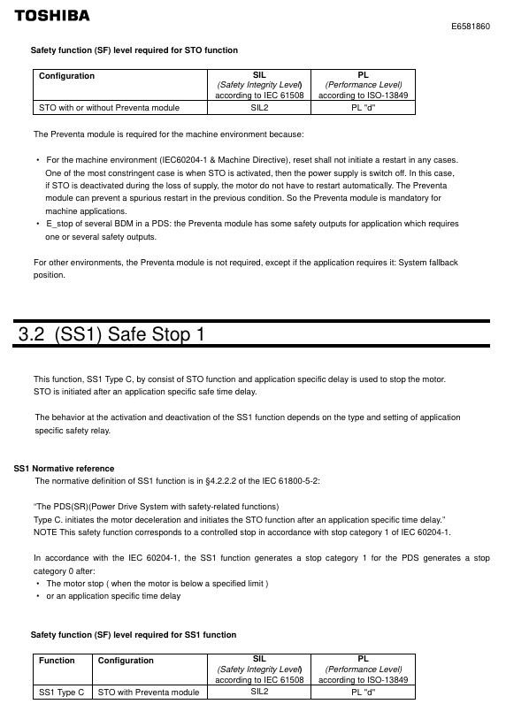
Function definition: To put the motor into a torque free state (prohibiting motor start or free stop), cut off the energy supply to the motor, corresponding to IEC 60204-1 stop category 0 (uncontrolled stop).
**According to * *: IEC 61800-5-2 § 4.2.2.2, it should be noted that additional mechanical brakes are required for suspended load scenarios, and electronic components cannot replace anti electric shock isolation measures.
Security level:
Configuration method SIL (IEC 61508) PL (ISO 13849-1) EN 954-1 category
With/without Preventa module SIL 2 PL d 3
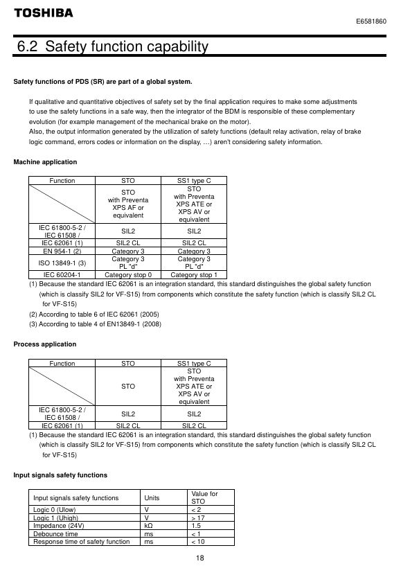
Key parameters: response time<10ms, logic input 0<2V, 1>17V, impedance 1.5k Ω.
Module requirements: Mechanical applications (compliant with IEC 60204-1) require mandatory use of Preventa modules (such as XPS AF) to prevent accidental restarts; Use as needed in other scenarios.
2. SS1 (Safe Stop 1, Safety Stop Class 1, Type C)
Function definition: First, slow down the motor according to the specified time delay. After the delay ends, trigger the STO function, corresponding to IEC 60204-1 stop category 1 (control stop).
Normative basis: IEC 61800-5-2 § 4.2.2.2, requires the use of specific safety relays to implement delay logic.
Security level:
Configuration method SIL (IEC 61508) PL (ISO 13849-1) EN 954-1 category
STO+Previnta module (such as XPS AV) SIL 2 PL d 3
Application logic: The deceleration delay time needs to be set according to the actual scenario, and the motor will enter a torque free state after the delay ends.
Compliance standards and safety performance
1. Follow the standards
Specific core requirements for standard categories
IEC 61800 series variable speed electric drive system safety requirements for drive systems
Functional Safety IEC 61508 Ed.2 Electrical/Electronic/Programmable Systems Functional Safety, Defining SIL Levels
Mechanical safety ISO 13849-1/2, EN 954-1 Safety components of mechanical control systems, defining PL levels and categories
Process Safety IEC 62061 Process Industry Safety Instrumented Systems, Distinguishing Global/Component SIL
2. Safety performance indicators
Taking the STO function as an example, the key performance parameters are shown in the following table:
Explanation of Indicator Values
SFF (Safety Failure Score) 96.7% represents the proportion of safety failures to total failures, reflecting the safety of the system
MTTFd (Mean Time to Failure) is the average interval between system failures in the year 16200
PFHequ_1y (annual hazard failure probability) 7.04 FIT 1FIT=10 ⁻⁹ times/hour, which means the annual failure probability is extremely low
HFT (Hardware Fault Tolerance) 1 allows one hardware fault to maintain safety functionality
Equipment type B complies with the definition of Class B subsystems in IEC 61508
System architecture and application limitations
1. Authentication architecture (3 types)
The document provides three certified security system architectures, adapted to different application scenarios:
Architecture Type Applicable Scenarios Core Configuration Compliance Standards
Case 1 Mechanical Applications - STO VF-S15+Preventa XPS AF Module EN 954-1, ISO 13849-1, IEC 60204-1
Case 2 Mechanical Applications - SS1 VF-S15+Preventa XPS AV Module EN 954-1, ISO 13849-1, IEC 60204-1
Case 3 Process Application - STO VF-S15 (without additional modules) IEC 61508 (SIL 2/SIL 1)
2. Application restrictions
Prohibited scenarios: Applications where the load may accelerate after shutdown (such as vertical conveyors, elevators, and winches) pose safety hazards;
Function priority: STO has the highest priority. If STO is triggered, no torque operation will be executed first regardless of whether other functions are activated or not;
Prerequisite: The motor/frequency converter needs to be matched with the application capacity, and the speed loop and torque characteristics should be correctly configured. If necessary, dynamic braking resistors and other options should be provided.
Maintenance and compliance documents
1. Maintenance requirements
Preventive maintenance: It is recommended to check the safety function once a year (such as opening the protective door to verify whether the frequency converter stops according to the set safety function);
Component replacement: After replacing non VF-S15 components such as motors and emergency stop switches, acceptance testing must be performed again;
Capacitor maintenance: For products stored for more than 2 years, the capacitor needs to be gradually boosted and activated through a variable power supply (25% → 50% → 75% → 100% rated voltage, each for 30 minutes) before use.
2. Compliance documents
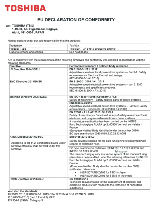
EU Declaration of Conformity: covering ATEX Directive, Machinery Directive, EMC Directive, to be executed in conjunction with the ATEX Guidelines and Safety Guidelines accompanying the product;
Declaration signing: Signed by both Technical Document Manager (Fredric Roussel, France) and Marketing Manager (Shin Okada, Japan), released in 2019;
Option compliance: Communication options (such as CANopen, PROFINET) and power options (such as EMC filters) require the use of original factory certified accessories (refer to the appendix options list).
Key issues
Question 1: Why is it necessary to use Preventa module for the STO function of VF-S15 frequency converter in mechanical applications? What is its core function?
Answer: Mechanical applications (compliant with IEC 60204-1 and the Machinery Directive) mandate the use of Preventa modules (such as XPS AF), with the following core reasons and functions:
Prevent accidental restart: If there is a power outage after the STO is activated, and the STO is mistakenly released during the power outage, the motor may automatically restart after the Preventa module is restored, posing a safety risk; The Preventa module can intercept this false trigger and ensure that manual operation is required to restart after power restoration, meeting the mechanical safety requirements of "reset does not trigger automatic start";
Multi device emergency stop coordination: If the system contains multiple BDMs (background debugging modules), the Preventa module provides multiple safety output interfaces, which can achieve synchronous emergency stop control of multiple devices and meet the safety linkage requirements of complex mechanical systems;
Compliance guarantee: Only with the Preventa module can the STO function fully comply with the requirements of EN 954-1 category 3 and ISO 13849-1 PL d, ensuring that mechanical applications pass safety certification.
(Note: For non mechanical scenarios such as process applications, if there is no need to prevent accidental restarts or multi device collaboration, the Preventa module is not necessary.). )
Question 2: What is the core difference between the SS1 function (Safety Stop Class 1 Type C) of VF-S15 and the STO function? How to choose which function to use in practical applications?
Answer: The core differences and application selection logic between the two are as follows:
1、 Core difference
Comparison Dimension STO (Safe Torque Off) SS1 (Safe Stop Class 1, Type C)
The functional logic directly cuts off the motor torque, and the motor stops freely. First, it decelerates according to the set time, and then triggers STO after a delay
Stop category (IEC 60204-1) Category 0 (uncontrolled stop, fast but no deceleration) Category 1 (controlled stop, with deceleration process)
Applicable scenarios require emergency torque cut-off (such as personnel entering a dangerous area by mistake) and require smooth deceleration to avoid load impact (such as transporting fragile items)
Module dependent mechanical applications require Preventa modules, while other scenarios require the use of Preventa modules (such as XPS AV) to implement delay logic as needed
2、 Application selection principle
Select STO: When the scenario requires "immediately cutting off torque to avoid emergency risks" (such as operators accidentally touching dangerous areas or equipment operating abnormally), prioritize using STO to ensure that the motor quickly enters a torque free state;
Select SS1: When the scenario requires "smooth shutdown to protect the load or equipment" (such as conveying glass, precision parts, or avoiding mechanical impact during shutdown), use SS1 to achieve controlled shutdown through delayed deceleration and reduce the risk of load damage.
Question 3: According to the IEC 61508 standard, what does SIL 2 level mean for the STO function of VF-S15 frequency converters? How do its key performance indicators support the requirements of this level?
Answer: The meaning of SIL 2 level and the performance support of VF-S15 are as follows:
1、 The meaning of SIL 2 level (IEC 61508 Ed.2)
SIL (Safety Integrity Level) is an indicator that measures the ability of safety functions to resist dangerous failures. SIL 2 represents:
In high demand or continuous operation mode, the annual probability of failure (PFH) of safety functions must meet the requirement of 10 ⁻⁷ ≤ PFH<10 ⁻⁶;
Suitable for scenarios where dangerous events may cause serious injuries but have a low probability of occurrence, such as personnel protection for industrial machinery and overload protection for process equipment.
2、 Performance support for VF-S15 STO function
The STO function meets SIL 2 requirements through the following key indicators:
PFH index: The measured PFHequ_1y (annual equivalent hazard failure probability) is 7.04 FIT (1 FIT=10 ⁻⁹ times/hour), which is equivalent to an annual PFH of approximately 7.04 × 8760 × 10 ⁻⁹ ≈ 6.17 × 10 ⁻⁵? No, the document clearly states "PFHequ_1y=7.04 FIT", combined with SFF=96.7% (high proportion of safety failures), the actual probability of dangerous failure is in the range of 10 ⁻⁷~10 ⁻⁶, which complies with SIL 2;
Hardware Fault Tolerance (HFT): HFT=1, which allows the STO function to still execute normally in the event of one hardware fault (such as a single input signal failure), meeting the hardware fault tolerance requirements of SIL 2;
Safety Failure Factor (SFF): SFF=96.7%, much higher than the minimum SFF requirement of IEC 61508 for SIL 2 (60%), indicating that most system failures are safety failures and the proportion of hazardous failures is extremely low;
Mean Time to Failure (MTTFd): MTTFd=16200 years, reflecting the extremely long interval of hazardous failures during long-term system operation, further verifying the stability of SIL 2.
- YOKOGAWA
- Reliance
- ADVANCED
- SEW
- ProSoft
- WATLOW
- Kongsberg
- FANUC
- VSD
- DCS
- PLC
- man-machine
- Covid-19
- Energy and Gender
- Energy Access
- Renewable Integration
- Energy Subsidies
- Energy and Water
- Net zero emission
- Energy Security
- Critical Minerals
- A-B
- petroleum
- Mine scale
- Sewage treatment
- cement
- architecture
- Industrial information
- New energy
- Automobile market
- electricity
- Construction site
- HIMA
- ABB
- Rockwell
- Schneider Modicon
- Siemens
- xYCOM
- Yaskawa
- Woodward
- BOSCH Rexroth
- MOOG
- General Electric
- American NI
- Rolls-Royce
- CTI
- Honeywell
- EMERSON
- MAN
- GE
- TRICONEX
- Control Wave
- ALSTOM
- AMAT
- STUDER
- KONGSBERG
- MOTOROLA
- DANAHER MOTION
- Bentley
- Galil
- EATON
- MOLEX
- Triconex
- DEIF
- B&W
- ZYGO
- Aerotech
- DANFOSS
- KOLLMORGEN
- Beijer
- Endress+Hauser
- schneider
- Foxboro
- KB
- REXROTH
- YAMAHA
- Johnson
- Westinghouse
- WAGO
- TOSHIBA
- TEKTRONIX
- BENDER
- BMCM
- SMC
- HITACHI
- HIRSCHMANN
- XP POWER
- Baldor
- Meggitt
- SHINKAWA
- Other Brands
- UniOP
- KUKA
- IBA
- Beckhoff
-
ADLINK CPCI-6860A - 51-31310-OB10 industrial motherboard CompactPCI SBC
-
ADLINK AmITX-SL-G-H110 - 51-7A104-0A30 Mini-ITX Industrial Motherboard
-
ADLINK PXI-2005-003 - CPCI Industrial PC Data Acquisition Card Multi-Function DAQ
-
ADLINK DININ-814M - 51-14032-0A3D SCSI-100P cable connection Interface Terminal Board
-
ADLINK CPCI-3920NA/C2D15/M1G - 3U CompactPCI Intel Core 2 Duo Single Board Computer
-
ADLINK PCIE-8560 - 51-18014-0A20 Communication Card High Speed DAQ
-
ADLINK PCI-C154+ - Motion Control Card 4-axis Motion Controller Board
-
ADLINK PCI-RTV24 - image capture card Analog Video Frame Grabber
-
ADLINK NuPRO-842LV/P - 51-41360-0B30 Industrial Motherboard CPU Board
-
ADLINK cBP-3208/3208R - CPCI Board 3U 8-Slot CompactPCI Backplane
-
ADLINK PCI-8164 - 4-Axis Motion Controller PCI Card 51-12406-0A40
-
ADLINK PCIe-GIE64+ - 4-CH GigE Vision PoE+ Frame Grabber Video Capture Card
-
ADLINK CPCI-6860 / 6860A - CompactPCI Dual Xeon Single Board Computer
-
ADLINK IEC-915GV - REV 1.1 Industrial motherboard CPU Board
-
ADLINK ND-6520 - Technology RS-232 to RS-422RS-485 Converter NuDAM Module
-
ADLINK RTV-24 / PCI-MP4S - 51-12519-1C30 4-Channel Real Time Video Capture Board
-
ADLINK cPCI-6910 / cPCI-6910AM/M1G - cPCI-6910AM/DXL16/M1G/S80G(G)-3120 BOARD CompactPCI SBC
-
ADLINK NUPRO-A40H - Linghua 51-41807-1A30 Industrial Control Computer Motherboard
-
ADLINK USB-3488A - USB to GPIB INTERFACE USB-3488A(G) Controller Module
-
ADLINK PCI-8134A - motion control card 4-Axis Controller Card
-
ADLINK PCI-7432 - Board 32-Channel input / 32-output Isolated Digital I/O PCI Card
-
ADLINK PCI-8134A - 51-12421-0A10 motion controller card tested
-
ADLINK LPCIe-7230 - 32 CH Isolated Input/output Card 2 Interrupts Low Profile PCIe
-
ADLINK NuPRO-E340 - industrial computer motherboard 51-47807-0A30 PICMG 1.3 SHB
-
ADLINK PCI-7434 - High-speed Digital Acquisition Card 64-CH Isolated DO Card
-
ADLINK NuPRO-E330 - 51-41805-0A20 Indsutrial Board SHB Single Board Computer
-
ADLINK PCI-7248 - OPTO-22 48 CHANNEL DIO DIGITAL TTL/DTL I/O 51-12006-0A40 GP
-
ADLINK PCI-8134 - Motion control card 4-Axis Controller Card
-
ADLINK AMP-208C - Movimiento Control Tarjeta 51-12420-1A20 W/Expansión & Breakout
-
ADLINK PCI-8164 - 51-12406-0A40 PCB Board 4-Axis Motion Controller Card
-
ADLINK DIN-68Y-SGII / DIN-68M-J3A - Terminal Board Connector Interface Block
-
ADLINK PCIe-7432 - Technology 51-18402-0A10 PCIe Card With High Input Range
-
ADLINK PCI-8144 / PCI-8144N - Motion control card 4-Axis Stepper Controller Card
-
ADLINK HSL-HUB3/REPEATER - HIGH SPEED LINK EXTENSION MODULES Distributed Hub Module
-
ADLINK ND-6017 - Data Logging + Acquisition 8CH A/D input Mod NuDAM Module
-
ADLINK LPCIe-7250 - data acquisition card Low Profile 8-CH Relay Output Card
-
ADLINK PCI-7432 - I/O card 64-CH Isolated Digital Input Output PCI Card
-
ADLINK IMB-M43H - industrial control computer motherboard Q87 Chip Micro-ATX
-
ADLINK MP-C154 - Motion control Card 4-Axis Motion Controller Board
-
ADLINK PCI-RTV24 - image capture card Video Frame Grabber Card
-
ADLINK PCI-7250 - 8-CH Relay Output & 8-CH Isolated DI Card
-
ADLINK PCI-6308V - 8-CH 12-Bit Isolated Analog Output PCI Card PCB-I-E-1148=6EX2
-
ADLINK PCI-7248 - capture card 48-CH Opto-22 Compatible DIO Card
-
ADLINK HSL-AI16A02-M-VV - Analog Input Output Distributed Module
-
ADLINK NuPRO-A301 - Rev:1.4 NUPRO-A301 PICMG Full-Size Single Board Computer
-
ADLINK PCI-6208V-GL - 8-CH Voltage Analog Output PCI Card
-
ADLINK PCI-8134A - 51-12421-0A10 4-Axis Motion Controller Card
-
ADLINK MNET-S23 - TECHNOLOGY MNET S23 - SERVO DRIVER CONTROL MODULE
-
ADLINK M-342 - ATX I3 I5 I7 Q67 Industrial Motherboard
-
ADLINK NUPRO-780 - Industrial Motherboard CPU Board PICMG SBC
-
ADLINK MP-C154 / MP-C152 - 4-Axis Motion Control Card Pulse-Train Controller
-
ADLINK NuPRO-935A/LV10B0 - Motherboard 51-41802-0A10 GP w/RAM Industrial Control Board
-
ADLINK MP-C154 - Motion control card 4-Axis Motion Controller Mainboard
-
ADLINK PCI-7250 - PCI Acquisition Card 8-CH Relay Output Isolated DI Card
-
ADLINK ACL-7124 - Technology Inc.24 DIO Card Digital Input Output Card
-
ADLINK PCI-8554 A2 - Timer/Counter Data Acquisition Card
-
ADLINK DIN-825-GP4 - Terminal Block Interface Board Breakout Module
-
ADLINK NuPR0-761 - REV:1.1 Industrial motherboard Full-Size PICMG SBC
-
ADLINK MXE-1401/M8G (G) - Matrix Fanless Embedded Computer Industrial PC
-
ADLINK HSL-DI16DO16-UD-NN - Digital 16 Channel I/O Mod Distributed I/O Module
-
ADLINK ND6520 - NUDAM INTELLIGENT DA&C MODULE RS232-RS-422/RS485 CONVERTOR
-
ADLINK NUPRO-761 - REV:1.1 Industrial Motherboard CPU Board
-
ADLINK AMP-208C - Motion Control Card 51-12420-1A20 DSP-based 8-axis
-
ADLINK NuPRO-A301REV 1.4 - with packaging industrial computer motherboard PICMG SBC
-
ADLINK PCM-9112+ - 51-12300-0A2 industrial motherboard Multi-Function DAQ PC/104 Module
-
ADLINK PCM-7250+ - 8-CH Relay Outputs & 8-CH Isolated DI Module PC/104
-
ADLINK PCI-RTV24 - Image capture card Analog Video Frame Grabber
-
ADLINK PCI-8134 - Motion Controller PCI Card 4-Axis Controller Board
-
ADLINK PCI-7432 - Isolated Digital I/O PCI Card
-
ADLINK PCI-8554 A2 - acquisition card Timer/Counter Card
-
ADLINK PCI-8132 - Rev.A2 2-Axis Servo & Stepper Motion Controller Card
-
ADLINK PCI-8132 - Data Acquisition card 2-Axis Motion Controller Card
-
ADLINK EBP-13E4 - 51-46703-0A30 Industrial Backplane Board Passive Backplane
-
ADLINK PCI-800L - Electronic Card Interface Controller Card
-
ADLINK PCIe-GIE72 - 51-18531-0A10 PCB Board GigE Vision Frame Grabber
-
ADLINK DAQ-2010(G)-OOBO - Simultaneous-Sampling Multi-Function DAQ Card
-
ADLINK PCI-9112 - REV.B1 Multifunction DAQ Card Data Acquisition Card
-
ADLINK PCI-7230 - 51-12003-DA60 32-CH Isolated Digital I/O Card
-
ADLINK PCI-7432 - Data Acquisition Card Isolated Digital I/O PCI Card
-
ADLINK ETX-AT-N270-18/LXE - 51-71111-0A20 ETX CPU Module Motherboard
-
ADLINK HSL-DI32-UD-N - DIGITAL INPUT 32 POINTS MODULE Distributed I/O
-
ADLINK AMP-204C - Motion Control card DSP-Based 4-Axis Advanced Controller
-
ADLINK MNET-4XMOG-0050 - Four-axis Motion Controller Distributed Motion Module
-
ADLINK AMP-204C - Motion control card DSP-Based 4-Axis Pulse-Train Controller
-
ADLINK PCI-7442 - Switch card 64-Channel Datalogging & Acquisition Card
-
ADLINK M-302 - Industrial control motherboard ATX PC Board
-
ADLINK NUPRO-852 / NUPRO-852LV - Industrial motherboard Single Board Computer
-
ADLINK PCI-8134 - REV.B1. 4-Axis Motion Controller Card
-
ADLINK PCI-GIE62 + - 51-18502-0A20 2-CH GigE Vision Frame Grabber PoE Card
-
ADLINK PCI-MPG24 - 51-12523-0B20 MPEG4 Card Video Compression Hardware
-
ADLINK HSL-TB32-M-DIN - 32-CH I/O TERMINAL W/ HSL-AI16AO2-M-VV MODULE
-
ADLINK PCI-M114-GL - PCB Ver 2.1 Motion Controller Axis Card
-
ADLINK IMB-M40H - SYM76996H61 motherboard Industrial Computer Mainboard
-
ADLINK NUPRO-A40H - 51-41807-1A20 industrial control motherboard H61 Chip
-
ADLINK PCI-M114-GL - Axis Card Data Acquisition Card PCB VER2.2 Motion Controller
-
ADLINK PCI-8134 - Motion Controller PCI Card 4-Axis Controller Board
-
ADLINK PCI-8102 - Motion control card 2-Axis Servo & Stepper Controller
-
ADLINK NuPRO-841REV:3.0 - motherboard Industrial Control PC Board
-
ADLINK HSL-TB32-U-DIN REV A1 - Breakout Terminal Board Field I/O Module
-
ADLINK AMP-204C - Motion Control card DSP-Based 4-Axis Pulse-Train Controller
-
ADLINK NUPRO-A40H - 51-41807-1A20 industrial control motherboard H61 PC Board
-
ADLINK PCI-6308A / PCI-6308V - 51-12202-0A50 Isolated Analog Output Card
-
ADLINK AMP-204C - DSP-Based 4-Axis Advanced Pulse-Train Motion Controller
-
ADLINK PCI-7434 - Technology 64-Channel Isolated Digital I/O PCI Cards
-
ADLINK CPCI-6840 / CPCI-6840V / PM16/M1G-12G0 - CompactPCI Single Board Computer CPU Module
-
ADLINK PCIE-GIE74 - Motherboard Video Capture Card 51-18531-0A10 Frame Grabber
-
ADLINK NuPRO-E330 - industrial computer equipment motherboard Control Mainboard
-
ADLINK AMP-208C / 51-12420-1A20 - Motion Control Card W/ Expansion & Breakout Board
-
ADLINK HPCI-14S12U - industrial computer baseboard Passive Backplane 14 Slots
-
ADLINK PCI-8164 - 4-Axis Motion Controller PCI Card W/ 1x Cable, 1x Breakout Box
-
ADLINK PCIe-RTV24 - 51-18016-0A20 Image Acquisition Video Capture Card
-
ADLINK M-342 - 5 PCI ATX Motherboard Industrial PC Mainboard
-
ADLINK PCI-FIW64 - 4/2 Channel IEEE1394B Image Capture Card FireWire Frame Grabber
-
ADLINK PCI-7432 - digital IO card 64-CH Isolated Digital Input Output Card
-
ADLINK 51-12001-0C20 - Circuit Board PCI-7200 Data Acquisition Controller Card
-
ADLINK PXI-3920 - PXI 3U cPCI Industrial Controller Embedded System CPU Board
-
ADLINK NuPRO-841REV:2.0 - motherboard Industrial Control PC Board
-
ADLINK NuPro-E330 - 51-41805-0A20 PCB Industrial Control Computer Motherboard
-
ADLINK PCI-RTV24 - Image capture card Analog Video Frame Grabber
-
ADLINK PCI-7442 - Switch card 64-Channel Datalogging & Acquisition Card
-
ADLINK HPX-13S4 - device baseboard Passive Backplane Riser Card
-
ADLINK PCI-9112 REV A.1 - Multi Function DA&C Board Data Acquisition Card
-
ADLINK PCI-7248 - 51-12006-0A40 Card Control 48-CH Digital I/O Module
-
ADLINK CPCI-6860 / 6860A - motherboard CompactPCI Dual Xeon Single Board Computer
-
ADLINK DPAC-3020-11(G) - Embedded PC Automation Controller Machine Control Board
-
ADLINK NuPRO-841 REV:1.0 - industrial control motherboard CPU Board
-
ADLINK MNET-4XMOG-0050 - Four-axis Motion Controller MNET Motion Control Card
-
ADLINK ETX-AT-N270-18/LXE - 51-71111-0A20 ETX CPU Module Motherboard

K-JIANG

Add: Jimei North Road, Jimei District, Xiamen, Fujian, China
Tell:+86-15305925923