
K-WANG


TOSHIBA TE2 series low-voltage digital solid-state soft starter
TOSHIBA TE2 series low-voltage digital solid-state soft starter
Equipment specifications and core functions
1. Basic electrical specifications
Input voltage 208-600VAC (± 10%), 50/60Hz three-phase AC (18-48A model optional single-phase)
Output current of 18-1250A (continuous rated) is distinguished by model, for example, TE2-18-BP is 9-18A, TE2-1250-BP is 625-1250A
Starting capacity 500% rated current, 20 seconds (standard duty); 60 second (heavy duty) SCR endurance capability
Control power supply 120VAC (standard), 240VAC (optional) to be provided by the customer, VA requirements according to model: 100VA for 18-48A, 1000VA for 1250A
Protection level: Open type (to be installed inside NEMA 1/12 enclosure), anti dust/splash requires additional enclosure
Communication interface RS485 Modbus RTU baud rate 9600/19200/38400bps, address 1-247
2. Core functions and protective features
Start mode voltage ramp (VR) F010=1/3, initial voltage 0-100% (F011/F015), ramp time 1-120 seconds (F013/F017)
Current ramp (CR) F010=2/4, initial current 0-600% FLA (F012/F016), current limit 200-600% FLA (F014/F018)
Dual slope switching external contact point control (TB1-6/7), supporting VR+VR, CR+CR, VR+CR, CR+VR combination
Jog voltage 5-100% (F019), time 1-20 seconds (F020), or current 100-500% FLA (F021)
Kick Start voltage 10-100% (F022), time 0.1-2 seconds (F023), used to break through high static friction loads
Protection function: Thermal overload protection NEMA Class 5-30 (when F003 is started and F004 is running), supports manual/automatic reset (F005)
Phase protection phase loss (current<12% CT value), phase imbalance (5-30%, F040), phase rotation (ABC/ACB, F098)
Voltage protection overvoltage 1-10% (F032), undervoltage 1-20% (F034 startup/F036 operation), voltage imbalance 1-30% (F030)
Current protection overcurrent 100-300% FLA (F042), undercurrent 10-90% FLA (F044, load loss detection), grounding fault 5-90% CT value (F046)
Mechanical protection start interval lock (1-60 minutes, F050), hourly start limit (1-10 times, F049), reverse lock (1-60 minutes, F048)
Installation and wiring
1. Installation requirements
Environmental temperature conditions: 0-40 ° C (working), -5-40 ° C (storage); Humidity: 5-95% RH (no condensation) Avoid dust, corrosive gases, and vibration (<0.5G)
The installation spacing should be ≥ 25mm (1 inch) on both sides and ≥ 100mm (4 inches) on both sides to ensure heat dissipation. Multiple units should be placed side by side with gaps left
Cooling direction: The ribs of the cooling fins are vertically installed to assist with fan cooling, ensuring smooth airflow
The shell requirement is that open models should be installed in NEMA 1 (indoor) or NEMA 12 (dustproof and splash proof). The size of the inner and outer shells of the shell should meet the requirements of heat dissipation: for example, the shell volume of 18-481 should be ≥ 0.05m ³
2. Wiring configuration (key terminals)
(1) Power wiring (main circuit)
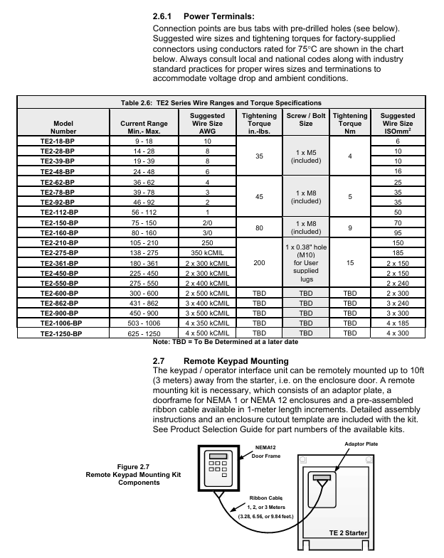
L1/L2/L3 (R/S/T) main power input three-phase 208-600VAC, requires circuit breaker/isolation switch TE2-18-BP: 10AWG, torque 35in lbs (M5 bolt)
T1/T2/T3 (U/V/W) motor output is connected to a three-phase motor, and reverse input/output TE2-1250-BP: 4 × 500kCMIL, torque TBD is strictly prohibited
The grounding terminal equipment shall be grounded according to NEC specifications, with a wire diameter not less than 1/2 of the phase wire. For example, a 10AWG phase wire shall be paired with an 8AWG grounding wire
(2) Control wiring (TB1 DC 24V, TB2 AC 120/240V)
TB1 (DC 24V) 1-3 3-wire control (Start/Stop) 1 connected to Start (NO), 2 connected to the common terminal, 3 connected to Stop (NC)
External interlock (NC) 4-5 connected to low oil level/high temperature switch, factory jumper needs to be removed
6-7 dual slope switch to external contacts, close and activate slope 2
7-8 Jog: Connect to external contacts, close to activate Jog (requires Start command)
9-10 analog output (4-20mA) connected to PLC/instrument, monitoring current/voltage/thermal capacity (F108 setting)
11-12 fault output (optocoupler Triac) connected to PLC, conducting in case of fault (240VAC/50mA max)
TB2 (AC control power supply) 21-22 (A1-A2) control power supply input 120VAC (standard), requires 1A fuse connection
13-20 auxiliary relay outputs 3 relays: 2 SPDT (13-18), 1 SPST (19-20), 240VAC/5A
Parameter programming
1. Core mandatory parameters
The rated current (FLA) of F001 motor must be set to the FLA on the motor nameplate, otherwise the soft starter will not operate. Range: 50-100%. The maximum current of the soft starter is 9-18A, such as TE2-18-BP
The service factor (SF) of F002 motor is set according to the motor nameplate, affecting the FLA upper limit 1.0 range of 1.00-1.30. If SF ↑, F001 can be set within the range ↓
F003/F004 Start/Run Overload Level NEMA Class 5-30, Match Motor Overload Capacity 10 (Class 10) Set High Level (e.g. Class 20) during Start to Avoid False Alarm
F010 Slope Type Selection: Choose Voltage/Current Slope and Double Slope Combination 1 (VR1+VR2). For heavy loads, choose CR, and for light loads, choose VR
F014/F018 maximum current limit limits the starting current and protects the power grid and motor by 350%. When the FLA power grid capacity is small, set it low (such as 250%), and when overloaded, set it high (such as 500%)
2. Programming operation process
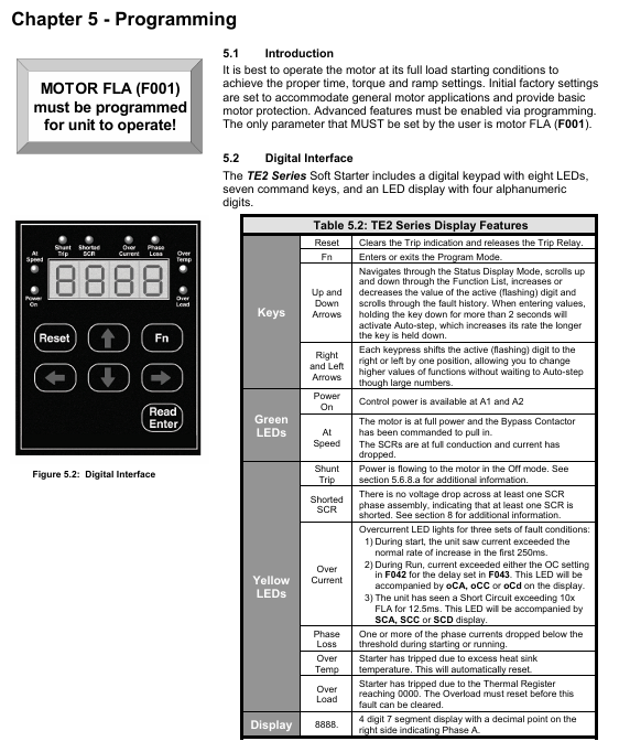
Enter programming mode: In the status display mode (default display of A-phase current), press the 【 Fn 】 key to enter the F001 parameter interface.
Adjust parameters:
Press the ←/→ key to select the digit to be modified (flashing);
Press the 【 ↑/↓ 】 keys to adjust the value (long press for 2 seconds to start automatic stepping);
Press the 【 ENT 】 key to save and display 'End' for confirmation.
Password protection:
Set F070 to a non-zero value (1-999) to enable the password, and enter the password for the next modification;
If you forget your password, please contact Toshiba customer service to restore the factory settings (F071=2) without clearing the password.
Communication programming: Connect PLC/upper computer through RS485 Modbus and modify parameter registers (such as register address 0x0001 corresponding to F001).
Startup and troubleshooting
1. Initiation process and inspection
Step operation content Key checkpoints
1. Confirm that the wiring of the main power supply, motor, and control power supply is correct, the grounding is reliable, and there is no looseness
The required parameters F001 (FLA), F002 (SF), and F010 (slope type) for parameter settings have been correctly configured
3. Power on test: Connect the control power supply, the "Power On" LED lights up and displays 【 0000. 】 (phase A has no current)
Press the Start button to start the test, the motor accelerates according to the set slope, the "At Speed" LED lights up (the motor reaches full speed), and the bypass contactor is closed
5. If the machine stops during startup, check the fault code (such as "oLA"=overload, increase F003)
2. Common faults and troubleshooting
Troubleshooting steps for fault codes and causes
NFLA motor FLA not set (F001=0) 1. Enter programming mode; 2. Let F001 be the motor nameplate FLA; 3. Restart after saving
1. Check if the main power supply L1/L2/L3 is out of phase during PLc operation; 2. Check if the motor wiring T1/T2/T3 is loose; 3. Confirm that the phase loss protection (F101) has not been mistakenly enabled
Overload during oLA startup: 1. Check if F003 (startup overload level) is too small (if set to Class 5), it can be increased to Class 15; 2. Check if the load is too heavy, reduce the starting load or increase the current limit (F014)
SSd SCR short circuit or no load 1. Disconnect the power supply and measure whether the SCR (L1-T1, L2-T2, L3-T3) is short circuited; 2. Confirm that the motor is connected (no load will report this fault)
Ground fault during GFc operation: 1. Check if the motor winding is grounded; 2. Check if the cable insulation is damaged; 3. Adjust the grounding fault threshold (F046) or delay (F047)
3. Fault recording and reset
Fault record: F085-F093 stores the last 3 faults, including fault codes (F085/F088/F091), timestamps (F086/F089/F092), and date stamps (F087/F090/F093).
Reset method:
Manual reset: After troubleshooting, press the [Reset] button. If there is an overload fault, wait for the motor to cool down (heat capacity H ≥ F059);
Automatic reset: F052 selects the fault type (such as 4=phase loss), F053 sets the reset frequency (1-10 times), 1 minute/time;
Remote reset: Disconnect the control power and reconnect it (applicable to scenarios without Reset button).
Maintenance and Appendix
1. Regular maintenance
Maintenance project cycle operation requirements
Clean the heat sink every 3 months (in dusty environments) and blow it with 80-100psi dry compressed air. Do not use chemicals/metal brushes
Check the power/control terminals for looseness every 6 months and tighten them again (according to torque requirements)
Fan inspection: Every year, listen to the running noise of the fan. If there is any abnormality, replace it (with a lifespan of 3 years/30000 hours)
Capacitor inspection: The main circuit capacitor has a lifespan of 10 years/73000h every 5 years. If it exceeds the lifespan, it is recommended to replace it
Backup parameters every year through BSD Configurator to avoid loss
2. Important Appendix Content
Appendix 1 (Slope Details): Detailed explanation of the differences in VR/CR slope curves. It is recommended to use VR for centrifugal pumps and CR for long conveyor belts.
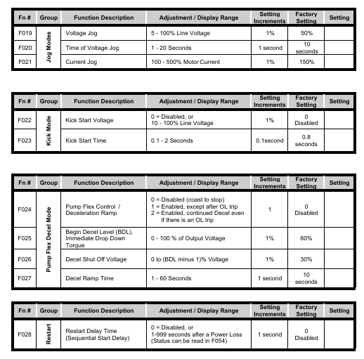
Appendix 2 (Pump Flex Deceleration): Used for soft stop of pumps to avoid water hammer effect, it is necessary to set the starting deceleration voltage (F025), stopping voltage (F026), and deceleration time (F027).
Appendix 3 (Password Protection): The process for handling lost passwords requires contacting Toshiba customer service for unlocking methods.
Appendix 4 (External Overload): When multiple motors are controlled or started by bypass, an external overload relay (OLR) is required. The wiring example is shown in document APP4.2.
Appendix 5 (Parameter Record): A blank table is used to record the parameters modified by the user for easy maintenance and traceability.
- YOKOGAWA
- Reliance
- ADVANCED
- SEW
- ProSoft
- WATLOW
- Kongsberg
- FANUC
- VSD
- DCS
- PLC
- man-machine
- Covid-19
- Energy and Gender
- Energy Access
- Renewable Integration
- Energy Subsidies
- Energy and Water
- Net zero emission
- Energy Security
- Critical Minerals
- A-B
- petroleum
- Mine scale
- Sewage treatment
- cement
- architecture
- Industrial information
- New energy
- Automobile market
- electricity
- Construction site
- HIMA
- ABB
- Rockwell
- Schneider Modicon
- Siemens
- xYCOM
- Yaskawa
- Woodward
- BOSCH Rexroth
- MOOG
- General Electric
- American NI
- Rolls-Royce
- CTI
- Honeywell
- EMERSON
- MAN
- GE
- TRICONEX
- Control Wave
- ALSTOM
- AMAT
- STUDER
- KONGSBERG
- MOTOROLA
- DANAHER MOTION
- Bentley
- Galil
- EATON
- MOLEX
- Triconex
- DEIF
- B&W
- ZYGO
- Aerotech
- DANFOSS
- KOLLMORGEN
- Beijer
- Endress+Hauser
- schneider
- Foxboro
- KB
- REXROTH
- YAMAHA
- Johnson
- Westinghouse
- WAGO
- TOSHIBA
- TEKTRONIX
- BENDER
- BMCM
- SMC
- HITACHI
- HIRSCHMANN
- XP POWER
- Baldor
- Meggitt
- SHINKAWA
- Other Brands
- UniOP
- KUKA
- IBA
- Beckhoff
-
ADLINK CPCI-6860A - 51-31310-OB10 industrial motherboard CompactPCI SBC
-
ADLINK AmITX-SL-G-H110 - 51-7A104-0A30 Mini-ITX Industrial Motherboard
-
ADLINK PXI-2005-003 - CPCI Industrial PC Data Acquisition Card Multi-Function DAQ
-
ADLINK DININ-814M - 51-14032-0A3D SCSI-100P cable connection Interface Terminal Board
-
ADLINK CPCI-3920NA/C2D15/M1G - 3U CompactPCI Intel Core 2 Duo Single Board Computer
-
ADLINK PCIE-8560 - 51-18014-0A20 Communication Card High Speed DAQ
-
ADLINK PCI-C154+ - Motion Control Card 4-axis Motion Controller Board
-
ADLINK PCI-RTV24 - image capture card Analog Video Frame Grabber
-
ADLINK NuPRO-842LV/P - 51-41360-0B30 Industrial Motherboard CPU Board
-
ADLINK cBP-3208/3208R - CPCI Board 3U 8-Slot CompactPCI Backplane
-
ADLINK PCI-8164 - 4-Axis Motion Controller PCI Card 51-12406-0A40
-
ADLINK PCIe-GIE64+ - 4-CH GigE Vision PoE+ Frame Grabber Video Capture Card
-
ADLINK CPCI-6860 / 6860A - CompactPCI Dual Xeon Single Board Computer
-
ADLINK IEC-915GV - REV 1.1 Industrial motherboard CPU Board
-
ADLINK ND-6520 - Technology RS-232 to RS-422RS-485 Converter NuDAM Module
-
ADLINK RTV-24 / PCI-MP4S - 51-12519-1C30 4-Channel Real Time Video Capture Board
-
ADLINK cPCI-6910 / cPCI-6910AM/M1G - cPCI-6910AM/DXL16/M1G/S80G(G)-3120 BOARD CompactPCI SBC
-
ADLINK NUPRO-A40H - Linghua 51-41807-1A30 Industrial Control Computer Motherboard
-
ADLINK USB-3488A - USB to GPIB INTERFACE USB-3488A(G) Controller Module
-
ADLINK PCI-8134A - motion control card 4-Axis Controller Card
-
ADLINK PCI-7432 - Board 32-Channel input / 32-output Isolated Digital I/O PCI Card
-
ADLINK PCI-8134A - 51-12421-0A10 motion controller card tested
-
ADLINK LPCIe-7230 - 32 CH Isolated Input/output Card 2 Interrupts Low Profile PCIe
-
ADLINK NuPRO-E340 - industrial computer motherboard 51-47807-0A30 PICMG 1.3 SHB
-
ADLINK PCI-7434 - High-speed Digital Acquisition Card 64-CH Isolated DO Card
-
ADLINK NuPRO-E330 - 51-41805-0A20 Indsutrial Board SHB Single Board Computer
-
ADLINK PCI-7248 - OPTO-22 48 CHANNEL DIO DIGITAL TTL/DTL I/O 51-12006-0A40 GP
-
ADLINK PCI-8134 - Motion control card 4-Axis Controller Card
-
ADLINK AMP-208C - Movimiento Control Tarjeta 51-12420-1A20 W/Expansión & Breakout
-
ADLINK PCI-8164 - 51-12406-0A40 PCB Board 4-Axis Motion Controller Card
-
ADLINK DIN-68Y-SGII / DIN-68M-J3A - Terminal Board Connector Interface Block
-
ADLINK PCIe-7432 - Technology 51-18402-0A10 PCIe Card With High Input Range
-
ADLINK PCI-8144 / PCI-8144N - Motion control card 4-Axis Stepper Controller Card
-
ADLINK HSL-HUB3/REPEATER - HIGH SPEED LINK EXTENSION MODULES Distributed Hub Module
-
ADLINK ND-6017 - Data Logging + Acquisition 8CH A/D input Mod NuDAM Module
-
ADLINK LPCIe-7250 - data acquisition card Low Profile 8-CH Relay Output Card
-
ADLINK PCI-7432 - I/O card 64-CH Isolated Digital Input Output PCI Card
-
ADLINK IMB-M43H - industrial control computer motherboard Q87 Chip Micro-ATX
-
ADLINK MP-C154 - Motion control Card 4-Axis Motion Controller Board
-
ADLINK PCI-RTV24 - image capture card Video Frame Grabber Card
-
ADLINK PCI-7250 - 8-CH Relay Output & 8-CH Isolated DI Card
-
ADLINK PCI-6308V - 8-CH 12-Bit Isolated Analog Output PCI Card PCB-I-E-1148=6EX2
-
ADLINK PCI-7248 - capture card 48-CH Opto-22 Compatible DIO Card
-
ADLINK HSL-AI16A02-M-VV - Analog Input Output Distributed Module
-
ADLINK NuPRO-A301 - Rev:1.4 NUPRO-A301 PICMG Full-Size Single Board Computer
-
ADLINK PCI-6208V-GL - 8-CH Voltage Analog Output PCI Card
-
ADLINK PCI-8134A - 51-12421-0A10 4-Axis Motion Controller Card
-
ADLINK MNET-S23 - TECHNOLOGY MNET S23 - SERVO DRIVER CONTROL MODULE
-
ADLINK M-342 - ATX I3 I5 I7 Q67 Industrial Motherboard
-
ADLINK NUPRO-780 - Industrial Motherboard CPU Board PICMG SBC
-
ADLINK MP-C154 / MP-C152 - 4-Axis Motion Control Card Pulse-Train Controller
-
ADLINK NuPRO-935A/LV10B0 - Motherboard 51-41802-0A10 GP w/RAM Industrial Control Board
-
ADLINK MP-C154 - Motion control card 4-Axis Motion Controller Mainboard
-
ADLINK PCI-7250 - PCI Acquisition Card 8-CH Relay Output Isolated DI Card
-
ADLINK ACL-7124 - Technology Inc.24 DIO Card Digital Input Output Card
-
ADLINK PCI-8554 A2 - Timer/Counter Data Acquisition Card
-
ADLINK DIN-825-GP4 - Terminal Block Interface Board Breakout Module
-
ADLINK NuPR0-761 - REV:1.1 Industrial motherboard Full-Size PICMG SBC
-
ADLINK MXE-1401/M8G (G) - Matrix Fanless Embedded Computer Industrial PC
-
ADLINK HSL-DI16DO16-UD-NN - Digital 16 Channel I/O Mod Distributed I/O Module
-
ADLINK ND6520 - NUDAM INTELLIGENT DA&C MODULE RS232-RS-422/RS485 CONVERTOR
-
ADLINK NUPRO-761 - REV:1.1 Industrial Motherboard CPU Board
-
ADLINK AMP-208C - Motion Control Card 51-12420-1A20 DSP-based 8-axis
-
ADLINK NuPRO-A301REV 1.4 - with packaging industrial computer motherboard PICMG SBC
-
ADLINK PCM-9112+ - 51-12300-0A2 industrial motherboard Multi-Function DAQ PC/104 Module
-
ADLINK PCM-7250+ - 8-CH Relay Outputs & 8-CH Isolated DI Module PC/104
-
ADLINK PCI-RTV24 - Image capture card Analog Video Frame Grabber
-
ADLINK PCI-8134 - Motion Controller PCI Card 4-Axis Controller Board
-
ADLINK PCI-7432 - Isolated Digital I/O PCI Card
-
ADLINK PCI-8554 A2 - acquisition card Timer/Counter Card
-
ADLINK PCI-8132 - Rev.A2 2-Axis Servo & Stepper Motion Controller Card
-
ADLINK PCI-8132 - Data Acquisition card 2-Axis Motion Controller Card
-
ADLINK EBP-13E4 - 51-46703-0A30 Industrial Backplane Board Passive Backplane
-
ADLINK PCI-800L - Electronic Card Interface Controller Card
-
ADLINK PCIe-GIE72 - 51-18531-0A10 PCB Board GigE Vision Frame Grabber
-
ADLINK DAQ-2010(G)-OOBO - Simultaneous-Sampling Multi-Function DAQ Card
-
ADLINK PCI-9112 - REV.B1 Multifunction DAQ Card Data Acquisition Card
-
ADLINK PCI-7230 - 51-12003-DA60 32-CH Isolated Digital I/O Card
-
ADLINK PCI-7432 - Data Acquisition Card Isolated Digital I/O PCI Card
-
ADLINK ETX-AT-N270-18/LXE - 51-71111-0A20 ETX CPU Module Motherboard
-
ADLINK HSL-DI32-UD-N - DIGITAL INPUT 32 POINTS MODULE Distributed I/O
-
ADLINK AMP-204C - Motion Control card DSP-Based 4-Axis Advanced Controller
-
ADLINK MNET-4XMOG-0050 - Four-axis Motion Controller Distributed Motion Module
-
ADLINK AMP-204C - Motion control card DSP-Based 4-Axis Pulse-Train Controller
-
ADLINK PCI-7442 - Switch card 64-Channel Datalogging & Acquisition Card
-
ADLINK M-302 - Industrial control motherboard ATX PC Board
-
ADLINK NUPRO-852 / NUPRO-852LV - Industrial motherboard Single Board Computer
-
ADLINK PCI-8134 - REV.B1. 4-Axis Motion Controller Card
-
ADLINK PCI-GIE62 + - 51-18502-0A20 2-CH GigE Vision Frame Grabber PoE Card
-
ADLINK PCI-MPG24 - 51-12523-0B20 MPEG4 Card Video Compression Hardware
-
ADLINK HSL-TB32-M-DIN - 32-CH I/O TERMINAL W/ HSL-AI16AO2-M-VV MODULE
-
ADLINK PCI-M114-GL - PCB Ver 2.1 Motion Controller Axis Card
-
ADLINK IMB-M40H - SYM76996H61 motherboard Industrial Computer Mainboard
-
ADLINK NUPRO-A40H - 51-41807-1A20 industrial control motherboard H61 Chip
-
ADLINK PCI-M114-GL - Axis Card Data Acquisition Card PCB VER2.2 Motion Controller
-
ADLINK PCI-8134 - Motion Controller PCI Card 4-Axis Controller Board
-
ADLINK PCI-8102 - Motion control card 2-Axis Servo & Stepper Controller
-
ADLINK NuPRO-841REV:3.0 - motherboard Industrial Control PC Board
-
ADLINK HSL-TB32-U-DIN REV A1 - Breakout Terminal Board Field I/O Module
-
ADLINK AMP-204C - Motion Control card DSP-Based 4-Axis Pulse-Train Controller
-
ADLINK NUPRO-A40H - 51-41807-1A20 industrial control motherboard H61 PC Board
-
ADLINK PCI-6308A / PCI-6308V - 51-12202-0A50 Isolated Analog Output Card
-
ADLINK AMP-204C - DSP-Based 4-Axis Advanced Pulse-Train Motion Controller
-
ADLINK PCI-7434 - Technology 64-Channel Isolated Digital I/O PCI Cards
-
ADLINK CPCI-6840 / CPCI-6840V / PM16/M1G-12G0 - CompactPCI Single Board Computer CPU Module
-
ADLINK PCIE-GIE74 - Motherboard Video Capture Card 51-18531-0A10 Frame Grabber
-
ADLINK NuPRO-E330 - industrial computer equipment motherboard Control Mainboard
-
ADLINK AMP-208C / 51-12420-1A20 - Motion Control Card W/ Expansion & Breakout Board
-
ADLINK HPCI-14S12U - industrial computer baseboard Passive Backplane 14 Slots
-
ADLINK PCI-8164 - 4-Axis Motion Controller PCI Card W/ 1x Cable, 1x Breakout Box
-
ADLINK PCIe-RTV24 - 51-18016-0A20 Image Acquisition Video Capture Card
-
ADLINK M-342 - 5 PCI ATX Motherboard Industrial PC Mainboard
-
ADLINK PCI-FIW64 - 4/2 Channel IEEE1394B Image Capture Card FireWire Frame Grabber
-
ADLINK PCI-7432 - digital IO card 64-CH Isolated Digital Input Output Card
-
ADLINK 51-12001-0C20 - Circuit Board PCI-7200 Data Acquisition Controller Card
-
ADLINK PXI-3920 - PXI 3U cPCI Industrial Controller Embedded System CPU Board
-
ADLINK NuPRO-841REV:2.0 - motherboard Industrial Control PC Board
-
ADLINK NuPro-E330 - 51-41805-0A20 PCB Industrial Control Computer Motherboard
-
ADLINK PCI-RTV24 - Image capture card Analog Video Frame Grabber
-
ADLINK PCI-7442 - Switch card 64-Channel Datalogging & Acquisition Card
-
ADLINK HPX-13S4 - device baseboard Passive Backplane Riser Card
-
ADLINK PCI-9112 REV A.1 - Multi Function DA&C Board Data Acquisition Card
-
ADLINK PCI-7248 - 51-12006-0A40 Card Control 48-CH Digital I/O Module
-
ADLINK CPCI-6860 / 6860A - motherboard CompactPCI Dual Xeon Single Board Computer
-
ADLINK DPAC-3020-11(G) - Embedded PC Automation Controller Machine Control Board
-
ADLINK NuPRO-841 REV:1.0 - industrial control motherboard CPU Board
-
ADLINK MNET-4XMOG-0050 - Four-axis Motion Controller MNET Motion Control Card
-
ADLINK ETX-AT-N270-18/LXE - 51-71111-0A20 ETX CPU Module Motherboard

K-JIANG

Add: Jimei North Road, Jimei District, Xiamen, Fujian, China
Tell:+86-15305925923