
K-WANG


Watlow Series 93 Controller
Watlow Series 93 Controller
Product Core Information
The Watlow Series 93 is a 1/16 DIN microprocessor based temperature controller with a single input dual output design. It supports J, K, T, N, S-type thermocouples, RTDs, or process signal (0-5V DC, 4-20mA) inputs, and outputs can be configured for heating, cooling, alarm, or shutdown functions. It has both PID and switch control modes and is suitable for industrial temperature control scenarios. The product complies with ISO 9001 standards, has an IP65 (NEMA 4X) protection level (optional), supports CE certification, provides a 3-year warranty, and is equipped with dual four digit red or green display screens by default, making it easy to operate.
Core functions and technical details
(1) Control mode and algorithm
PID control
Proportional band (Pb): The range can be set to 0-555 ° C (or ° F/unit), and it automatically switches to switch control when Pb=0; Under the SI unit, it is displayed in "% range" (0.0-999.9%), with a default value of 3%. The smaller the value, the higher the control sensitivity.
Integral/Reset (It/rE): Integral time 0.1-99.9 minutes/time (SI), reset frequency 0.01-99.9 times/minute (US), default 0, used to eliminate static deviation (droop) and avoid deviation from the set value after temperature stabilization.
Differential/Rate (dE/rA): 0.01-99.9 minutes, default 0, suppresses overshoot by predicting temperature trends, suitable for thermal systems with fast heating rates and high inertia.
Cycle time (Ct): 0.1-999.9 seconds, default 5 seconds. It is recommended to extend the cycle for mechanical relays to reduce contact wear, while solid-state relays can shorten the cycle to improve control accuracy.
Self tuning function
Trigger method: Set the [AUt] parameter in the operation menu (0=off, 1=slow, 2=medium, 3=fast), press the forward button to start, and after starting, the lower display screen will alternate between "[AUt]" and the current parameter.
Working principle: Based on 90% of the set value, the system's thermal characteristics are "learned" through 4 cross temperature points, and the optimal PID parameters are automatically calculated; If 4 crosses are not completed within 80 minutes, automatically exit and maintain the original parameters.
Applicable scenarios: Slow mode is suitable for scenarios where heating is slow and overshoot is not allowed (such as laboratory reactors), while fast mode is suitable for industrial heating furnaces and other scenarios where the set value needs to be quickly reached.
switch control
When the PID proportional band is set to 0, it is enabled, and the switching difference is defined by the [` HSC] parameter (1-55 ° C/1-99 ° F, default 2 ° C/3 ° F). When the temperature is below the set value - difference, the output is turned on, and when it is above the set value+difference, the output is turned off. It is suitable for scenarios with low control accuracy requirements (such as warehouse insulation).
(2) Alarm and safety functions
Alarm type configuration
**Process alarm ([PrA]/[Pr]) * *: Based on absolute temperature triggering, [ALO] (low alarm threshold, default range low limit) and [AHI] (high alarm threshold, default range high limit) need to be set in the operation menu. [PrA] will flash the alarm information, and [Pr] will only trigger the output without display.
**Deviation alarm (dEA/dE) * *: triggered based on the deviation of the set value, [ALO] range -999-0 (deviation below the set value), [AHI] range 0-999 (deviation above the set value), the alarm threshold automatically follows when the set value changes (e.g. set value of 100 ° F, deviation+7 ° F, alarm trigger point is 107 ° F).
Alarm auxiliary function
**Locked ([LAt]) * *: [LAt] (locked) needs to be manually cleared by pressing the infinite key, [` nLA] (non locked) will automatically clear when the temperature returns to the safe range, default is non locked.
**Silent (SIL) * *: Only deviation alarm is supported. When set to "On", press the infinite key to activate the alarm output when powered on. Even if the temperature exceeds the difference after activation, the alarm output will remain closed until the temperature returns to the safe range and the triggering ability is restored.
Hysteresis (HSA): 1-5555 ° C (or ° F/unit), default 2 ° C/3 ° F, to avoid frequent alarms caused by temperature fluctuations near the alarm threshold (e.g. alarm threshold of 100 ° C, hysteresis of 2 ° C, temperature drops below 98 ° C before the alarm is released).
(3) Auxiliary control function
Slope heating (rP)
Supports two modes: [Str] (only slopes from the current temperature to the set value when powered on), [On] (also slopes when the set value changes), with a ramp rate range of 0-9999 °/hour (default 100 °/hour), and the lower display screen alternately flashes "rP" and the target set value during the ramp process.
Applicable scenarios: To avoid damage to heating elements due to instantaneous high temperatures (such as glass melting furnaces), and to prevent deformation of workpieces due to excessive temperature differences (such as metal heat treatment).
Power Limit ([PL])
Only heating output is available, with a range of 0-100% (default 100%), limiting the maximum power of heating output to avoid load overload (such as when a small heater is adapted to a high-power controller, power should be limited to prevent burnout).
Calibration offset (CAL)
Range ± 100 ° C/± 180 ° F (or ± 180 units), default 0, used to compensate for measurement deviations caused by sensor installation errors or environmental interference (if the sensor is installed in a heat dissipation area and the actual temperature is 5 ° C higher than the measured value, a+5 ° C offset can be set).
Automatic/manual undisturbed switching
Switching mode: Press the infinite key twice to enter manual mode, the percentage indicator light remains on, and the lower display screen shows the output power (-100% to 100%, negative sign represents cooling); Press the infinite key again to return to automatic mode.
Non disruptive logic: When switching from automatic to manual mode, the output power remains at the PID calculated value before switching; When manually switching to automatic mode, transition to PID control starting from the current manual power to avoid sudden temperature changes.
Sensor fault handling: When the lock level [LOC] is 0/1/2, the sensor will automatically switch to manual mode after an open circuit (maintain the power before the fault, set to 0% if the power is unstable); Directly turn off the output at level 3/4.
Installation and wiring specifications
(1) Installation process
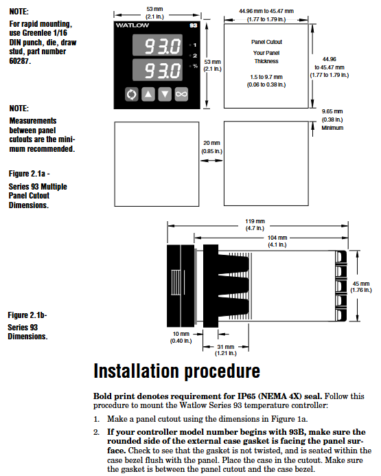
Panel preparation: Cut according to the size of 44.96-45.47mm (width x height). It is recommended to use Greenlee 60287 type 1/16 DIN punch, with a panel thickness of 1.5-9.7mm. When installing multiple units, the distance between adjacent cuts should be ≥ 20mm (to avoid heat dissipation interference).
Sealed installation (IP65 model):
Confirm that the housing gasket (circular with rounded corners) is facing the panel, without distortion or damage, and is embedded in the groove of the housing frame.
Insert the controller into the incision, press the panel side shell, insert the installation ring from the back, ensure that the installation ring buckle is aligned with the shell protrusion, press the buckle with your thumb until you hear a "click" sound, and check that the distance between the panel and the shell is ≤ 0.483mm (ensure sealing).
Dismantling method: Use a thin screwdriver or putty knife to gently pry open the 6 buckles of the installation ring, detach them one by one, and then shake the installation ring back and forth to remove it, avoiding pulling and damaging the shell with force.
(2) Wiring Details
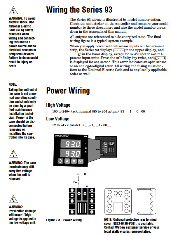
Power wiring
High voltage type (93_ -1 0-00): Terminal 11 is connected to L1 (100-240V AC, actually compatible with 85-264V), terminal 12 is connected to L2, built-in 1A slow melting fuse (250V), cannot be replaced with fast melting fuse.
Low voltage type (93_ -1 1-00 _): Terminal 11 is connected to positive (12-24V AC/DC, actually compatible with 10-26V), terminal 12 is connected to negative, with built-in 2A slow melting fuse. It is strictly prohibited to connect high voltage (which may cause irreversible damage).
Input wiring
Thermocouple: Terminal 3 is connected to the positive pole (if the red color of the J-type thermocouple is negative, pay attention to the polarity), terminal 5 is connected to the negative pole, and the extension wire should be made of the same material as the thermocouple (if the J-type thermocouple uses iron constantan material) to avoid errors; If the external device is not isolated, an isolated thermocouple should be used.
3-wire RTD: Terminal 2 is connected to S1, Terminal 3 is connected to S2, and Terminal 5 is connected to S3. The three leads must have the same specifications (same wire diameter and length), and the total lead resistance should be ≤ 20 Ω to avoid measurement errors caused by resistance differences; 2-wire RTD requires short circuiting terminals 3 and 5, resulting in low accuracy (+2 ° F error per 1 Ω lead resistance).
4-20mA signal: Terminal 2 is connected to the negative pole, terminal 5 is connected to the positive pole, and the input impedance is 5 Ω. It is necessary to ensure that the signal source and controller are grounded together to avoid grounding loops.
Output wiring
Mechanical relay (Output 1: Terminals 8/9/10): Terminal 8 is normally closed (NC), 9 is common terminal (COM), 10 is normally open (NO), maximum load 5A@240V Communication, inductive loads (such as relay coils) require parallel RC suppressors (Watlow 0804-0147-0000), minimum load 100mA@5V DC (to avoid contact oxidation).
4-20mA output (Output 1: Terminal 9/10): Terminal 9 is connected to the positive pole and 10 to the negative pole, with a maximum load impedance of 800 Ω. It is used to control actuators such as frequency converters and valves. Shielded wire is required for wiring, and the shielding layer is grounded at one end (controller end).
Safety Specifications
All wiring must comply with NEC and local electrical standards, with wire diameter of 20-14AWG and terminal torque of 1.4Nm (12in lb), to avoid poor contact caused by looseness and damage to terminals caused by tightness.
Disassembling the controller after power failure may result in residual voltage at the casing terminals, and insulated gloves should be worn during operation; When installing in high temperature environments, insulation pads should be added between the controller and the heat source to avoid ambient temperatures exceeding 65 ° C (rated operating limit).
Operation and Configuration
Buttons and Display: Equipped with forward key, infinite key, up and down arrow keys, the upper display screen displays process values, the lower display screen displays set values/parameters/alarm codes, and the percentage indicator light indicates manual mode (constantly on) or mode switching (flashing).
Menu navigation:
Settings menu (press and hold the up and down arrow keys for 3 seconds to enter): Configure input type, range, output mode, alarm parameters, lock level (0-4 levels, restrict parameter access permissions), etc.
Operation menu (press the forward button to enter): adjust PID parameters, alarm threshold, calibrate offset, start self-tuning, etc.
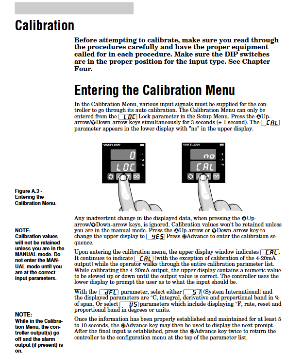
Calibration menu (enter by long pressing the up and down arrow keys from the settings menu): Supports thermocouples RTD、 The input/output calibration of process signals can restore the factory calibration values.
Core parameter configuration: The input type must be consistent with the internal DIP switch; The set value range is limited by [rL] (low range) and [rH] (high range); Output 1 defaults to heating, output 2 defaults to the opposite action of output 1, and can be changed to alarm function as needed.
Troubleshooting and Maintenance
Common error codes: [Er2] (RTD under range), [Er4] (configuration error), [Er5] (non-volatile memory verification error), [Er6]/[` Er7] (analog-to-digital conversion overflow/undercurrent, mostly due to sensor open circuit or polarity reversal). Error handling should be carried out according to the locking level, with manual mode switchable at lower levels and output directly turned off at higher levels.
Maintenance points: Regularly check the tightness of wiring and the status of sensors; The lifespan of mechanical relays is about 100000 cycles, and it is recommended to use solid-state relays for high-frequency switching; Non defective products must be returned in their original packaging within 120 days, with a 20% restocking fee. An RMA number must be obtained before repair.
- YOKOGAWA
- Reliance
- ADVANCED
- SEW
- ProSoft
- WATLOW
- Kongsberg
- FANUC
- VSD
- DCS
- PLC
- man-machine
- Covid-19
- Energy and Gender
- Energy Access
- Renewable Integration
- Energy Subsidies
- Energy and Water
- Net zero emission
- Energy Security
- Critical Minerals
- A-B
- petroleum
- Mine scale
- Sewage treatment
- cement
- architecture
- Industrial information
- New energy
- Automobile market
- electricity
- Construction site
- HIMA
- ABB
- Rockwell
- Schneider Modicon
- Siemens
- xYCOM
- Yaskawa
- Woodward
- BOSCH Rexroth
- MOOG
- General Electric
- American NI
- Rolls-Royce
- CTI
- Honeywell
- EMERSON
- MAN
- GE
- TRICONEX
- Control Wave
- ALSTOM
- AMAT
- STUDER
- KONGSBERG
- MOTOROLA
- DANAHER MOTION
- Bentley
- Galil
- EATON
- MOLEX
- Triconex
- DEIF
- B&W
- ZYGO
- Aerotech
- DANFOSS
- KOLLMORGEN
- Beijer
- Endress+Hauser
- schneider
- Foxboro
- KB
- REXROTH
- YAMAHA
- Johnson
- Westinghouse
- WAGO
- TOSHIBA
- TEKTRONIX
- BENDER
- BMCM
- SMC
- HITACHI
- HIRSCHMANN
- XP POWER
- Baldor
- Meggitt
- SHINKAWA
- Other Brands
- UniOP
- KUKA
- IBA
- Beckhoff
-
ADLINK CPCI-6860A - 51-31310-OB10 industrial motherboard CompactPCI SBC
-
ADLINK AmITX-SL-G-H110 - 51-7A104-0A30 Mini-ITX Industrial Motherboard
-
ADLINK PXI-2005-003 - CPCI Industrial PC Data Acquisition Card Multi-Function DAQ
-
ADLINK DININ-814M - 51-14032-0A3D SCSI-100P cable connection Interface Terminal Board
-
ADLINK CPCI-3920NA/C2D15/M1G - 3U CompactPCI Intel Core 2 Duo Single Board Computer
-
ADLINK PCIE-8560 - 51-18014-0A20 Communication Card High Speed DAQ
-
ADLINK PCI-C154+ - Motion Control Card 4-axis Motion Controller Board
-
ADLINK PCI-RTV24 - image capture card Analog Video Frame Grabber
-
ADLINK NuPRO-842LV/P - 51-41360-0B30 Industrial Motherboard CPU Board
-
ADLINK cBP-3208/3208R - CPCI Board 3U 8-Slot CompactPCI Backplane
-
ADLINK PCI-8164 - 4-Axis Motion Controller PCI Card 51-12406-0A40
-
ADLINK PCIe-GIE64+ - 4-CH GigE Vision PoE+ Frame Grabber Video Capture Card
-
ADLINK CPCI-6860 / 6860A - CompactPCI Dual Xeon Single Board Computer
-
ADLINK IEC-915GV - REV 1.1 Industrial motherboard CPU Board
-
ADLINK ND-6520 - Technology RS-232 to RS-422RS-485 Converter NuDAM Module
-
ADLINK RTV-24 / PCI-MP4S - 51-12519-1C30 4-Channel Real Time Video Capture Board
-
ADLINK cPCI-6910 / cPCI-6910AM/M1G - cPCI-6910AM/DXL16/M1G/S80G(G)-3120 BOARD CompactPCI SBC
-
ADLINK NUPRO-A40H - Linghua 51-41807-1A30 Industrial Control Computer Motherboard
-
ADLINK USB-3488A - USB to GPIB INTERFACE USB-3488A(G) Controller Module
-
ADLINK PCI-8134A - motion control card 4-Axis Controller Card
-
ADLINK PCI-7432 - Board 32-Channel input / 32-output Isolated Digital I/O PCI Card
-
ADLINK PCI-8134A - 51-12421-0A10 motion controller card tested
-
ADLINK LPCIe-7230 - 32 CH Isolated Input/output Card 2 Interrupts Low Profile PCIe
-
ADLINK NuPRO-E340 - industrial computer motherboard 51-47807-0A30 PICMG 1.3 SHB
-
ADLINK PCI-7434 - High-speed Digital Acquisition Card 64-CH Isolated DO Card
-
ADLINK NuPRO-E330 - 51-41805-0A20 Indsutrial Board SHB Single Board Computer
-
ADLINK PCI-7248 - OPTO-22 48 CHANNEL DIO DIGITAL TTL/DTL I/O 51-12006-0A40 GP
-
ADLINK PCI-8134 - Motion control card 4-Axis Controller Card
-
ADLINK AMP-208C - Movimiento Control Tarjeta 51-12420-1A20 W/Expansión & Breakout
-
ADLINK PCI-8164 - 51-12406-0A40 PCB Board 4-Axis Motion Controller Card
-
ADLINK DIN-68Y-SGII / DIN-68M-J3A - Terminal Board Connector Interface Block
-
ADLINK PCIe-7432 - Technology 51-18402-0A10 PCIe Card With High Input Range
-
ADLINK PCI-8144 / PCI-8144N - Motion control card 4-Axis Stepper Controller Card
-
ADLINK HSL-HUB3/REPEATER - HIGH SPEED LINK EXTENSION MODULES Distributed Hub Module
-
ADLINK ND-6017 - Data Logging + Acquisition 8CH A/D input Mod NuDAM Module
-
ADLINK LPCIe-7250 - data acquisition card Low Profile 8-CH Relay Output Card
-
ADLINK PCI-7432 - I/O card 64-CH Isolated Digital Input Output PCI Card
-
ADLINK IMB-M43H - industrial control computer motherboard Q87 Chip Micro-ATX
-
ADLINK MP-C154 - Motion control Card 4-Axis Motion Controller Board
-
ADLINK PCI-RTV24 - image capture card Video Frame Grabber Card
-
ADLINK PCI-7250 - 8-CH Relay Output & 8-CH Isolated DI Card
-
ADLINK PCI-6308V - 8-CH 12-Bit Isolated Analog Output PCI Card PCB-I-E-1148=6EX2
-
ADLINK PCI-7248 - capture card 48-CH Opto-22 Compatible DIO Card
-
ADLINK HSL-AI16A02-M-VV - Analog Input Output Distributed Module
-
ADLINK NuPRO-A301 - Rev:1.4 NUPRO-A301 PICMG Full-Size Single Board Computer
-
ADLINK PCI-6208V-GL - 8-CH Voltage Analog Output PCI Card
-
ADLINK PCI-8134A - 51-12421-0A10 4-Axis Motion Controller Card
-
ADLINK MNET-S23 - TECHNOLOGY MNET S23 - SERVO DRIVER CONTROL MODULE
-
ADLINK M-342 - ATX I3 I5 I7 Q67 Industrial Motherboard
-
ADLINK NUPRO-780 - Industrial Motherboard CPU Board PICMG SBC
-
ADLINK MP-C154 / MP-C152 - 4-Axis Motion Control Card Pulse-Train Controller
-
ADLINK NuPRO-935A/LV10B0 - Motherboard 51-41802-0A10 GP w/RAM Industrial Control Board
-
ADLINK MP-C154 - Motion control card 4-Axis Motion Controller Mainboard
-
ADLINK PCI-7250 - PCI Acquisition Card 8-CH Relay Output Isolated DI Card
-
ADLINK ACL-7124 - Technology Inc.24 DIO Card Digital Input Output Card
-
ADLINK PCI-8554 A2 - Timer/Counter Data Acquisition Card
-
ADLINK DIN-825-GP4 - Terminal Block Interface Board Breakout Module
-
ADLINK NuPR0-761 - REV:1.1 Industrial motherboard Full-Size PICMG SBC
-
ADLINK MXE-1401/M8G (G) - Matrix Fanless Embedded Computer Industrial PC
-
ADLINK HSL-DI16DO16-UD-NN - Digital 16 Channel I/O Mod Distributed I/O Module
-
ADLINK ND6520 - NUDAM INTELLIGENT DA&C MODULE RS232-RS-422/RS485 CONVERTOR
-
ADLINK NUPRO-761 - REV:1.1 Industrial Motherboard CPU Board
-
ADLINK AMP-208C - Motion Control Card 51-12420-1A20 DSP-based 8-axis
-
ADLINK NuPRO-A301REV 1.4 - with packaging industrial computer motherboard PICMG SBC
-
ADLINK PCM-9112+ - 51-12300-0A2 industrial motherboard Multi-Function DAQ PC/104 Module
-
ADLINK PCM-7250+ - 8-CH Relay Outputs & 8-CH Isolated DI Module PC/104
-
ADLINK PCI-RTV24 - Image capture card Analog Video Frame Grabber
-
ADLINK PCI-8134 - Motion Controller PCI Card 4-Axis Controller Board
-
ADLINK PCI-7432 - Isolated Digital I/O PCI Card
-
ADLINK PCI-8554 A2 - acquisition card Timer/Counter Card
-
ADLINK PCI-8132 - Rev.A2 2-Axis Servo & Stepper Motion Controller Card
-
ADLINK PCI-8132 - Data Acquisition card 2-Axis Motion Controller Card
-
ADLINK EBP-13E4 - 51-46703-0A30 Industrial Backplane Board Passive Backplane
-
ADLINK PCI-800L - Electronic Card Interface Controller Card
-
ADLINK PCIe-GIE72 - 51-18531-0A10 PCB Board GigE Vision Frame Grabber
-
ADLINK DAQ-2010(G)-OOBO - Simultaneous-Sampling Multi-Function DAQ Card
-
ADLINK PCI-9112 - REV.B1 Multifunction DAQ Card Data Acquisition Card
-
ADLINK PCI-7230 - 51-12003-DA60 32-CH Isolated Digital I/O Card
-
ADLINK PCI-7432 - Data Acquisition Card Isolated Digital I/O PCI Card
-
ADLINK ETX-AT-N270-18/LXE - 51-71111-0A20 ETX CPU Module Motherboard
-
ADLINK HSL-DI32-UD-N - DIGITAL INPUT 32 POINTS MODULE Distributed I/O
-
ADLINK AMP-204C - Motion Control card DSP-Based 4-Axis Advanced Controller
-
ADLINK MNET-4XMOG-0050 - Four-axis Motion Controller Distributed Motion Module
-
ADLINK AMP-204C - Motion control card DSP-Based 4-Axis Pulse-Train Controller
-
ADLINK PCI-7442 - Switch card 64-Channel Datalogging & Acquisition Card
-
ADLINK M-302 - Industrial control motherboard ATX PC Board
-
ADLINK NUPRO-852 / NUPRO-852LV - Industrial motherboard Single Board Computer
-
ADLINK PCI-8134 - REV.B1. 4-Axis Motion Controller Card
-
ADLINK PCI-GIE62 + - 51-18502-0A20 2-CH GigE Vision Frame Grabber PoE Card
-
ADLINK PCI-MPG24 - 51-12523-0B20 MPEG4 Card Video Compression Hardware
-
ADLINK HSL-TB32-M-DIN - 32-CH I/O TERMINAL W/ HSL-AI16AO2-M-VV MODULE
-
ADLINK PCI-M114-GL - PCB Ver 2.1 Motion Controller Axis Card
-
ADLINK IMB-M40H - SYM76996H61 motherboard Industrial Computer Mainboard
-
ADLINK NUPRO-A40H - 51-41807-1A20 industrial control motherboard H61 Chip
-
ADLINK PCI-M114-GL - Axis Card Data Acquisition Card PCB VER2.2 Motion Controller
-
ADLINK PCI-8134 - Motion Controller PCI Card 4-Axis Controller Board
-
ADLINK PCI-8102 - Motion control card 2-Axis Servo & Stepper Controller
-
ADLINK NuPRO-841REV:3.0 - motherboard Industrial Control PC Board
-
ADLINK HSL-TB32-U-DIN REV A1 - Breakout Terminal Board Field I/O Module
-
ADLINK AMP-204C - Motion Control card DSP-Based 4-Axis Pulse-Train Controller
-
ADLINK NUPRO-A40H - 51-41807-1A20 industrial control motherboard H61 PC Board
-
ADLINK PCI-6308A / PCI-6308V - 51-12202-0A50 Isolated Analog Output Card
-
ADLINK AMP-204C - DSP-Based 4-Axis Advanced Pulse-Train Motion Controller
-
ADLINK PCI-7434 - Technology 64-Channel Isolated Digital I/O PCI Cards
-
ADLINK CPCI-6840 / CPCI-6840V / PM16/M1G-12G0 - CompactPCI Single Board Computer CPU Module
-
ADLINK PCIE-GIE74 - Motherboard Video Capture Card 51-18531-0A10 Frame Grabber
-
ADLINK NuPRO-E330 - industrial computer equipment motherboard Control Mainboard
-
ADLINK AMP-208C / 51-12420-1A20 - Motion Control Card W/ Expansion & Breakout Board
-
ADLINK HPCI-14S12U - industrial computer baseboard Passive Backplane 14 Slots
-
ADLINK PCI-8164 - 4-Axis Motion Controller PCI Card W/ 1x Cable, 1x Breakout Box
-
ADLINK PCIe-RTV24 - 51-18016-0A20 Image Acquisition Video Capture Card
-
ADLINK M-342 - 5 PCI ATX Motherboard Industrial PC Mainboard
-
ADLINK PCI-FIW64 - 4/2 Channel IEEE1394B Image Capture Card FireWire Frame Grabber
-
ADLINK PCI-7432 - digital IO card 64-CH Isolated Digital Input Output Card
-
ADLINK 51-12001-0C20 - Circuit Board PCI-7200 Data Acquisition Controller Card
-
ADLINK PXI-3920 - PXI 3U cPCI Industrial Controller Embedded System CPU Board
-
ADLINK NuPRO-841REV:2.0 - motherboard Industrial Control PC Board
-
ADLINK NuPro-E330 - 51-41805-0A20 PCB Industrial Control Computer Motherboard
-
ADLINK PCI-RTV24 - Image capture card Analog Video Frame Grabber
-
ADLINK PCI-7442 - Switch card 64-Channel Datalogging & Acquisition Card
-
ADLINK HPX-13S4 - device baseboard Passive Backplane Riser Card
-
ADLINK PCI-9112 REV A.1 - Multi Function DA&C Board Data Acquisition Card
-
ADLINK PCI-7248 - 51-12006-0A40 Card Control 48-CH Digital I/O Module
-
ADLINK CPCI-6860 / 6860A - motherboard CompactPCI Dual Xeon Single Board Computer
-
ADLINK DPAC-3020-11(G) - Embedded PC Automation Controller Machine Control Board
-
ADLINK NuPRO-841 REV:1.0 - industrial control motherboard CPU Board
-
ADLINK MNET-4XMOG-0050 - Four-axis Motion Controller MNET Motion Control Card
-
ADLINK ETX-AT-N270-18/LXE - 51-71111-0A20 ETX CPU Module Motherboard

K-JIANG

Add: Jimei North Road, Jimei District, Xiamen, Fujian, China
Tell:+86-15305925923