
K-WANG


Watlow Series 942 Controller
Input type: compatible with J, K, T, N, R, S, B, C, Pt2 thermocouples, RTD (2-wire or 3-wire) and 0-5VDC, 4-20mA process inputs.
Programming ability: Supports 24 step program curves, including four step types: set point (StPt), constant temperature (SoAh), jump cycle (JL), and end, and can achieve multi-stage temperature control.
Auxiliary functions: optional dual auxiliary output (alarm or time triggered event), set point/process value retransmission output, supports RS-422A/RS-423A/EIA-485 communication interface.
Data storage: Non volatile memory automatically saves all parameters, and data is not lost after power failure; Lithium battery backup operation parameters, with a service life of about 10 years.
Watlow Series 942 Controller
Core features and specifications of the product
core functionality
Control mode: Supports PID or ON/OFF control, can be manually selected; Dual output design, output 1 can be set as heating or cooling, and output 2 can be set as heating, cooling, or off.
Input type: compatible with J, K, T, N, R, S, B, C, Pt2 thermocouples, RTD (2-wire or 3-wire) and 0-5VDC, 4-20mA process inputs.
Programming ability: Supports 24 step program curves, including four step types: set point (StPt), constant temperature (SoAh), jump cycle (JL), and end, and can achieve multi-stage temperature control.
Auxiliary functions: optional dual auxiliary output (alarm or time triggered event), set point/process value retransmission output, supports RS-422A/RS-423A/EIA-485 communication interface.
Data storage: Non volatile memory automatically saves all parameters, and data is not lost after power failure; Lithium battery backup operation parameters, with a service life of about 10 years.
Key specifications
Temperature range: thermocouple (-328 ° F~4200 ° F/-200 ° C~2315 ° C), RTD (-328 ° F~1112 ° F/-200 ° C~600 ° C), process input (-500~3500 units).
Accuracy: ± 0.1% ± 1 LSD of full scale (ambient temperature 77 ° F ± 5 ° F, rated voltage ± 10%).
Output specifications:
Solid state relay output: 0.5A@24-264VAC Optical isolation and zero crossing switching.
Mechanical relay output: 6A@120 /240VAC or 28VDC.
Process output: 0-5VDC/0-10VDC (minimum load 10K Ω), 4-20mA/0-20mA (maximum load 600 Ω).
Working environment: Temperature range of 32 ° F~149 ° F (0 ° C~65 ° C), humidity range of 0~90% (no condensation).
Installation and wiring process
Installation preparation
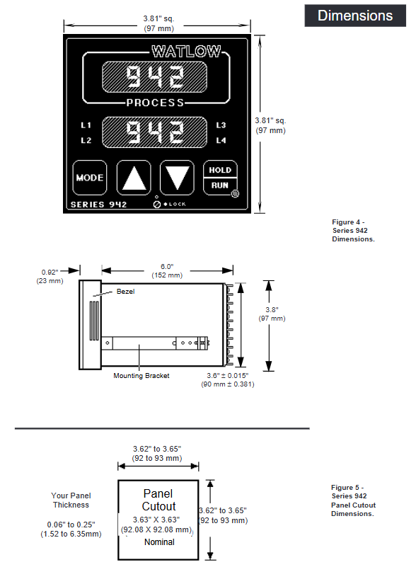
Panel Hole: Process panel holes according to size requirements (nominal 3.625 × 3.625 inches/92.08 × 92.08mm, thickness 0.06~0.25 inches/1.5~6.35mm).
Equipment fixation: Insert the controller housing into the opening, fix it from the back of the panel with the matching bracket, then insert the control chassis into the housing and lock it by rotating the front plate screw 90 ° clockwise (note that the screw should only be rotated 90 ° to avoid excessive force damage).
Wiring operation
Power wiring
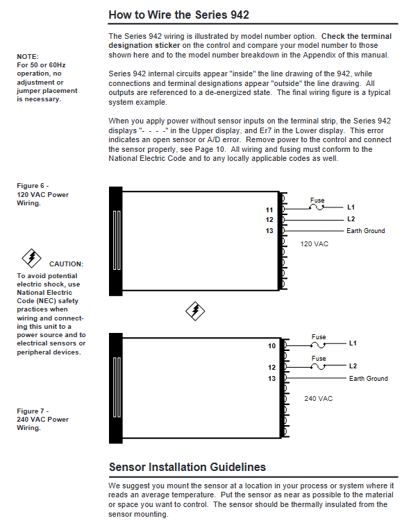
Supports 120VAC or 240VAC power supply (50/60Hz universal, no adjustment required), requires connection to L1 and L2 power terminals and grounding terminals, and wiring must comply with the National Electrical Code (NEC) to avoid the risk of electric shock.
The power supply end needs to be connected in series with a fuse. When powered by 120VAC, the L1 end needs to be connected in series with a fuse. When powered by 240VAC, both the L1 and L2 ends need to be connected in series with a fuse.
Sensor wiring
Thermocouple: Use extension cords made of the same material as the thermocouple to avoid errors; If connecting non isolated external devices, an isolated thermocouple should be selected, with positive and negative terminals corresponding to terminals 7 (+) and 9 (-).
RTD: 2-wire RTD needs to short-circuit terminals 5 and 6, and 3-wire RTD needs to ensure that the resistance of the three extension wires is consistent (with the same wire diameter and material) to compensate for lead resistance errors (every 1 Ω lead resistance of 2-wire RTD will cause an error of about+2 ° C).
Process input: 0-5VDC input is connected to terminals 1 (+) and 3 (-), with an input impedance of 100K Ω; 4-20mA input requires short circuiting terminals 2 and 3, followed by connecting the positive and negative poles of the signal, with an input impedance of 249 Ω.
Output wiring
Output 1/2: Select the wiring method according to the model (solid-state relay, mechanical relay, DC switch, process output, etc.), refer to the wiring diagram of the corresponding model in the manual for details, and ensure that the load impedance matches (such as process output 4-20mA maximum load 600 Ω).
Auxiliary output: 6 auxiliary options are available (single relay, dual relay, relay+retransmission, etc.), wired according to the corresponding terminals (24-27) of the model, and the alarm/event output is a mechanical relay( 6A@28VDC /120VAC)。
Wiring precautions
Separation of strong and weak electricity: The sensor signal line (low power) is wired separately from the power line and output line (high power), with a minimum spacing of 12 inches (305mm) to avoid cross interference; When crossing, use a 90 ° crossing.
Shielding and grounding: Shielded cables are used for low-level signal lines, and the shielding layer is only grounded at the controller end; The system is grounded at a single point to avoid grounding loops, and all grounding terminals are connected to a unified grounding body.
Parameter Configuration Guide
Enter the configuration menu
Press the UP and DOWN keys simultaneously for 3 seconds to enter the Setup menu (displaying LOC parameters); Continue holding down the UP and DOWN keys under the LOC parameter to enter the calibration menu.
During the configuration process, press the MODE key to switch parameters, use the UP/DOWN key to adjust values, and if there is no operation for 5 seconds, it will automatically save and return to the previous level, or press the MODE key to manually save and switch.
Key configuration parameters (Setup menu)
Parameter Category Core Parameter Function Description Default Values
Security and Permission LOC Operation Permission Lock (Level 0-3): Level 0 Full Permission, Level 3 Only View Setpoint/Process Values 0
Input configuration In Select input type (such as J, K, RTD, 4-20, etc.) J or r
Temperature unit (° F/° C), only displays F when input as thermocouple/RTD
The upper and lower limits of the range for the rL/rH set point/process input, as well as the default range for scaling and retransmitting the output range of the sensor
Output configuration Ot1/Ot2 output 1/2 action type (ht heating/CL cooling/no off) ht/CL
HYS1/HYS2 output 1/2 ON/OFF switching hysteresis (effective when Pb=0) 3 ° F
Alarm and event Ot3/Ot4 auxiliary output 3/4 function (AL alarm/Ent event/PrOC retransmission) AL/PrOC
AL1/AL2 alarm type (Pr process alarm/DE deviation alarm) Pr
Programming configuration PtYP program type (ti time basis/ratE ramp rate basis) ti
GSD constant temperature deviation window (program pauses when out of range) 0 (disabled)
Power outage recovery Pout program recovery method after power outage (Cont continue/HOLD hold/Abrt abort) Cont
Communication configuration: bAUD baud rate (300-9600), only models with communication function display 1200
Addr device address (0-31), only displaying 0 under FULL protocol
Operation menu parameters (Operation menu)
Setpoint (SP): Adjust the control target value within the range of rL~rH, and display OFF (disable all outputs) when it is lower than rL.
PID parameters (Pb1/Pr2, rE1/rE2, rA1/rA2): proportional band, reset/integral, rate/derivative, automatically generated after automatic tuning, or manually adjustable.
Automatic tuning (Aut): Only output 1 for heating display, select tuning rate (1 slow/2/3 fast), and the controller automatically optimizes PID parameters after startup.
Alarm setting (A1LO/A1HI, A2LO/A2HI): Process alarm setting upper and lower limits (Pr type) or deviation alarm offset (dE type).
Program Programming and Running
Fundamentals of Programming
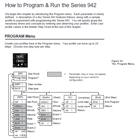
Program structure: Up to 24 steps, each step can be selected from four types: StPt (Setpoint Slope), SoAh (Constant Temperature Holding), JL (Jump Loop), and End (Program End), supporting multiple program concatenation (a new program can start after one End step).
Programming entrance: Select Prog=YES from the Operation menu to enter the Program menu. Press the StEP parameter to select steps (1-24), and press StYP to select the step type.
Detailed explanation of four step programming methods
1. Set point step (StPt)
Core parameters:
SP: Target Set Point (rL~rH).
Time basis (PtYP=ti): HOUr/Min/SEC, total time is the sum of the three (0-23h59m59s).
Rate basis (PtYP=rAtE): rAtE, temperature change rate (0-360 ° F/min or 0-200 ° C/min).
Ent1/Ent2: On/Off status of event 1/2, displayed only when Ot3/Ot4 is set to Ent.
Example: Step 1 is set to StPt, SP=75 ° F, Min=0, SEC=1, Ent1=OFF, achieving the initial setting of reaching 75 ° F within 1 second.
2. Constant temperature step (SoAh)
Core parameters: HOUr/Min/SEC (constant temperature duration), Ent1/Ent2 (event switch), no SP parameter (inherited from the previous set point).
Example: Set Step 3 to SoAh, Min=0, SEC=25, Ent1=On, achieve 25 seconds of constant temperature and trigger Event 1.
3. Jump loop step (JL)
Core parameters:
JS: Jump to the target step (must be smaller than the current step, cannot jump to itself).
JC: Jump count (0=infinite loop, 1-100=finite loop).
Example: Set Step 6 to JL, JS=2, JC=1, implement a jump to Step 2 and repeat once (execute Steps 2-5 twice in total).
4. End step
Core parameters: End (HOLD remains in the last state/OFF closes all outputs/OFFA closes control outputs, retains alarms).
Example: Step 4 is set to End, End=OFF. After the program ends, all outputs are turned off, and 'lower' displays' OFF '.
Program Execution and Control
Start program: In the non Setup menu interface, press the HOLD/RUN button, the RUN LED flashes, select the Start Step (StP), then press the HOLD/RUN button to confirm, the RUN LED stays on, and the program starts.
Pause and Resume: Press the HOLD/RUN button once to pause (RUN LED flashes); Press the HOLD/RUN key again to switch to the rESU parameter, and press the HOLD/RUN key to resume operation (only when the program has not been modified).
View operating status: Press the MODE key to switch parameters in the RUN menu, where you can view remaining time (HOUr/Min/SEC), current rate (rAtE), event status (Ent1/Ent2), etc.
Programming Example (Slope Constant Temperature Cycle)
Requirement: Initial temperature of 75 ° F → 25 seconds to rise to 100 ° F (event 1 activated) → 25 seconds constant temperature → 25 seconds to rise to 125 ° F (event 2 activated) → 25 seconds constant temperature → jump to step 1 and repeat twice → maintain the final state.
Step by step SP (° F) Time (minutes: seconds) Ent1 Ent2 JS JC End
1 StPt 75 0:01 OFF OFF - - -
2 StPt 100 0:25 ON OFF - - -
3 SoAh - 0:25 ON OFF - - -
4 StPt 125 0:25 OFF ON - - -
5 SoAh - 0:25 ON OFF - - -
6 JL - - - - 1 2 -
7 End - - - - - - HOLd
Tuning operation (automatic and manual)
Automatic tuning (recommended)
Applicable scenario: Quickly obtain optimized PID parameters after first use and system load changes.
Operation steps:
Enter the Operation menu and find the Aut parameter (displayed only when Ot1=ht).
Press the UP/DOWN keys to select the tuning rate (1 slow/2/3 fast, mostly 2 in most scenarios).
Press the MODE key to start tuning, and the lower display alternately flashes Aut and the current parameter. During tuning, the cooling output is turned off, and the heating output runs at 90% set point ON/OFF.
Complete tuning within 80 minutes, automatically save PID parameters, restore Aut to 0, and return to normal control mode; Modifying the set point during tuning will restart tuning. Press the UP/DOWN key to set Aut=0 to abort (restore the original parameters).
Manual tuning (precise optimization)
Operation steps:
Initialization parameters: Pb1=1, Ct1=5, rE1=rA1=0, CAL=0, Aut=0, set target temperature.
Proportional band (Pb1) adjustment: gradually increase Pb1 until the process temperature stabilizes (initial reset to 0, temperature may deviate from the set point).
Reset/Integral (rE1) Adjustment: Gradually increase rE1 until the temperature begins to oscillate, then slowly decrease until the temperature stabilizes near the set point.
Rate/Differential (rA1) Adjustment: Assuming rA1=1.00 minutes, raise the set point by 20-30 ° F. If the temperature is overshoot, increase rA1 (maximum 9.99) to avoid overshoot and slow response.
Cycle time (Ct1) adjustment: Optimized within the range of 1-60 seconds. It is recommended to choose a longer cycle time for mechanical contactors (to reduce wear) and a shorter time for electronic loads (to improve control accuracy).
Alarm and fault handling
Alarm function operation
Alarm type:
Process alarm (Pr): Based on the absolute temperature threshold (A1LO/A1HI), an alarm is triggered when the temperature exceeds the range.
Deviation alarm (dE): Based on the set point offset (such as+7 ° F/-5 ° F), the alarm threshold synchronously shifts when the set point changes.
Alarm status:
Non Locked (nLA): Automatically resets after the alarm condition disappears.
Lock (LAt): Manual reset is required (first eliminate the alarm condition, then press the HOLD/RUN button).
Alarm indication: The lower display alternately flashes "LO"/"HI" and the current parameter, the L3/L4 LED lights up, and the auxiliary output triggers (N.O. closed/N.C. open).
Common faults and solutions
Fault symptoms, error codes, possible causes, and solutions
The upper display shows "----", the lower display shows Er7 Er7 A/D overflow, the sensor is open/polarity reversed, check the sensor wiring (positive and negative poles, terminal contact), confirm that the In parameter is consistent with the sensor type
The upper display shows "----", the lower display shows Er1/Er2 Er1/Er2 sensor over/under range, A/D fault confirms that the sensor range matches rL/rH, checks if the sensor is damaged, and recalibrates the A/D
Pause during program operation - gSD deviation window enabled, adjust gSD value if temperature exceeds ± gSD range (increase window), check if heating/cooling system is normal, eliminate load interference
Communication failure - baud rate/protocol/address mismatch, wiring error. Confirm that bAUd (baud rate), Prot (protocol), Addr (address) in the Setup menu are consistent with the host, and check the communication line wiring (RS-485 requires corresponding A/B lines)
Large temperature measurement error - sensor wiring error, calibration offset, environmental interference. Reconnect and confirm sensor type, enter Cal menu to adjust CAL offset, check signal line shielding and grounding
Output unresponsive - Set the set point to OFF, configure the output type incorrectly, adjust the SP to the rL~rH range for load faults, confirm the Ot1/Ot2 parameters (ht/CL), check if the load impedance matches the output type, and test if the load is normal
Calibration operation (accuracy calibration)
Calibration prerequisite
Only enter under LOC parameters and require precise equipment (such as precision millivolt source, resistance box, voltage/current source, 4.5-inch multimeter).
Backup all parameters (Setup/Operation/Program) before calibration, turn off all outputs during calibration (except for process outputs), and automatically save calibration values when the RUN LED lights up.
Core Calibration Process (Taking Thermocouples as an Example)
Wiring: Connect the precision millivolt source to terminals 7 (+) and 9 (-), connect to AC power and ground.
Preheating: Power on for 15 minutes, enter the Cal menu (hold down the UP/DOWN key under LOC parameters), press the MODE key to select the tCL parameter.
Low range calibration: The millivolt source outputs 0.00mV, and after stabilizing for 10 seconds, press the MODE button.
High range calibration: J-type thermocouple outputs 50.00mV, R/S/B type outputs 16.035mV. After stabilizing for 10 seconds, press the MODE button.
Compensation calibration: Disconnect the millivolt source and connect the J-type reference compensator (32 ° F/0 ° C). After stabilizing for 10 seconds, press the HOLD/RUN button to exit the RUN mode and complete the calibration.
Other calibrations (RTD/process input/output)
RTD calibration: Use a 1K Ω precision resistance box to connect terminals 4-6, and input low/high resistance values according to the rLO/rHI parameters (refer to Table 7 in the manual).
4-20mA input calibration: Short circuit terminals 2-3, output 4.00mA (4A parameter) and 20.00mA (20A parameter) from the current source, and calibrate sequentially.
Process output calibration: Connect a multimeter and a matching resistor (such as 4-20mA connected to a 470 Ω resistor), adjust the output to the target value (such as 4.00mA/20.00mA) according to the O1LO/O1HI parameters.
Maintenance and Precautions
routine maintenance
Regular inspection: Check whether the sensor wiring is loose or corroded, whether the panel screws are tightened, and whether the heat dissipation is good.
Battery replacement: Lithium batteries (with backup operating parameters) have a lifespan of about 10 years. In case of abnormal Pout or Run parameters, they need to be returned to the factory for replacement.
Cleaning and maintenance: Wipe the panel with a dry soft cloth to prevent liquid from seeping into the interior of the equipment; Avoid using in damp, dusty, and corrosive environments.
Safety precautions
Disconnect the power supply before wiring, strictly follow NEC and local electrical regulations, and ensure reliable grounding (to avoid electric shock and interference).
The front plate screws should only be rotated 90 °, and excessive force should be avoided to avoid damaging the chassis locking structure.
Mercury relays are only suitable for resistive loads and are prohibited from being used for inductive loads (such as motors without buffering).
Calibration and maintenance must be carried out by professional personnel, and unauthorized disassembly of the equipment casing is prohibited (which may affect warranty).
- YOKOGAWA
- Reliance
- ADVANCED
- SEW
- ProSoft
- WATLOW
- Kongsberg
- FANUC
- VSD
- DCS
- PLC
- man-machine
- Covid-19
- Energy and Gender
- Energy Access
- Renewable Integration
- Energy Subsidies
- Energy and Water
- Net zero emission
- Energy Security
- Critical Minerals
- A-B
- petroleum
- Mine scale
- Sewage treatment
- cement
- architecture
- Industrial information
- New energy
- Automobile market
- electricity
- Construction site
- HIMA
- ABB
- Rockwell
- Schneider Modicon
- Siemens
- xYCOM
- Yaskawa
- Woodward
- BOSCH Rexroth
- MOOG
- General Electric
- American NI
- Rolls-Royce
- CTI
- Honeywell
- EMERSON
- MAN
- GE
- TRICONEX
- Control Wave
- ALSTOM
- AMAT
- STUDER
- KONGSBERG
- MOTOROLA
- DANAHER MOTION
- Bentley
- Galil
- EATON
- MOLEX
- Triconex
- DEIF
- B&W
- ZYGO
- Aerotech
- DANFOSS
- KOLLMORGEN
- Beijer
- Endress+Hauser
- schneider
- Foxboro
- KB
- REXROTH
- YAMAHA
- Johnson
- Westinghouse
- WAGO
- TOSHIBA
- TEKTRONIX
- BENDER
- BMCM
- SMC
- HITACHI
- HIRSCHMANN
- XP POWER
- Baldor
- Meggitt
- SHINKAWA
- Other Brands
- UniOP
- KUKA
- IBA
- Beckhoff
-
ADLINK CPCI-6860A - 51-31310-OB10 industrial motherboard CompactPCI SBC
-
ADLINK AmITX-SL-G-H110 - 51-7A104-0A30 Mini-ITX Industrial Motherboard
-
ADLINK PXI-2005-003 - CPCI Industrial PC Data Acquisition Card Multi-Function DAQ
-
ADLINK DININ-814M - 51-14032-0A3D SCSI-100P cable connection Interface Terminal Board
-
ADLINK CPCI-3920NA/C2D15/M1G - 3U CompactPCI Intel Core 2 Duo Single Board Computer
-
ADLINK PCIE-8560 - 51-18014-0A20 Communication Card High Speed DAQ
-
ADLINK PCI-C154+ - Motion Control Card 4-axis Motion Controller Board
-
ADLINK PCI-RTV24 - image capture card Analog Video Frame Grabber
-
ADLINK NuPRO-842LV/P - 51-41360-0B30 Industrial Motherboard CPU Board
-
ADLINK cBP-3208/3208R - CPCI Board 3U 8-Slot CompactPCI Backplane
-
ADLINK PCI-8164 - 4-Axis Motion Controller PCI Card 51-12406-0A40
-
ADLINK PCIe-GIE64+ - 4-CH GigE Vision PoE+ Frame Grabber Video Capture Card
-
ADLINK CPCI-6860 / 6860A - CompactPCI Dual Xeon Single Board Computer
-
ADLINK IEC-915GV - REV 1.1 Industrial motherboard CPU Board
-
ADLINK ND-6520 - Technology RS-232 to RS-422RS-485 Converter NuDAM Module
-
ADLINK RTV-24 / PCI-MP4S - 51-12519-1C30 4-Channel Real Time Video Capture Board
-
ADLINK cPCI-6910 / cPCI-6910AM/M1G - cPCI-6910AM/DXL16/M1G/S80G(G)-3120 BOARD CompactPCI SBC
-
ADLINK NUPRO-A40H - Linghua 51-41807-1A30 Industrial Control Computer Motherboard
-
ADLINK USB-3488A - USB to GPIB INTERFACE USB-3488A(G) Controller Module
-
ADLINK PCI-8134A - motion control card 4-Axis Controller Card
-
ADLINK PCI-7432 - Board 32-Channel input / 32-output Isolated Digital I/O PCI Card
-
ADLINK PCI-8134A - 51-12421-0A10 motion controller card tested
-
ADLINK LPCIe-7230 - 32 CH Isolated Input/output Card 2 Interrupts Low Profile PCIe
-
ADLINK NuPRO-E340 - industrial computer motherboard 51-47807-0A30 PICMG 1.3 SHB
-
ADLINK PCI-7434 - High-speed Digital Acquisition Card 64-CH Isolated DO Card
-
ADLINK NuPRO-E330 - 51-41805-0A20 Indsutrial Board SHB Single Board Computer
-
ADLINK PCI-7248 - OPTO-22 48 CHANNEL DIO DIGITAL TTL/DTL I/O 51-12006-0A40 GP
-
ADLINK PCI-8134 - Motion control card 4-Axis Controller Card
-
ADLINK AMP-208C - Movimiento Control Tarjeta 51-12420-1A20 W/Expansión & Breakout
-
ADLINK PCI-8164 - 51-12406-0A40 PCB Board 4-Axis Motion Controller Card
-
ADLINK DIN-68Y-SGII / DIN-68M-J3A - Terminal Board Connector Interface Block
-
ADLINK PCIe-7432 - Technology 51-18402-0A10 PCIe Card With High Input Range
-
ADLINK PCI-8144 / PCI-8144N - Motion control card 4-Axis Stepper Controller Card
-
ADLINK HSL-HUB3/REPEATER - HIGH SPEED LINK EXTENSION MODULES Distributed Hub Module
-
ADLINK ND-6017 - Data Logging + Acquisition 8CH A/D input Mod NuDAM Module
-
ADLINK LPCIe-7250 - data acquisition card Low Profile 8-CH Relay Output Card
-
ADLINK PCI-7432 - I/O card 64-CH Isolated Digital Input Output PCI Card
-
ADLINK IMB-M43H - industrial control computer motherboard Q87 Chip Micro-ATX
-
ADLINK MP-C154 - Motion control Card 4-Axis Motion Controller Board
-
ADLINK PCI-RTV24 - image capture card Video Frame Grabber Card
-
ADLINK PCI-7250 - 8-CH Relay Output & 8-CH Isolated DI Card
-
ADLINK PCI-6308V - 8-CH 12-Bit Isolated Analog Output PCI Card PCB-I-E-1148=6EX2
-
ADLINK PCI-7248 - capture card 48-CH Opto-22 Compatible DIO Card
-
ADLINK HSL-AI16A02-M-VV - Analog Input Output Distributed Module
-
ADLINK NuPRO-A301 - Rev:1.4 NUPRO-A301 PICMG Full-Size Single Board Computer
-
ADLINK PCI-6208V-GL - 8-CH Voltage Analog Output PCI Card
-
ADLINK PCI-8134A - 51-12421-0A10 4-Axis Motion Controller Card
-
ADLINK MNET-S23 - TECHNOLOGY MNET S23 - SERVO DRIVER CONTROL MODULE
-
ADLINK M-342 - ATX I3 I5 I7 Q67 Industrial Motherboard
-
ADLINK NUPRO-780 - Industrial Motherboard CPU Board PICMG SBC
-
ADLINK MP-C154 / MP-C152 - 4-Axis Motion Control Card Pulse-Train Controller
-
ADLINK NuPRO-935A/LV10B0 - Motherboard 51-41802-0A10 GP w/RAM Industrial Control Board
-
ADLINK MP-C154 - Motion control card 4-Axis Motion Controller Mainboard
-
ADLINK PCI-7250 - PCI Acquisition Card 8-CH Relay Output Isolated DI Card
-
ADLINK ACL-7124 - Technology Inc.24 DIO Card Digital Input Output Card
-
ADLINK PCI-8554 A2 - Timer/Counter Data Acquisition Card
-
ADLINK DIN-825-GP4 - Terminal Block Interface Board Breakout Module
-
ADLINK NuPR0-761 - REV:1.1 Industrial motherboard Full-Size PICMG SBC
-
ADLINK MXE-1401/M8G (G) - Matrix Fanless Embedded Computer Industrial PC
-
ADLINK HSL-DI16DO16-UD-NN - Digital 16 Channel I/O Mod Distributed I/O Module
-
ADLINK ND6520 - NUDAM INTELLIGENT DA&C MODULE RS232-RS-422/RS485 CONVERTOR
-
ADLINK NUPRO-761 - REV:1.1 Industrial Motherboard CPU Board
-
ADLINK AMP-208C - Motion Control Card 51-12420-1A20 DSP-based 8-axis
-
ADLINK NuPRO-A301REV 1.4 - with packaging industrial computer motherboard PICMG SBC
-
ADLINK PCM-9112+ - 51-12300-0A2 industrial motherboard Multi-Function DAQ PC/104 Module
-
ADLINK PCM-7250+ - 8-CH Relay Outputs & 8-CH Isolated DI Module PC/104
-
ADLINK PCI-RTV24 - Image capture card Analog Video Frame Grabber
-
ADLINK PCI-8134 - Motion Controller PCI Card 4-Axis Controller Board
-
ADLINK PCI-7432 - Isolated Digital I/O PCI Card
-
ADLINK PCI-8554 A2 - acquisition card Timer/Counter Card
-
ADLINK PCI-8132 - Rev.A2 2-Axis Servo & Stepper Motion Controller Card
-
ADLINK PCI-8132 - Data Acquisition card 2-Axis Motion Controller Card
-
ADLINK EBP-13E4 - 51-46703-0A30 Industrial Backplane Board Passive Backplane
-
ADLINK PCI-800L - Electronic Card Interface Controller Card
-
ADLINK PCIe-GIE72 - 51-18531-0A10 PCB Board GigE Vision Frame Grabber
-
ADLINK DAQ-2010(G)-OOBO - Simultaneous-Sampling Multi-Function DAQ Card
-
ADLINK PCI-9112 - REV.B1 Multifunction DAQ Card Data Acquisition Card
-
ADLINK PCI-7230 - 51-12003-DA60 32-CH Isolated Digital I/O Card
-
ADLINK PCI-7432 - Data Acquisition Card Isolated Digital I/O PCI Card
-
ADLINK ETX-AT-N270-18/LXE - 51-71111-0A20 ETX CPU Module Motherboard
-
ADLINK HSL-DI32-UD-N - DIGITAL INPUT 32 POINTS MODULE Distributed I/O
-
ADLINK AMP-204C - Motion Control card DSP-Based 4-Axis Advanced Controller
-
ADLINK MNET-4XMOG-0050 - Four-axis Motion Controller Distributed Motion Module
-
ADLINK AMP-204C - Motion control card DSP-Based 4-Axis Pulse-Train Controller
-
ADLINK PCI-7442 - Switch card 64-Channel Datalogging & Acquisition Card
-
ADLINK M-302 - Industrial control motherboard ATX PC Board
-
ADLINK NUPRO-852 / NUPRO-852LV - Industrial motherboard Single Board Computer
-
ADLINK PCI-8134 - REV.B1. 4-Axis Motion Controller Card
-
ADLINK PCI-GIE62 + - 51-18502-0A20 2-CH GigE Vision Frame Grabber PoE Card
-
ADLINK PCI-MPG24 - 51-12523-0B20 MPEG4 Card Video Compression Hardware
-
ADLINK HSL-TB32-M-DIN - 32-CH I/O TERMINAL W/ HSL-AI16AO2-M-VV MODULE
-
ADLINK PCI-M114-GL - PCB Ver 2.1 Motion Controller Axis Card
-
ADLINK IMB-M40H - SYM76996H61 motherboard Industrial Computer Mainboard
-
ADLINK NUPRO-A40H - 51-41807-1A20 industrial control motherboard H61 Chip
-
ADLINK PCI-M114-GL - Axis Card Data Acquisition Card PCB VER2.2 Motion Controller
-
ADLINK PCI-8134 - Motion Controller PCI Card 4-Axis Controller Board
-
ADLINK PCI-8102 - Motion control card 2-Axis Servo & Stepper Controller
-
ADLINK NuPRO-841REV:3.0 - motherboard Industrial Control PC Board
-
ADLINK HSL-TB32-U-DIN REV A1 - Breakout Terminal Board Field I/O Module
-
ADLINK AMP-204C - Motion Control card DSP-Based 4-Axis Pulse-Train Controller
-
ADLINK NUPRO-A40H - 51-41807-1A20 industrial control motherboard H61 PC Board
-
ADLINK PCI-6308A / PCI-6308V - 51-12202-0A50 Isolated Analog Output Card
-
ADLINK AMP-204C - DSP-Based 4-Axis Advanced Pulse-Train Motion Controller
-
ADLINK PCI-7434 - Technology 64-Channel Isolated Digital I/O PCI Cards
-
ADLINK CPCI-6840 / CPCI-6840V / PM16/M1G-12G0 - CompactPCI Single Board Computer CPU Module
-
ADLINK PCIE-GIE74 - Motherboard Video Capture Card 51-18531-0A10 Frame Grabber
-
ADLINK NuPRO-E330 - industrial computer equipment motherboard Control Mainboard
-
ADLINK AMP-208C / 51-12420-1A20 - Motion Control Card W/ Expansion & Breakout Board
-
ADLINK HPCI-14S12U - industrial computer baseboard Passive Backplane 14 Slots
-
ADLINK PCI-8164 - 4-Axis Motion Controller PCI Card W/ 1x Cable, 1x Breakout Box
-
ADLINK PCIe-RTV24 - 51-18016-0A20 Image Acquisition Video Capture Card
-
ADLINK M-342 - 5 PCI ATX Motherboard Industrial PC Mainboard
-
ADLINK PCI-FIW64 - 4/2 Channel IEEE1394B Image Capture Card FireWire Frame Grabber
-
ADLINK PCI-7432 - digital IO card 64-CH Isolated Digital Input Output Card
-
ADLINK 51-12001-0C20 - Circuit Board PCI-7200 Data Acquisition Controller Card
-
ADLINK PXI-3920 - PXI 3U cPCI Industrial Controller Embedded System CPU Board
-
ADLINK NuPRO-841REV:2.0 - motherboard Industrial Control PC Board
-
ADLINK NuPro-E330 - 51-41805-0A20 PCB Industrial Control Computer Motherboard
-
ADLINK PCI-RTV24 - Image capture card Analog Video Frame Grabber
-
ADLINK PCI-7442 - Switch card 64-Channel Datalogging & Acquisition Card
-
ADLINK HPX-13S4 - device baseboard Passive Backplane Riser Card
-
ADLINK PCI-9112 REV A.1 - Multi Function DA&C Board Data Acquisition Card
-
ADLINK PCI-7248 - 51-12006-0A40 Card Control 48-CH Digital I/O Module
-
ADLINK CPCI-6860 / 6860A - motherboard CompactPCI Dual Xeon Single Board Computer
-
ADLINK DPAC-3020-11(G) - Embedded PC Automation Controller Machine Control Board
-
ADLINK NuPRO-841 REV:1.0 - industrial control motherboard CPU Board
-
ADLINK MNET-4XMOG-0050 - Four-axis Motion Controller MNET Motion Control Card
-
ADLINK ETX-AT-N270-18/LXE - 51-71111-0A20 ETX CPU Module Motherboard

K-JIANG

Add: Jimei North Road, Jimei District, Xiamen, Fujian, China
Tell:+86-15305925923