
K-WANG


Watlow Series 965 Controller
Watlow Series 965 Controller
Product Core Information
The Watlow Series 965 is a 1/16 DIN microprocessor based temperature controller with a single input dual output design, suitable for industrial temperature control scenarios. The product complies with ISO 9001 standards, has a NEMA 4X (IP65) protection level, supports UL, CE and other certifications, provides a 3-year warranty, and is equipped with dual four digit red/green LED displays. It is easy to operate and balances stability and flexibility.
Core specification highlights:
Input type: compatible with J/K/T/N/S thermocouples, 2/3 wire RTD (100 Ω/1k Ω, supporting DIN/JIS curves), 0-5V DC voltage/4-20mA DC current process signal.
Output configuration: Dual outputs can be independently configured, with output 1 supporting heating/cooling and output 2 supporting heating/cooling/alarm/shutdown. Output types include mechanical relay (5A), solid-state relay (0.5A), switch DC, 4-20mA process output.
Control accuracy: Calibration accuracy ± 0.1% range (± 1 least significant bit @ 25 ° C environment), sampling rate 2.5Hz, display update rate 1Hz, temperature stability ± 0.2 ° C/° C environment change.
Key functions and features
(1) Control and tuning functions
Control mode: Supports PID (proportional integral derivative), P, PI, PD, and switch control. When the proportional band is set to 0, it automatically switches to switch control, and the switching difference is defined by HSC parameters.
Self tuning function: Supports heating/cooling output self-tuning, providing three thermal response modes: slow, medium, and fast. Based on 90% of the set value for "learning", if the temperature crossover is not completed four times within 80 minutes, it will automatically exit and maintain the original parameters.
Manual tuning: Parameters such as proportional band, integral (reset), derivative (rate), and cycle time can be manually adjusted to adapt to the characteristics of complex thermal systems. The cycle time can be adjusted according to the output type (for mechanical relays, it is recommended to extend the cycle to reduce wear).
(2) Alarm and safety functions
Alarm type: Supports process alarm (absolute temperature threshold) and deviation alarm (relative to set value), output 2 can be configured as an alarm mode with/without display, and high/low threshold can be independently set.
Alarm auxiliary function: supports locking/non locking mode (locking needs to be manually cleared), alarm mute (only deviation alarm support), customizable alarm lag (HSA parameter) to avoid frequent alarms.
Fault protection: equipped with sensor open/short circuit detection, A/D conversion error detection. When the sensor fails, it can be switched to manual mode (maintain power) or turn off the output according to the lock level (LOC), and supports undisturbed switching.
(3) Auxiliary functions
Slope heating: Supports heating during startup or when the set value changes, with a rate of 0-9999 °/hour. During the heating process, the display screen alternately flashes "rP" and the target set value.
Data storage: non-volatile memory, parameters are not lost after power failure, supports calibration offset adjustment (± 180 ° F/± 100 ° C), and can compensate for sensor errors.
Locking function: 5-level locking level (LOC 0-4), restricting parameter access and operation permissions, adapting to the security management needs of different scenarios.
Installation and wiring
(1) Installation requirements
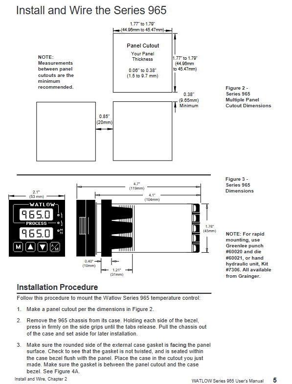
Panel incision size: 55mm (width) × 55mm (height), panel thickness 1.5-9.7mm, fixed with snap on installation ring, ensuring that the sealing gasket is not twisted and installed in place to achieve IP65 protection.
Environmental restrictions: Operating temperature 0-65 ° C, storage temperature -40-85 ° C, relative humidity 0-90% (no condensation), suitable for industrial general environments.
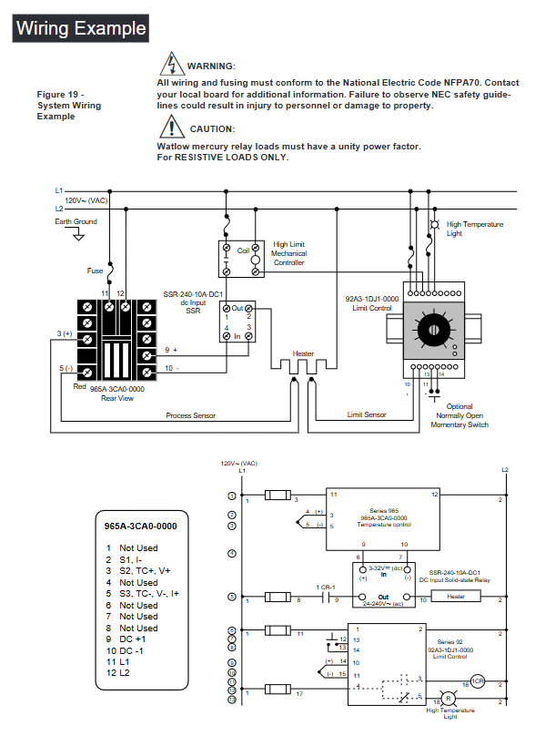
(2) Wiring specifications
Power wiring: Supports 100-240V AC (high voltage type) or 12-24V AC/DC (low voltage type), with built-in slow melting fuses (high voltage type 1A, low voltage type 2A), and must comply with NEC electrical standards.
Input wiring:
Thermocouple: The extension wire should be made of the same material as the thermocouple, and the positive and negative poles should be distinguished (red is usually the negative pole) to avoid polarity reversal.
RTD: The 3-wire system can compensate for lead resistance, and the three leads need to have the same specifications (same wire diameter, same length). If the total lead resistance is too high, it will cause measurement errors.
Process signal: 0-5V input impedance of 10k Ω, 4-20mA input impedance of 5 Ω, ensuring that the signal source and controller are grounded together.
Output wiring: Inductive loads (such as relay coils) need to be paired with RC suppressors (Watlow part number 0804-0147-0000) to avoid electromagnetic interference causing equipment damage.
Operation and Configuration
(1) Menu Structure and Navigation
Menu Type Entry Method Core Functions
Operation menu: Press the MODE key to switch and adjust settings, PID parameters, alarm thresholds, start self-tuning, etc
Simultaneously press and hold the up and down arrow keys for 3 seconds in the setup menu to configure input types, output functions, alarm logic, lock levels, slope parameters, etc
Calibration Menu: Continue to long press the up and down arrow keys from the settings menu to input/output calibration, restore factory calibration values, and switch between US/SI unit systems
(2) Core configuration steps
Input type configuration: Open the controller chassis and select the input type (thermocouple/RTD/process signal) through the internal DIP switch. It should be consistent with the In parameter in the settings menu, otherwise an error will be triggered.
Self tuning start: Set the AUt parameter (1=slow/2=medium/3=fast) in the operation menu, press the MODE key to start, and during the self-tuning process, the display screen alternately displays "At" and normal information. After completion, the optimal PID parameters are automatically saved.
Alarm configuration: Set the Ot2 parameter in the settings menu to select the alarm type (process/deviation), configure parameters such as ALO (low alarm threshold), AHI (high alarm threshold), HSA (hysteresis), LAt (lockout mode), etc.
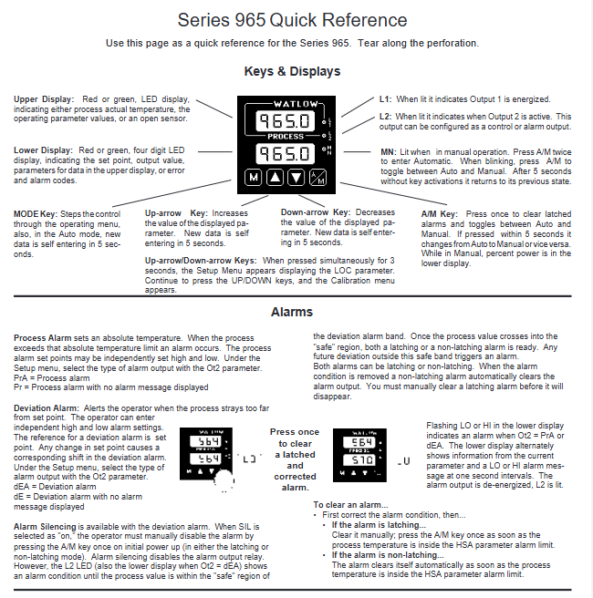
(3) Keys and Display
Key functions: The MODE key is used to switch menus, the up and down arrow keys adjust parameter values (long press to quickly increase or decrease), and the A/M key is used to switch between automatic/manual modes and clear lock alarms.
Display screen: The upper screen displays the process value (PV), the lower screen displays the set value (SP)/parameter name/alarm/error code, flashes "LO"/"HI" when an alarm occurs, and displays "----" when a sensor fails.
Troubleshooting and Maintenance
(1) Handling common error codes
Steps for handling error code reasons
Er2 RTD under range or A/D circuit fault check RTD wiring and resistance value, confirm input type configuration matches
Er4 microprocessor configuration error. Contact the manufacturer for after-sales repair
Er5 non-volatile memory verification error, power off and restart. If it is invalid, contact the manufacturer to replace the memory
Er6/Er7 A/D conversion overflow/undercurrent check sensor wiring (open circuit/reverse polarity), confirm that the input type is consistent with the DIP switch
(2) Maintenance points
Regular calibration: It is recommended to calibrate the input/output accuracy once a year, using precision millivolt sources, resistance boxes, and other equipment. Before calibration, the current parameters should be recorded.
Terminal maintenance: Check the tightness of the wiring to avoid poor contact caused by vibration. The lifespan of mechanical relays is about 100000 cycles, and it is recommended to use solid-state relays for high-frequency switching.
Noise protection: The input signal line should be separated from the power line (with a minimum distance of 305mm), using shielded wire/twisted pair, and inductive loads should be paired with RC suppressors.
- YOKOGAWA
- Reliance
- ADVANCED
- SEW
- ProSoft
- WATLOW
- Kongsberg
- FANUC
- VSD
- DCS
- PLC
- man-machine
- Covid-19
- Energy and Gender
- Energy Access
- Renewable Integration
- Energy Subsidies
- Energy and Water
- Net zero emission
- Energy Security
- Critical Minerals
- A-B
- petroleum
- Mine scale
- Sewage treatment
- cement
- architecture
- Industrial information
- New energy
- Automobile market
- electricity
- Construction site
- HIMA
- ABB
- Rockwell
- Schneider Modicon
- Siemens
- xYCOM
- Yaskawa
- Woodward
- BOSCH Rexroth
- MOOG
- General Electric
- American NI
- Rolls-Royce
- CTI
- Honeywell
- EMERSON
- MAN
- GE
- TRICONEX
- Control Wave
- ALSTOM
- AMAT
- STUDER
- KONGSBERG
- MOTOROLA
- DANAHER MOTION
- Bentley
- Galil
- EATON
- MOLEX
- Triconex
- DEIF
- B&W
- ZYGO
- Aerotech
- DANFOSS
- KOLLMORGEN
- Beijer
- Endress+Hauser
- schneider
- Foxboro
- KB
- REXROTH
- YAMAHA
- Johnson
- Westinghouse
- WAGO
- TOSHIBA
- TEKTRONIX
- BENDER
- BMCM
- SMC
- HITACHI
- HIRSCHMANN
- XP POWER
- Baldor
- Meggitt
- SHINKAWA
- Other Brands
- UniOP
- KUKA
- IBA
- Beckhoff
-
ADLINK CPCI-6860A - 51-31310-OB10 industrial motherboard CompactPCI SBC
-
ADLINK AmITX-SL-G-H110 - 51-7A104-0A30 Mini-ITX Industrial Motherboard
-
ADLINK PXI-2005-003 - CPCI Industrial PC Data Acquisition Card Multi-Function DAQ
-
ADLINK DININ-814M - 51-14032-0A3D SCSI-100P cable connection Interface Terminal Board
-
ADLINK CPCI-3920NA/C2D15/M1G - 3U CompactPCI Intel Core 2 Duo Single Board Computer
-
ADLINK PCIE-8560 - 51-18014-0A20 Communication Card High Speed DAQ
-
ADLINK PCI-C154+ - Motion Control Card 4-axis Motion Controller Board
-
ADLINK PCI-RTV24 - image capture card Analog Video Frame Grabber
-
ADLINK NuPRO-842LV/P - 51-41360-0B30 Industrial Motherboard CPU Board
-
ADLINK cBP-3208/3208R - CPCI Board 3U 8-Slot CompactPCI Backplane
-
ADLINK PCI-8164 - 4-Axis Motion Controller PCI Card 51-12406-0A40
-
ADLINK PCIe-GIE64+ - 4-CH GigE Vision PoE+ Frame Grabber Video Capture Card
-
ADLINK CPCI-6860 / 6860A - CompactPCI Dual Xeon Single Board Computer
-
ADLINK IEC-915GV - REV 1.1 Industrial motherboard CPU Board
-
ADLINK ND-6520 - Technology RS-232 to RS-422RS-485 Converter NuDAM Module
-
ADLINK RTV-24 / PCI-MP4S - 51-12519-1C30 4-Channel Real Time Video Capture Board
-
ADLINK cPCI-6910 / cPCI-6910AM/M1G - cPCI-6910AM/DXL16/M1G/S80G(G)-3120 BOARD CompactPCI SBC
-
ADLINK NUPRO-A40H - Linghua 51-41807-1A30 Industrial Control Computer Motherboard
-
ADLINK USB-3488A - USB to GPIB INTERFACE USB-3488A(G) Controller Module
-
ADLINK PCI-8134A - motion control card 4-Axis Controller Card
-
ADLINK PCI-7432 - Board 32-Channel input / 32-output Isolated Digital I/O PCI Card
-
ADLINK PCI-8134A - 51-12421-0A10 motion controller card tested
-
ADLINK LPCIe-7230 - 32 CH Isolated Input/output Card 2 Interrupts Low Profile PCIe
-
ADLINK NuPRO-E340 - industrial computer motherboard 51-47807-0A30 PICMG 1.3 SHB
-
ADLINK PCI-7434 - High-speed Digital Acquisition Card 64-CH Isolated DO Card
-
ADLINK NuPRO-E330 - 51-41805-0A20 Indsutrial Board SHB Single Board Computer
-
ADLINK PCI-7248 - OPTO-22 48 CHANNEL DIO DIGITAL TTL/DTL I/O 51-12006-0A40 GP
-
ADLINK PCI-8134 - Motion control card 4-Axis Controller Card
-
ADLINK AMP-208C - Movimiento Control Tarjeta 51-12420-1A20 W/Expansión & Breakout
-
ADLINK PCI-8164 - 51-12406-0A40 PCB Board 4-Axis Motion Controller Card
-
ADLINK DIN-68Y-SGII / DIN-68M-J3A - Terminal Board Connector Interface Block
-
ADLINK PCIe-7432 - Technology 51-18402-0A10 PCIe Card With High Input Range
-
ADLINK PCI-8144 / PCI-8144N - Motion control card 4-Axis Stepper Controller Card
-
ADLINK HSL-HUB3/REPEATER - HIGH SPEED LINK EXTENSION MODULES Distributed Hub Module
-
ADLINK ND-6017 - Data Logging + Acquisition 8CH A/D input Mod NuDAM Module
-
ADLINK LPCIe-7250 - data acquisition card Low Profile 8-CH Relay Output Card
-
ADLINK PCI-7432 - I/O card 64-CH Isolated Digital Input Output PCI Card
-
ADLINK IMB-M43H - industrial control computer motherboard Q87 Chip Micro-ATX
-
ADLINK MP-C154 - Motion control Card 4-Axis Motion Controller Board
-
ADLINK PCI-RTV24 - image capture card Video Frame Grabber Card
-
ADLINK PCI-7250 - 8-CH Relay Output & 8-CH Isolated DI Card
-
ADLINK PCI-6308V - 8-CH 12-Bit Isolated Analog Output PCI Card PCB-I-E-1148=6EX2
-
ADLINK PCI-7248 - capture card 48-CH Opto-22 Compatible DIO Card
-
ADLINK HSL-AI16A02-M-VV - Analog Input Output Distributed Module
-
ADLINK NuPRO-A301 - Rev:1.4 NUPRO-A301 PICMG Full-Size Single Board Computer
-
ADLINK PCI-6208V-GL - 8-CH Voltage Analog Output PCI Card
-
ADLINK PCI-8134A - 51-12421-0A10 4-Axis Motion Controller Card
-
ADLINK MNET-S23 - TECHNOLOGY MNET S23 - SERVO DRIVER CONTROL MODULE
-
ADLINK M-342 - ATX I3 I5 I7 Q67 Industrial Motherboard
-
ADLINK NUPRO-780 - Industrial Motherboard CPU Board PICMG SBC
-
ADLINK MP-C154 / MP-C152 - 4-Axis Motion Control Card Pulse-Train Controller
-
ADLINK NuPRO-935A/LV10B0 - Motherboard 51-41802-0A10 GP w/RAM Industrial Control Board
-
ADLINK MP-C154 - Motion control card 4-Axis Motion Controller Mainboard
-
ADLINK PCI-7250 - PCI Acquisition Card 8-CH Relay Output Isolated DI Card
-
ADLINK ACL-7124 - Technology Inc.24 DIO Card Digital Input Output Card
-
ADLINK PCI-8554 A2 - Timer/Counter Data Acquisition Card
-
ADLINK DIN-825-GP4 - Terminal Block Interface Board Breakout Module
-
ADLINK NuPR0-761 - REV:1.1 Industrial motherboard Full-Size PICMG SBC
-
ADLINK MXE-1401/M8G (G) - Matrix Fanless Embedded Computer Industrial PC
-
ADLINK HSL-DI16DO16-UD-NN - Digital 16 Channel I/O Mod Distributed I/O Module
-
ADLINK ND6520 - NUDAM INTELLIGENT DA&C MODULE RS232-RS-422/RS485 CONVERTOR
-
ADLINK NUPRO-761 - REV:1.1 Industrial Motherboard CPU Board
-
ADLINK AMP-208C - Motion Control Card 51-12420-1A20 DSP-based 8-axis
-
ADLINK NuPRO-A301REV 1.4 - with packaging industrial computer motherboard PICMG SBC
-
ADLINK PCM-9112+ - 51-12300-0A2 industrial motherboard Multi-Function DAQ PC/104 Module
-
ADLINK PCM-7250+ - 8-CH Relay Outputs & 8-CH Isolated DI Module PC/104
-
ADLINK PCI-RTV24 - Image capture card Analog Video Frame Grabber
-
ADLINK PCI-8134 - Motion Controller PCI Card 4-Axis Controller Board
-
ADLINK PCI-7432 - Isolated Digital I/O PCI Card
-
ADLINK PCI-8554 A2 - acquisition card Timer/Counter Card
-
ADLINK PCI-8132 - Rev.A2 2-Axis Servo & Stepper Motion Controller Card
-
ADLINK PCI-8132 - Data Acquisition card 2-Axis Motion Controller Card
-
ADLINK EBP-13E4 - 51-46703-0A30 Industrial Backplane Board Passive Backplane
-
ADLINK PCI-800L - Electronic Card Interface Controller Card
-
ADLINK PCIe-GIE72 - 51-18531-0A10 PCB Board GigE Vision Frame Grabber
-
ADLINK DAQ-2010(G)-OOBO - Simultaneous-Sampling Multi-Function DAQ Card
-
ADLINK PCI-9112 - REV.B1 Multifunction DAQ Card Data Acquisition Card
-
ADLINK PCI-7230 - 51-12003-DA60 32-CH Isolated Digital I/O Card
-
ADLINK PCI-7432 - Data Acquisition Card Isolated Digital I/O PCI Card
-
ADLINK ETX-AT-N270-18/LXE - 51-71111-0A20 ETX CPU Module Motherboard
-
ADLINK HSL-DI32-UD-N - DIGITAL INPUT 32 POINTS MODULE Distributed I/O
-
ADLINK AMP-204C - Motion Control card DSP-Based 4-Axis Advanced Controller
-
ADLINK MNET-4XMOG-0050 - Four-axis Motion Controller Distributed Motion Module
-
ADLINK AMP-204C - Motion control card DSP-Based 4-Axis Pulse-Train Controller
-
ADLINK PCI-7442 - Switch card 64-Channel Datalogging & Acquisition Card
-
ADLINK M-302 - Industrial control motherboard ATX PC Board
-
ADLINK NUPRO-852 / NUPRO-852LV - Industrial motherboard Single Board Computer
-
ADLINK PCI-8134 - REV.B1. 4-Axis Motion Controller Card
-
ADLINK PCI-GIE62 + - 51-18502-0A20 2-CH GigE Vision Frame Grabber PoE Card
-
ADLINK PCI-MPG24 - 51-12523-0B20 MPEG4 Card Video Compression Hardware
-
ADLINK HSL-TB32-M-DIN - 32-CH I/O TERMINAL W/ HSL-AI16AO2-M-VV MODULE
-
ADLINK PCI-M114-GL - PCB Ver 2.1 Motion Controller Axis Card
-
ADLINK IMB-M40H - SYM76996H61 motherboard Industrial Computer Mainboard
-
ADLINK NUPRO-A40H - 51-41807-1A20 industrial control motherboard H61 Chip
-
ADLINK PCI-M114-GL - Axis Card Data Acquisition Card PCB VER2.2 Motion Controller
-
ADLINK PCI-8134 - Motion Controller PCI Card 4-Axis Controller Board
-
ADLINK PCI-8102 - Motion control card 2-Axis Servo & Stepper Controller
-
ADLINK NuPRO-841REV:3.0 - motherboard Industrial Control PC Board
-
ADLINK HSL-TB32-U-DIN REV A1 - Breakout Terminal Board Field I/O Module
-
ADLINK AMP-204C - Motion Control card DSP-Based 4-Axis Pulse-Train Controller
-
ADLINK NUPRO-A40H - 51-41807-1A20 industrial control motherboard H61 PC Board
-
ADLINK PCI-6308A / PCI-6308V - 51-12202-0A50 Isolated Analog Output Card
-
ADLINK AMP-204C - DSP-Based 4-Axis Advanced Pulse-Train Motion Controller
-
ADLINK PCI-7434 - Technology 64-Channel Isolated Digital I/O PCI Cards
-
ADLINK CPCI-6840 / CPCI-6840V / PM16/M1G-12G0 - CompactPCI Single Board Computer CPU Module
-
ADLINK PCIE-GIE74 - Motherboard Video Capture Card 51-18531-0A10 Frame Grabber
-
ADLINK NuPRO-E330 - industrial computer equipment motherboard Control Mainboard
-
ADLINK AMP-208C / 51-12420-1A20 - Motion Control Card W/ Expansion & Breakout Board
-
ADLINK HPCI-14S12U - industrial computer baseboard Passive Backplane 14 Slots
-
ADLINK PCI-8164 - 4-Axis Motion Controller PCI Card W/ 1x Cable, 1x Breakout Box
-
ADLINK PCIe-RTV24 - 51-18016-0A20 Image Acquisition Video Capture Card
-
ADLINK M-342 - 5 PCI ATX Motherboard Industrial PC Mainboard
-
ADLINK PCI-FIW64 - 4/2 Channel IEEE1394B Image Capture Card FireWire Frame Grabber
-
ADLINK PCI-7432 - digital IO card 64-CH Isolated Digital Input Output Card
-
ADLINK 51-12001-0C20 - Circuit Board PCI-7200 Data Acquisition Controller Card
-
ADLINK PXI-3920 - PXI 3U cPCI Industrial Controller Embedded System CPU Board
-
ADLINK NuPRO-841REV:2.0 - motherboard Industrial Control PC Board
-
ADLINK NuPro-E330 - 51-41805-0A20 PCB Industrial Control Computer Motherboard
-
ADLINK PCI-RTV24 - Image capture card Analog Video Frame Grabber
-
ADLINK PCI-7442 - Switch card 64-Channel Datalogging & Acquisition Card
-
ADLINK HPX-13S4 - device baseboard Passive Backplane Riser Card
-
ADLINK PCI-9112 REV A.1 - Multi Function DA&C Board Data Acquisition Card
-
ADLINK PCI-7248 - 51-12006-0A40 Card Control 48-CH Digital I/O Module
-
ADLINK CPCI-6860 / 6860A - motherboard CompactPCI Dual Xeon Single Board Computer
-
ADLINK DPAC-3020-11(G) - Embedded PC Automation Controller Machine Control Board
-
ADLINK NuPRO-841 REV:1.0 - industrial control motherboard CPU Board
-
ADLINK MNET-4XMOG-0050 - Four-axis Motion Controller MNET Motion Control Card
-
ADLINK ETX-AT-N270-18/LXE - 51-71111-0A20 ETX CPU Module Motherboard

K-JIANG

Add: Jimei North Road, Jimei District, Xiamen, Fujian, China
Tell:+86-15305925923