
K-WANG


Tektronix TBS1000B and TBS1000B-EDU series digital storage oscilloscopes
Tektronix TBS1000B and TBS1000B-EDU series digital storage oscilloscopes
Document Overview
This manual is the official guidance document for the Tektronix TBS1000B (General Edition) and TBS1000B-EDU (Education Edition) series of digital storage oscilloscopes, covering the entire process of product safety operation to advanced functional applications. It is suitable for engineers, technicians, and teachers and students in educational settings. The manual has a clear structure and includes modules such as safety information, basic operations, core functions, application cases, performance parameters, and probe information. At the same time, through tables, diagrams, and step-by-step instructions, it reduces operational complexity and ensures that users can quickly master the use and maintenance of the oscilloscope.
Product model and core parameters
1. Model classification and key parameters
Applicable scenarios for model bandwidth sampling rate
TBS1032B 30MHz 500MS/s Basic Low Frequency Measurement (North America/Europe only)
TBS1052B/TBS1052B-EDU 50MHz 1GS/s Universal Low Frequency Testing and Educational Experiment
Analysis of Low Frequency Signals in TBS1072B/TBS1072B-EDU 70MHz 1GS/s
TBS1102B/TBS1102B-EDU 100MHz 2GS/s High Frequency Digital Signal Test
TBS1152B/TBS1152B-EDU 150MHz 2GS/s High Speed Serial Signal Analysis
TBS1202B/TBS1202B-EDU 200MHz 2GS/s ultra high speed signal (such as DDR memory) testing
2. General core features
Channel configuration: 2 analog channels, supporting simultaneous measurement of 2 signals
Record length: fixed 2500 points/channel to ensure complete signal details
Display screen: 7-inch color LCD, supporting vector/dot display mode
Measurement function: 34 types of automatic measurement, cursor measurement, FFT spectrum analysis
Storage interface: front USB flash drive port (supporting ≤ 64GB), rear USB device port (connected to PC/GPIB)
Language support: 11 languages (including Chinese, English, Japanese, Korean, Russian, etc.)
Safety operation standards
1. Electrical safety
Grounding requirements: A 3-pin power cord must be used, and the grounding conductor must be connected to the ground. It is forbidden to disconnect the grounding
Voltage limitation: The maximum voltage of the input channel is 300V RMS CAT II, and when it exceeds 100kHz, it attenuates by 20dB/tenfold
Probe safety: When using TPP series probes, fingers should be placed behind a protective barrier and touching the metal parts of the probe is prohibited
2. Operation taboos
Prohibited from use in damp/explosive environments, avoid liquid spraying equipment
It is prohibited to dismantle the equipment casing as high internal voltage may cause electric shock
When connecting/disconnecting the probe, the signal source should be disconnected first to avoid arc damage
Basic operation process
1. Equipment installation and functional inspection
Power connection: Connect to a 90-264VAC/45-66Hz power supply, with a maximum power consumption of 30W
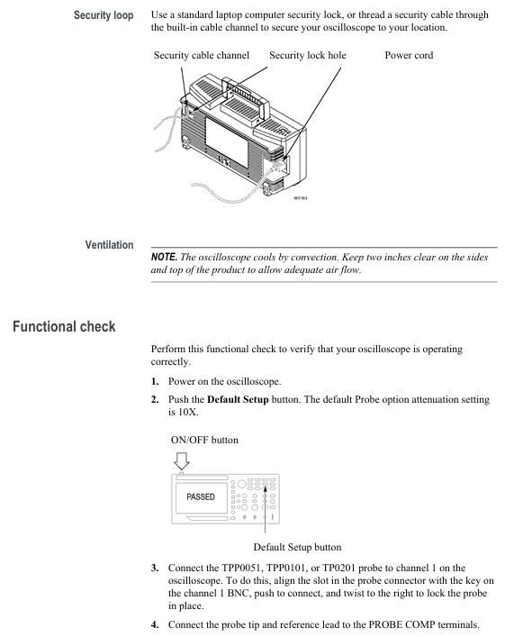
Secure fixation: Fix equipment through safety lock holes or cable channels to prevent slipping
Functional check:
Press' Default Setup 'to restore factory settings
Connect the probe to CH1, and connect the probe tip to the PROBE COMP terminal( 5V@1kHz Square wave
Press [Autoset], the screen should display a stable square wave, and the calibration status should be "PASSED"
2. Probe operation
Manual compensation:
Probe connected to CH1, set attenuation to 10X
Connect the probe tip to [PROBE COMP] and press [Autoset]
Adjust the probe compensation hole to make the square wave edge straight (to avoid overcompensation/undercompensation)
Attenuation setting: default 10X, P2220 probe supports 1X/10X switching (bandwidth limited to 6MHz at 1X)
Current probe: The scaling ratio needs to be manually set (default 10A/V) to ensure accurate readings
3. Self calibration and firmware updates
Self calibration:
Trigger condition: If the environmental temperature difference exceeds 5 ℃ or once a week, preheating for 20 minutes is required
Operation steps: Disconnect all probes → 【 Utility 】 → 【 Do Self Cal 】 → Follow the prompts to complete (about 2 minutes)
Firmware update:
Download the latest firmware from the official website (www.tektronix. com/software)
Copy to the root directory of the USB flash drive and insert the oscilloscope
[Utility] → [File Utilities] → [Update Firmware] → Wait for completion
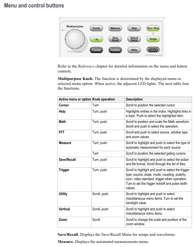
Core System and Control
1. Vertical Controls
Coupling method:
DC: Transmitting AC+DC signals, suitable for measuring signals with DC offset
AC: Block DC components, suitable for observing AC signals
GND: Disconnect input, display 0V line, used for calibrating ground reference
Bandwidth limit: 20MHz bandwidth limit can be selected to reduce high-frequency noise
Voltage/grid adjustment: Range 2mV-5V/div, supports coarse adjustment (1-2-5 sequence)/fine adjustment (small step size)
2. Horizontal Controls
Time base range:
30MHz model: 10ns-50s/div
50/70MHz model: 5ns-50s/div
100/150/200MHz model: 2.5ns-50s/div
Scanning mode: automatically turned on when the time base is ≥ 100ms/div and the trigger mode is "Auto", and the waveform scrolls from left to right
Zoom function: Press [Zoom] to zoom in on specific parts of the waveform, supporting X1/X2/X5/X10 zoom ratios
3. Trigger Controls
Trigger type key parameters applicable scenarios
Edge triggered slope (rising/falling), coupling (AC/DC/noise suppression), stable display of conventional signals (sine wave/square wave)
Video trigger standards (NTSC/PAL/SECAM), synchronous (field/line) composite video signal testing, such as television signals
Pulse width triggering conditions (=≠<>), width (33ns-10s), polarity (positive/negative) capture abnormal pulses (such as spikes, narrow pulses)
Trigger mode:
Auto: Automatically scans without triggering, suitable for signal exploration
Normal: Only displayed when triggered, suitable for stable signal observation
Single: Single capture, suitable for transient signals (such as relay arcs)
4. Acquisition Controls
The working principle of the collection mode is applicable to different scenarios
Sampling mode equidistant sampling, 1 sampling point=1 waveform point for most conventional signals
Peak detection mode records the maximum/minimum values within each interval, captures narrow pulses (≥ 10ns), and reduces aliasing
After multiple acquisitions in average mode (4/16/64/128 times optional), suppress random noise and improve signal clarity
Measurement and analysis functions
1. Basic measurement techniques
Voltage measurement:
Peak to Peak Value (Vp-p): The difference between the maximum and minimum values of the signal, calculated by multiplying the number of vertical partitions by volts per grid and the probe attenuation ratio
Amplitude: Voltage from ground to signal peak, for example: 2V/div x 3 zones x 10X probe=60V
Time measurement:
Cycle/frequency: Cycle=number of horizontal partitions x seconds/grid, frequency=1/cycle
Pulse width: time interval at 50% amplitude, rise/fall time: time interval at 10% -90% amplitude
Phase difference measurement: Turn on XY mode and use the Lissajous diagram to determine (for example, when the frequency ratio is 1:1, the straight line is 0 ° and the circle is 90 °)
2. Automatic measurement and FFT analysis
Automatic measurement:
Supports 34 types, including time class (cycle, frequency, delay), amplitude class (peak to peak, overshoot), and count class (pulse number, edge number)
Up to 6 measurement results can be displayed simultaneously, with an update frequency of approximately 2 times per second
FFT analysis:
Window function selection: Hanning window (excellent frequency resolution), flat top window (excellent amplitude accuracy), rectangular window (transient analysis)
Nyquist frequency: half of the sampling rate. Exceeding this frequency will result in aliasing, which needs to be resolved by increasing the sampling rate or filtering
Spectrum measurement: supports cursor measurement of frequency (Hz) and amplitude (dB, 0dB=1VRMS)
Data storage and transmission
1. USB flash drive operation
Storage content and capacity (approximately per 1MB):
250 setup files (. SET)
18 waveform files (. CSV, containing 2500 point time amplitude data)
16 image files (BMP/JPG)
Key operations:
Save: [Save/Recall] ->Select "Save Image/Set/Waveform" ->Automatic Naming (e.g. TEK0000. BMP)
Recall: [Save/Recall] → Select "Recall Setup/Waveform" → Select file
Format: [Utility] → [File Utilities] → [Format], note to delete all data
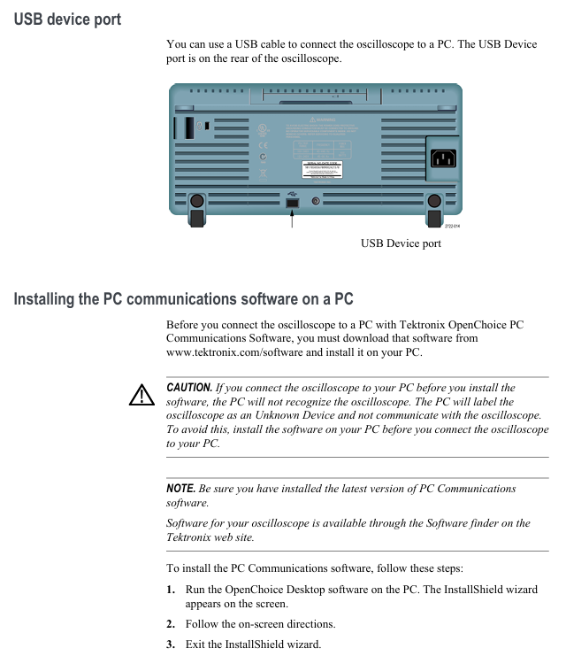
2. Connection between PC and GPIB
PC connection:
Install OpenChoice software (official website download)
Connect the USB cable between the oscilloscope's rear USB device port and the PC
Install the driver as prompted, supporting waveform transmission and remote control
GPIB connection:
Connect oscilloscope and GPIB controller through TEK-USB-488 adapter
[Utility] → [GPIB Setup] Set address (default 1)
Run GPIB software to achieve multi device collaborative control
Application Cases (Selected)
1. Video signal testing
Connect the probe to the video output and set the coupling to AC
【 Trigger Menu 】 → Select 'Video' → Set standard to NTSC
Select "All Fields" or "Line Number" synchronously, and press [Autoset]
Adjust the time base to 500ns/div and observe the video line signal (including color synchronization signal)
2. Differential signal analysis
CH1 is connected to the positive terminal of the differential signal, CH2 is connected to the negative terminal, and the probes are both set to 10X
【 Math 】 → Select "Ch1-Ch2" to display the differential waveform
【 Acquire 】 → Set to 'Peak Detect' to capture signal overshoot/noise
Read differential signal amplitude and rise time using automatic measurement function
3. Education version course application (exclusive to EDU version)
Create a course on PC (download specialized software) and save it as an. xpkg file
Insert the USB flash drive into the oscilloscope, go to 【 Utility 】 → 【 Update Course 】 → Load Course
Select the experiment according to 'Course' and view the steps and theories
After completing the experiment, the Data Collection saves the data and generates a report containing waveforms
Appendix and Maintenance
1. Performance parameters (key)
Vertical system: resolution 8-bit, DC gain accuracy ± 3% (10mV-5V/div), input impedance 1M Ω//20pF
Horizontal system: Time base accuracy of 50ppm, maximum delay scanning of 100 partitions
Trigger system: Edge trigger sensitivity ≤ 1mV (50Hz bandwidth), pulse width trigger minimum 33ns
Environmental adaptability: Working temperature 0-50 ℃, humidity ≤ 85% (below 40 ℃)
2. Probe information (TPP series)
Model bandwidth attenuation ratio compensation range, maximum input voltage
TPP0051 50MHz 10:1 15-25pF 300V RMS CAT II
TPP0101 100MHz 10:1 15-25pF 300V RMS CAT II
TPP0201 200MHz 10:1 15-25pF 300V RMS CAT II
3. Equipment maintenance
Cleaning: Use a lint free cloth dipped in 75% isopropanol to wipe the outer shell, avoiding the use of abrasion cleaner
Calibration: It is recommended to conduct factory calibration annually and contact the Tech service center
Troubleshooting: Check the error log through 【 Utility 】 → 【 System Status 】. Common issues include probe not compensating and improper trigger settings
- YOKOGAWA
- Reliance
- ADVANCED
- SEW
- ProSoft
- WATLOW
- Kongsberg
- FANUC
- VSD
- DCS
- PLC
- man-machine
- Covid-19
- Energy and Gender
- Energy Access
- Renewable Integration
- Energy Subsidies
- Energy and Water
- Net zero emission
- Energy Security
- Critical Minerals
- A-B
- petroleum
- Mine scale
- Sewage treatment
- cement
- architecture
- Industrial information
- New energy
- Automobile market
- electricity
- Construction site
- HIMA
- ABB
- Rockwell
- Schneider Modicon
- Siemens
- xYCOM
- Yaskawa
- Woodward
- BOSCH Rexroth
- MOOG
- General Electric
- American NI
- Rolls-Royce
- CTI
- Honeywell
- EMERSON
- MAN
- GE
- TRICONEX
- Control Wave
- ALSTOM
- AMAT
- STUDER
- KONGSBERG
- MOTOROLA
- DANAHER MOTION
- Bentley
- Galil
- EATON
- MOLEX
- Triconex
- DEIF
- B&W
- ZYGO
- Aerotech
- DANFOSS
- KOLLMORGEN
- Beijer
- Endress+Hauser
- schneider
- Foxboro
- KB
- REXROTH
- YAMAHA
- Johnson
- Westinghouse
- WAGO
- TOSHIBA
- TEKTRONIX
- BENDER
- BMCM
- SMC
- HITACHI
- HIRSCHMANN
- XP POWER
- Baldor
- Meggitt
- SHINKAWA
- Other Brands
- UniOP
- KUKA
- IBA
- Beckhoff
-
ADLINK CPCI-6860A - 51-31310-OB10 industrial motherboard CompactPCI SBC
-
ADLINK AmITX-SL-G-H110 - 51-7A104-0A30 Mini-ITX Industrial Motherboard
-
ADLINK PXI-2005-003 - CPCI Industrial PC Data Acquisition Card Multi-Function DAQ
-
ADLINK DININ-814M - 51-14032-0A3D SCSI-100P cable connection Interface Terminal Board
-
ADLINK CPCI-3920NA/C2D15/M1G - 3U CompactPCI Intel Core 2 Duo Single Board Computer
-
ADLINK PCIE-8560 - 51-18014-0A20 Communication Card High Speed DAQ
-
ADLINK PCI-C154+ - Motion Control Card 4-axis Motion Controller Board
-
ADLINK PCI-RTV24 - image capture card Analog Video Frame Grabber
-
ADLINK NuPRO-842LV/P - 51-41360-0B30 Industrial Motherboard CPU Board
-
ADLINK cBP-3208/3208R - CPCI Board 3U 8-Slot CompactPCI Backplane
-
ADLINK PCI-8164 - 4-Axis Motion Controller PCI Card 51-12406-0A40
-
ADLINK PCIe-GIE64+ - 4-CH GigE Vision PoE+ Frame Grabber Video Capture Card
-
ADLINK CPCI-6860 / 6860A - CompactPCI Dual Xeon Single Board Computer
-
ADLINK IEC-915GV - REV 1.1 Industrial motherboard CPU Board
-
ADLINK ND-6520 - Technology RS-232 to RS-422RS-485 Converter NuDAM Module
-
ADLINK RTV-24 / PCI-MP4S - 51-12519-1C30 4-Channel Real Time Video Capture Board
-
ADLINK cPCI-6910 / cPCI-6910AM/M1G - cPCI-6910AM/DXL16/M1G/S80G(G)-3120 BOARD CompactPCI SBC
-
ADLINK NUPRO-A40H - Linghua 51-41807-1A30 Industrial Control Computer Motherboard
-
ADLINK USB-3488A - USB to GPIB INTERFACE USB-3488A(G) Controller Module
-
ADLINK PCI-8134A - motion control card 4-Axis Controller Card
-
ADLINK PCI-7432 - Board 32-Channel input / 32-output Isolated Digital I/O PCI Card
-
ADLINK PCI-8134A - 51-12421-0A10 motion controller card tested
-
ADLINK LPCIe-7230 - 32 CH Isolated Input/output Card 2 Interrupts Low Profile PCIe
-
ADLINK NuPRO-E340 - industrial computer motherboard 51-47807-0A30 PICMG 1.3 SHB
-
ADLINK PCI-7434 - High-speed Digital Acquisition Card 64-CH Isolated DO Card
-
ADLINK NuPRO-E330 - 51-41805-0A20 Indsutrial Board SHB Single Board Computer
-
ADLINK PCI-7248 - OPTO-22 48 CHANNEL DIO DIGITAL TTL/DTL I/O 51-12006-0A40 GP
-
ADLINK PCI-8134 - Motion control card 4-Axis Controller Card
-
ADLINK AMP-208C - Movimiento Control Tarjeta 51-12420-1A20 W/Expansión & Breakout
-
ADLINK PCI-8164 - 51-12406-0A40 PCB Board 4-Axis Motion Controller Card
-
ADLINK DIN-68Y-SGII / DIN-68M-J3A - Terminal Board Connector Interface Block
-
ADLINK PCIe-7432 - Technology 51-18402-0A10 PCIe Card With High Input Range
-
ADLINK PCI-8144 / PCI-8144N - Motion control card 4-Axis Stepper Controller Card
-
ADLINK HSL-HUB3/REPEATER - HIGH SPEED LINK EXTENSION MODULES Distributed Hub Module
-
ADLINK ND-6017 - Data Logging + Acquisition 8CH A/D input Mod NuDAM Module
-
ADLINK LPCIe-7250 - data acquisition card Low Profile 8-CH Relay Output Card
-
ADLINK PCI-7432 - I/O card 64-CH Isolated Digital Input Output PCI Card
-
ADLINK IMB-M43H - industrial control computer motherboard Q87 Chip Micro-ATX
-
ADLINK MP-C154 - Motion control Card 4-Axis Motion Controller Board
-
ADLINK PCI-RTV24 - image capture card Video Frame Grabber Card
-
ADLINK PCI-7250 - 8-CH Relay Output & 8-CH Isolated DI Card
-
ADLINK PCI-6308V - 8-CH 12-Bit Isolated Analog Output PCI Card PCB-I-E-1148=6EX2
-
ADLINK PCI-7248 - capture card 48-CH Opto-22 Compatible DIO Card
-
ADLINK HSL-AI16A02-M-VV - Analog Input Output Distributed Module
-
ADLINK NuPRO-A301 - Rev:1.4 NUPRO-A301 PICMG Full-Size Single Board Computer
-
ADLINK PCI-6208V-GL - 8-CH Voltage Analog Output PCI Card
-
ADLINK PCI-8134A - 51-12421-0A10 4-Axis Motion Controller Card
-
ADLINK MNET-S23 - TECHNOLOGY MNET S23 - SERVO DRIVER CONTROL MODULE
-
ADLINK M-342 - ATX I3 I5 I7 Q67 Industrial Motherboard
-
ADLINK NUPRO-780 - Industrial Motherboard CPU Board PICMG SBC
-
ADLINK MP-C154 / MP-C152 - 4-Axis Motion Control Card Pulse-Train Controller
-
ADLINK NuPRO-935A/LV10B0 - Motherboard 51-41802-0A10 GP w/RAM Industrial Control Board
-
ADLINK MP-C154 - Motion control card 4-Axis Motion Controller Mainboard
-
ADLINK PCI-7250 - PCI Acquisition Card 8-CH Relay Output Isolated DI Card
-
ADLINK ACL-7124 - Technology Inc.24 DIO Card Digital Input Output Card
-
ADLINK PCI-8554 A2 - Timer/Counter Data Acquisition Card
-
ADLINK DIN-825-GP4 - Terminal Block Interface Board Breakout Module
-
ADLINK NuPR0-761 - REV:1.1 Industrial motherboard Full-Size PICMG SBC
-
ADLINK MXE-1401/M8G (G) - Matrix Fanless Embedded Computer Industrial PC
-
ADLINK HSL-DI16DO16-UD-NN - Digital 16 Channel I/O Mod Distributed I/O Module
-
ADLINK ND6520 - NUDAM INTELLIGENT DA&C MODULE RS232-RS-422/RS485 CONVERTOR
-
ADLINK NUPRO-761 - REV:1.1 Industrial Motherboard CPU Board
-
ADLINK AMP-208C - Motion Control Card 51-12420-1A20 DSP-based 8-axis
-
ADLINK NuPRO-A301REV 1.4 - with packaging industrial computer motherboard PICMG SBC
-
ADLINK PCM-9112+ - 51-12300-0A2 industrial motherboard Multi-Function DAQ PC/104 Module
-
ADLINK PCM-7250+ - 8-CH Relay Outputs & 8-CH Isolated DI Module PC/104
-
ADLINK PCI-RTV24 - Image capture card Analog Video Frame Grabber
-
ADLINK PCI-8134 - Motion Controller PCI Card 4-Axis Controller Board
-
ADLINK PCI-7432 - Isolated Digital I/O PCI Card
-
ADLINK PCI-8554 A2 - acquisition card Timer/Counter Card
-
ADLINK PCI-8132 - Rev.A2 2-Axis Servo & Stepper Motion Controller Card
-
ADLINK PCI-8132 - Data Acquisition card 2-Axis Motion Controller Card
-
ADLINK EBP-13E4 - 51-46703-0A30 Industrial Backplane Board Passive Backplane
-
ADLINK PCI-800L - Electronic Card Interface Controller Card
-
ADLINK PCIe-GIE72 - 51-18531-0A10 PCB Board GigE Vision Frame Grabber
-
ADLINK DAQ-2010(G)-OOBO - Simultaneous-Sampling Multi-Function DAQ Card
-
ADLINK PCI-9112 - REV.B1 Multifunction DAQ Card Data Acquisition Card
-
ADLINK PCI-7230 - 51-12003-DA60 32-CH Isolated Digital I/O Card
-
ADLINK PCI-7432 - Data Acquisition Card Isolated Digital I/O PCI Card
-
ADLINK ETX-AT-N270-18/LXE - 51-71111-0A20 ETX CPU Module Motherboard
-
ADLINK HSL-DI32-UD-N - DIGITAL INPUT 32 POINTS MODULE Distributed I/O
-
ADLINK AMP-204C - Motion Control card DSP-Based 4-Axis Advanced Controller
-
ADLINK MNET-4XMOG-0050 - Four-axis Motion Controller Distributed Motion Module
-
ADLINK AMP-204C - Motion control card DSP-Based 4-Axis Pulse-Train Controller
-
ADLINK PCI-7442 - Switch card 64-Channel Datalogging & Acquisition Card
-
ADLINK M-302 - Industrial control motherboard ATX PC Board
-
ADLINK NUPRO-852 / NUPRO-852LV - Industrial motherboard Single Board Computer
-
ADLINK PCI-8134 - REV.B1. 4-Axis Motion Controller Card
-
ADLINK PCI-GIE62 + - 51-18502-0A20 2-CH GigE Vision Frame Grabber PoE Card
-
ADLINK PCI-MPG24 - 51-12523-0B20 MPEG4 Card Video Compression Hardware
-
ADLINK HSL-TB32-M-DIN - 32-CH I/O TERMINAL W/ HSL-AI16AO2-M-VV MODULE
-
ADLINK PCI-M114-GL - PCB Ver 2.1 Motion Controller Axis Card
-
ADLINK IMB-M40H - SYM76996H61 motherboard Industrial Computer Mainboard
-
ADLINK NUPRO-A40H - 51-41807-1A20 industrial control motherboard H61 Chip
-
ADLINK PCI-M114-GL - Axis Card Data Acquisition Card PCB VER2.2 Motion Controller
-
ADLINK PCI-8134 - Motion Controller PCI Card 4-Axis Controller Board
-
ADLINK PCI-8102 - Motion control card 2-Axis Servo & Stepper Controller
-
ADLINK NuPRO-841REV:3.0 - motherboard Industrial Control PC Board
-
ADLINK HSL-TB32-U-DIN REV A1 - Breakout Terminal Board Field I/O Module
-
ADLINK AMP-204C - Motion Control card DSP-Based 4-Axis Pulse-Train Controller
-
ADLINK NUPRO-A40H - 51-41807-1A20 industrial control motherboard H61 PC Board
-
ADLINK PCI-6308A / PCI-6308V - 51-12202-0A50 Isolated Analog Output Card
-
ADLINK AMP-204C - DSP-Based 4-Axis Advanced Pulse-Train Motion Controller
-
ADLINK PCI-7434 - Technology 64-Channel Isolated Digital I/O PCI Cards
-
ADLINK CPCI-6840 / CPCI-6840V / PM16/M1G-12G0 - CompactPCI Single Board Computer CPU Module
-
ADLINK PCIE-GIE74 - Motherboard Video Capture Card 51-18531-0A10 Frame Grabber
-
ADLINK NuPRO-E330 - industrial computer equipment motherboard Control Mainboard
-
ADLINK AMP-208C / 51-12420-1A20 - Motion Control Card W/ Expansion & Breakout Board
-
ADLINK HPCI-14S12U - industrial computer baseboard Passive Backplane 14 Slots
-
ADLINK PCI-8164 - 4-Axis Motion Controller PCI Card W/ 1x Cable, 1x Breakout Box
-
ADLINK PCIe-RTV24 - 51-18016-0A20 Image Acquisition Video Capture Card
-
ADLINK M-342 - 5 PCI ATX Motherboard Industrial PC Mainboard
-
ADLINK PCI-FIW64 - 4/2 Channel IEEE1394B Image Capture Card FireWire Frame Grabber
-
ADLINK PCI-7432 - digital IO card 64-CH Isolated Digital Input Output Card
-
ADLINK 51-12001-0C20 - Circuit Board PCI-7200 Data Acquisition Controller Card
-
ADLINK PXI-3920 - PXI 3U cPCI Industrial Controller Embedded System CPU Board
-
ADLINK NuPRO-841REV:2.0 - motherboard Industrial Control PC Board
-
ADLINK NuPro-E330 - 51-41805-0A20 PCB Industrial Control Computer Motherboard
-
ADLINK PCI-RTV24 - Image capture card Analog Video Frame Grabber
-
ADLINK PCI-7442 - Switch card 64-Channel Datalogging & Acquisition Card
-
ADLINK HPX-13S4 - device baseboard Passive Backplane Riser Card
-
ADLINK PCI-9112 REV A.1 - Multi Function DA&C Board Data Acquisition Card
-
ADLINK PCI-7248 - 51-12006-0A40 Card Control 48-CH Digital I/O Module
-
ADLINK CPCI-6860 / 6860A - motherboard CompactPCI Dual Xeon Single Board Computer
-
ADLINK DPAC-3020-11(G) - Embedded PC Automation Controller Machine Control Board
-
ADLINK NuPRO-841 REV:1.0 - industrial control motherboard CPU Board
-
ADLINK MNET-4XMOG-0050 - Four-axis Motion Controller MNET Motion Control Card
-
ADLINK ETX-AT-N270-18/LXE - 51-71111-0A20 ETX CPU Module Motherboard

K-JIANG

Add: Jimei North Road, Jimei District, Xiamen, Fujian, China
Tell:+86-15305925923