
K-WANG
+086-15305925923
Service expert in industrial control field!


Product
Article
NameDescriptionContent
Adequate Inventory, Timely Service
pursuit of excellence


Ship control system
Equipment control system
Power monitoring system
Current position:
新闻动态
newS
Brand
ABB TC820-1 Control I/O Unit
ABB TC820-1 Control I/O Unit
ABB TC820-1 Control I/O Unit
Ambient Conditions,
Operation
Ambient operating conditions refer to the conditions the NTAC-02/
NDIO-02/NAIO-03 module is subjected to when installed for stationary
use.
Air Temperature: 0 to +50°C.
Relative Humidity: 5 to 95%, no condensation allowed. Maximum
allowed relative humidity is 60% in the presence of corrosive gases.
Contamination Levels:
Chemical gases: IEC 721-3-3, Class 3C2
Solid particles: IEC 721-3-3, Class 3S2
Installation Site Altitude: 0 to 2000 m above sea level. If the
installation site is higher than 2000 m above sea level, please contact
your local ABB distributor or office for further information.
Vibration: Max. 0.3 mm (2 to 9 Hz), max. 1 m/s2 (9 to 200 Hz)
sinusoidal (IEC 68-2-6)
Ambient Conditions,
Storage
Ambient storage conditions refer to the conditions the option module is
subjected to during storage in the protective package.
Temperature: -40 to +70°C.
Relative Humidity: Less than 95%, no condensation allowed.
Atmospheric Pressure: 70 to 106 kPa
Vibration: Max. 0.3 mm (2 to 9 Hz), max. 1 m/s2 (9 to 200 Hz)
sinusoidal (IEC 68-2-6)
Shock: Max. 100 m/s2, 11 ms (IEC 68-2-29)
Ambient Conditions,
Transportation
Ambient transportation conditions refer to the conditions the option
module is subjected to during transportation in the protective package.
Temperature: -40 to +70°C
Relative Humidity: Max. 95%, no condensation allowed.
Atmospheric Pressure: 60 to 106 kPa
Vibration: Max. 3.5 mm (2 to 9 Hz), max. 15 m/s2 (9 to 200 Hz)
sinusoidal (IEC 68-2-6)
Shock: Max. 100 m/s2, 11 ms (IEC 68-2-29)
Bump: Max. 300 m/s2, 6 ms (IEC 68-2-29)
Fall: 250 mm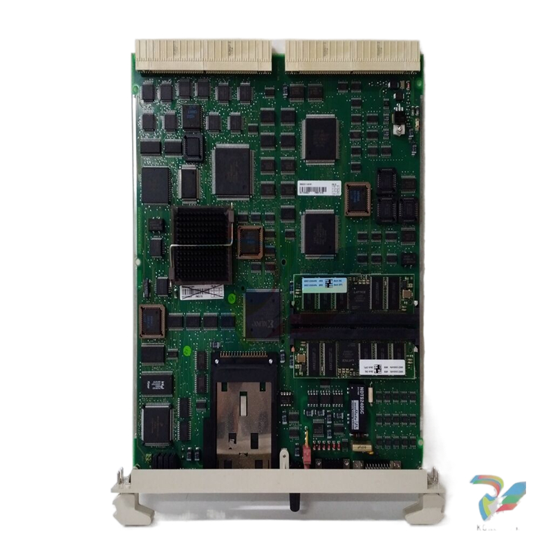
Overview The NTAC-01 is compatible with ACS 600 drives with Standard
Application Program versions from 2.8 to 3.0. Version 5.0 (and later)
require the use of the NTAC-02. Thus, NTAC-01 and NTAC-02 are not
interchangeable.
Differences between
NTAC-01 and NTAC-02
All information about the NTAC-02 given elsewhere in this manual also
applies to the NTAC-01, with the exception of what is listed in this
section.
Terminal Designations The terminals of the NTAC-01 can be connected as shown for the
NTAC-02 in Chapter 3. Although unmarked on the label, NTAC-01
terminal X2:1 can actually be used as an additional -V terminal.
Moreover, the SH and PE terminals are both connected to module
earth.
Encoder Supply Voltage The encoder supply voltages available from the NTAC-01 are 12 and
24 V (instead of 15 and 24 V available with the NTAC-02).
Cabling The maximum encoder cable length for the NTAC-01 is 150 m.
Technical Data Encoder inputs:
• Logical thresholds (12 V encoder supply): “1” > 8.3 V, “0” < 3.7 V
NTAC Setup in Std.
Application Program
V2.8 to 3.0
This section only applies when an NTAC-01 module is connected to an
ACS 600 equipped with Standard Application Program version 2.8 to
3.0. Users of other application programs should refer to the drive
manuals.
Before adjusting the parameters, ensure that the module node number
is set to 16. Note that the setting takes effect only on the following
module power-up.
98.1 ENCODER
MODULE
This parameter activates the communication between the ACS 600 and
the NTAC module.
YES
Communication is active.
NO
Communication is not active.
- YOKOGAWA
- Reliance
- ADVANCED
- SEW
- ProSoft
- WATLOW
- Kongsberg
- FANUC
- VSD
- DCS
- PLC
- man-machine
- Covid-19
- Energy and Gender
- Energy Access
- Renewable Integration
- Energy Subsidies
- Energy and Water
- Net zero emission
- Energy Security
- Critical Minerals
- A-B
- petroleum
- Mine scale
- Sewage treatment
- cement
- architecture
- Industrial information
- New energy
- Automobile market
- electricity
- Construction site
- HIMA
- ABB
- Rockwell
- Schneider Modicon
- Siemens
- xYCOM
- Yaskawa
- Woodward
- BOSCH Rexroth
- MOOG
- General Electric
- American NI
- Rolls-Royce
- CTI
- Honeywell
- EMERSON
- MAN
- GE
- TRICONEX
- Control Wave
- ALSTOM
- AMAT
- STUDER
- KONGSBERG
- MOTOROLA
- DANAHER MOTION
- Bentley
- Galil
- EATON
- MOLEX
- Triconex
- DEIF
- B&W
- ZYGO
- Aerotech
- DANFOSS
- KOLLMORGEN
- Beijer
- Endress+Hauser
- schneider
- Foxboro
- KB
- REXROTH
- YAMAHA
- Johnson
- Westinghouse
- WAGO
- TOSHIBA
- TEKTRONIX
- BENDER
- BMCM
- SMC
- HITACHI
- HIRSCHMANN
- XP POWER
- Baldor
- Meggitt
- SHINKAWA
- Other Brands
- UniOP
- KUKA
- IBA
- Beckhoff
- ADLINK
51
-
Beckhoff CX1100-0910 - Power Supply Module
-
Beckhoff C5210-0010 - Communication Module C5210
-
BECKHOFF KL1352 - Bus Terminal SET OF 2 FREE FAST SHIP
-
Beckhoff EL3058 - 8 x analog input single ended 4...20mA 85惟 shunt 12bit
-
Beckoff CX1100-0920 - UPS Module 24VDC (US SELLER) * *
-
BECKHOFF C6920-0000 - C69200000 PLC Moudule
-
Beckhoff CX5120-0115 - CPU controller module CX5120-0115
-
Unknown 15F5C1E-Y50A - Of Frequency Converters
-
Beckhoff AX5118-0000-0200 - Servo Drive HTP0
-
BECKHOFF AX5106-0000-0200 - Servo Drive
-
Beckhoff CX5240-0175 - Module (free) #U2327D YG
-
Beckhoff CP6607-0001-0000 - Compact PC Panel Economy Installation Operator 5,7 "
-
Beckhoff EP3744-0041 - 2022 EP37440041 Module
-
Beckhoff CP6209-0001-0020 - 6.5" PC Touch Screen Control Panel 24VDC
-
Beckhoff CX9020-0111 - /U900 +8x+2xEL3121+1x EL9410+3xEL1008+1x EL2008 Set
-
Beckhoff C6525-1030-0050 - Industrial PC
-
Beckoff CX1100-0920 - UPS Module 24VDC (US SELLER)
-
Beckhoff CX5010-0120 - CX5010 Processor Intel Atom Z510 B24
-
Siemens 6FC5203-0AF04-1BA1 - Operation Panel
-
Beckhoff CX5230-0175 - / 000029724 Embedded PC / Industrial PC on Rail
-
Beckhoff CP3916-0000 - industrielles Anzeige- und Bedienterminal
-
BECKHOFF CX1500-M310 - CX1000-N000 CX1000-0011 CX1000-C00L CX1100-0002 PLC Module
-
Beckhoff EL1872 - 16-channel digital input terminal
-
BECKHOFF EP2318-0001 - module
-
Beckhoff CX9020-0110 - Basic CPU Module
-
Beckhoff EL2564 - EtherCAT Terminal, 4-channel LED output, 5鈥?8VDC, 4A, RGBW
-
Beckhoff CX5130-0155 - /000105637 Automation Embedded PC
-
B&R 400 - Power Control Panel Rev D0 24 VDC
-
Beckhoff CX2020-0155 - module
-
Beckhoff CX9020-0115 - PLC Module
-
BECKHOFF EL6695 - PLC EL 6695
-
BECKHOFF EL7047 - PLC Modules
-
Beckhoff CX1000-0012 - Control HW 2.2 + CX1500-M310 + CX1000-C00L + CX1100-0002+
-
Beckhoff C6920-1039-0030 - control cabinet industrial PC CPU Celeron 1.90 GHz, 2 cores
-
BECKHOFF CX1100-0910 - PLC Module#
-
Beckhoff IL2301-B318-0000 - Coupler Box 4 Channel Digital Input |
-
Beckhoff CX7080 - Module
-
Beckhoff C6930-0060 - Industrial PC
-
Beckhoff CP7902-1060-0000 - Touchscreen 15 " CP7902
-
beckhoff CX9020-0111 - Controller module or UPS
-
Beckhoff CX8091 - PLC Module CX8091
-
Beckhoff C6640-1008-0030 - Control Cabinet Industrial PC
-
BECKHOFF CX1100-0920 - module
-
Beckhoff C9900-M921 - see pictures
-
BECKHOFF CP6829-0001-0000 - Touch Panel
-
BECKHOFF C6930-0060 - Industrial Computer
-
BECKHOFF CX8050 - PLC module
-
Beckhoff CP6202-0021-0020 - Touch Screen #
-
BECKHOFF AM3031-0C20-0000 - SERVO MOTOR
-
Unknown BCH1302N11A1C - Servo motor
-
Beckhoff EL2502 - 2-channel pulse width output terminal
-
Beckhoff EL6731 - Profibus Master / *Rev: 0025
-
Beckhoff CP3918-0010 - Control Panel
-
BECKHOFF CP2915-0010 - [24 MONTH WARRANTY] Control Panel
-
Beckhoff AX5203-0000-0202 - Servo Drive
-
Schneider TSXDSY64T2K - PLC OUTPUT MODULE
-
Beckhoff EP4174-0002 - Module-
-
Beckhoff IL2302-B318-0000 - Profibus Box
-
Beckhoff CP6709-0001-0000 - Touchpanel
-
BECKHOFF CX2030-0123 - Controller
-
Beckhoff CX9020-0111 - Processor Module
-
Beckhoff CX1020-0000 - CX Basic CPU Module
-
Beckhoff AX2003-AS - Servo Drive HTP0
-
Beckhoff C6240-1052-0040 - 4-086-06-3073 Industrial Computer CB1052-0003
-
Beckhoff EL1918 - 8 xTwinSAFE Input
-
Beckhoff AM8072-0R20-0000 - Servomotor
-
BECKHOFF AM8021-1B21-0000 - servo motor #T882 YS
-
Beckhoff EL6224 - 4 X Terminal IO-LINK
-
Beckhoff CX5140-0135 - embedded PC with Intel Atom processor 4 GB HW 3.6
-
Beckhoff CP7201-1000-0000 - Panel PC #
-
Beckhoff CX5130-0121 - Embedded-PC 4GB CPU Module HW 2.5 Industrial PC
-
Beckhoff AM8022-0D41-1002 - Servomotor
-
BECKHOFF CX2030-0130 - Module
-
BECKHOFF EL1872 - 16-channel digital input terminal
-
Unknown GXMMW.A203P33 - 1pc encoder
-
Beckhoff EL6631-0000 - EtherCAT Terminal 2-Port EL 6631
-
BECKHOFF C6925-0030 - Industrial Computer
-
Beckhoff CX8190 - A Module
-
BECKHOFF CX2040-0135 - CX2040-0135/000000927 CPU BASE MODULE i7 2715QE 2.1GHz --
-
BECKHOFF KL6023-0000 - Wireless adapter
-
Saia Burgess PCD7.F700 - PCD7F700 Communication Module
-
Beckhoff CX5130-0112 - CPU Module
-
BECKHOFF CX1020-N010 - CX1020-N000 CX1020-0111 CX1100-0004 EL2008 EL3064 EL4004
-
Beckhoff EP1819-0021 - A Module
-
Beckhoff CX2030-0120 - / 4gb with CX2100 0004
-
B&R X20-XC-0292 - Automation Powerlink Ethernet Bus Controller Module
-
Beckhoff BK3110 - One PLC Module
-
BECKHOFF KL3222 - PLC Module
-
BECKHOFF CX1500-M310 - CX1000-N000 CX1000-0011 CX1000-C00L CX1100-0002 PLC MODULE
-
Beckhoff CP3918-0010 - Control Panel
-
Beckhoff CX2030-0100-1002 - /4GB + CX2100 + CX2550 + CX2500-0060 + SSD
-
Beckhoff EP1816-0008 - PLC Module
-
Beckhoff CX5130-0112 - Module
-
Beckhoff Cx1500-m750 - CPU Hw: 1.4
-
BECKHOFF AX5112-0000-0200 - AX511200000200 Servo Driver
-
Beckhoff EL3751 - EtherCAT Terminal 1 Channel Analog Input Multifunction 24 Bit
-
Beckhoff CX1100-0002 - Power Supply Module
-
Beckhoff CP3916-1016-0010 - Control Panel
-
BECKHOFF CX9001-1101 - #NAME?
-
Beckhoff EP3174-0002 - EtherCAT Box Module
-
Beckhoff C6030-0070 - servo drive
-
Beckhoff CX2020-0120 - /4GB CPU, CX2100-0904, 3x EL6900, EL1904, 16GB Memory
-
BECKHOFF C6110 - BOX-PC 113608
-
BECKHOFF EK1914 - module #P
-
Beckhoff C6140 - Ipox IP-4GVI63 + CH7009A_DVI_TV + SIEMENS A5E00369843 + WD800AAJB
-
Beckhoff CX5020-0111 - controller Good quality
-
BECKHOFF C6015-0010 - / 6559380 ULTRA-COMPACT INDUSTRIAL PC ()
-
Beckhoff AX5203-0000-0200 - PLC module
-
Beckhoff EL2872 - 16-channel digital output terminal
-
BECKHOFF C3640-0000 - Panel Industrial PC 100/240VAC 128MB E0122L
-
Beckhoff CX8031 - Module
-
Beckhoff CX5020-0120-1002 - PLC module#
-
Beckhoff C6140 - M845B + SIEMENS A5E00369843 + C9900_A159_1 + AUTOMATA CAN PCI 1N
-
BECKHOFF AX5112-0000-0200 - Servo Drive*ie
-
B&R ECPA42-01 - Analog Output Module 4-Channel, +/- 10V Output Signal, 20mA Max
-
Beckhoff EL6631-0010 - PLC Module
-
BECKHOFF C6930-0070 - CONTROL CABINET INDUSTRIAL PC
-
BECKHOFF AX5112-0000-0200 - AX511200000200 Servo Driver
-
BECKHOFF EK9000 - Programmable Logic Controller Module EK9000 EK9000
-
BECKHOFF C6920-1028-0000 - Industrial computer
-
Beckhoff CX2030-0120 - controller Module
-
Beckhoff BX8000-0000 - Bus Terminal Controller HW 4.4
-
B&R 3NC154.60-2 - Positioning Module#
-
BECKHOFF CX1020-0122 - PLC module
-
Beckhoff AM3032-0D40-0000 - Servo Motor
-
BECKHOFF CX5020-0111 - CPU Module CX5020-0111
-
Beckhoff CB1051 - G5 Motherboard
-
BECKHOFF KL2641 - 1-channel relay output terminal

K-JIANG

Add: Jimei North Road, Jimei District, Xiamen, Fujian, China
Tell:+86-15305925923