
K-WANG


TOSHIBA TOSBERT TM VF-nC1 Industrial Inverter
Applicable motor: only for three-phase induction motors, cannot drive single-phase motors
Power and voltage specifications: covering three voltage levels, with specific parameters as shown in the table below:
Voltage level, power range (kW), model example, output current (A), suitable motor capacity (kW)
Single phase 100V level 0.1-0.75 VFNC1S-1001P 0.7-4.0 0.1-0.75
Single phase 200V level 0.2-2.2 VFNC1S-2002P 1.4-10.0 0.2-2.2
Three phase 200V level 0.1-2.2 VFNC1-2001P 0.7-10.0 0.1-2.2
Single phase 200V level (with filter) 0.2-2.2 VFNC1S-2002PL 1.2-10.7 0.2-2.2
Core control method: Adopting sine wave PWM control, the output frequency range is 0.5-200Hz (default 0.5-80Hz), and the voltage/frequency characteristics can be adjusted through parameters (V/f constant, sensorless vector control).
TOSHIBA TOSBERT TM VF-nC1 Industrial Inverter
Product Overview
1.1 Basic Information
Model: TOSBERT TM VF-nC1 Industrial Inverter
Applicable motor: only for three-phase induction motors, cannot drive single-phase motors
Power and voltage specifications: covering three voltage levels, with specific parameters as shown in the table below:
Voltage level, power range (kW), model example, output current (A), suitable motor capacity (kW)
Single phase 100V level 0.1-0.75 VFNC1S-1001P 0.7-4.0 0.1-0.75
Single phase 200V level 0.2-2.2 VFNC1S-2002P 1.4-10.0 0.2-2.2
Three phase 200V level 0.1-2.2 VFNC1-2001P 0.7-10.0 0.1-2.2
Single phase 200V level (with filter) 0.2-2.2 VFNC1S-2002PL 1.2-10.7 0.2-2.2
Core control method: Adopting sine wave PWM control, the output frequency range is 0.5-200Hz (default 0.5-80Hz), and the voltage/frequency characteristics can be adjusted through parameters (V/f constant, sensorless vector control).
Safety regulations
2.1 Warning System
The manual divides safety warnings into two levels, clarifying the consequences of risks and operational requirements:
Typical scenario examples of warning type meanings
Warning: Incorrect operation may result in death or serious injury. Disassembling the front cover while live, connecting input power to output terminals, and operating without grounding
Incorrect handling of the solution may result in minor injuries or property damage. Touching the heat sink, using incompatible chemicals, and installing in a vibrating environment
2.2 Mandatory Safety Requirements
Grounding: D-type grounding (formerly Class 3 grounding) must be used, and the grounding wire diameter should be ≥ 3.5mm ² (refer to the terminal specification table for details) to ensure safe conduction of leakage current in case of fault.
Power off waiting: After disconnecting the input power, wait for at least 15 minutes to confirm that the charge light is off and the DC main circuit voltage is ≤ 45V before touching the terminal.
Installation base: It needs to be fixed on a metal base that can withstand the weight of the equipment to prevent it from falling; Choose NEMA 3R protection model (such as 5000 series) for outdoor/harsh environments.
Emergency stop: It must be equipped with an emergency stop device independent of the frequency converter (such as mechanical braking), and the frequency converter alone cannot achieve immediate shutdown.
Parameter settings
3.1 Parameter Classification and Core Parameters
Parameters are divided into three categories: basic parameters, extended parameters, and special parameters. The core parameters and functions are as follows:
Parameter Category Parameter Code Function Description Adjustment Range Default Values Key Role
Basic parameter CMod instruction mode selection (source of run/stop instructions) 0- Terminal board/1- Panel 1 Determine control mode
FMod frequency setting mode selection: 0- Terminal board/1- Panel, etc. 2. Determine the frequency adjustment method
ACC/DEC acceleration time 1/deceleration time 1 0.1-3000 seconds 10.0s to prevent current overload during startup/shutdown
FH/UL maximum frequency/upper limit frequency 30-200Hz/0.5-FH 80Hz/80Hz limits the maximum operating frequency of the motor
Extended parameter F300 PWM carrier frequency 2/4/8/12/16kHz 12kHz balanced motor noise and inverter losses
F250-252 DC braking parameters (starting frequency/current/time) 0.0-FHHz/0-100/0-20s 0.0Hz/50%/1.0s to achieve rapid shutdown
OLn electronic thermal protection characteristics 0-7 (corresponding to different protections) 0 adaptation standard motor/VF motor protection
Special parameter RUL wizard function (quick setting) 0-5 (5-class wizard) 0 Simplified parameter configuration (such as basic settings)
RUH History Record Function - Display the Last 5 Modified Parameters
3.2 Parameter Setting Process
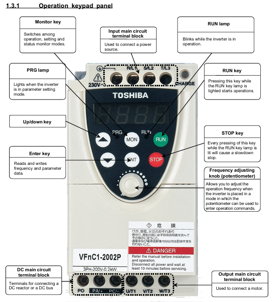
Enter setting mode: Press the MON key to switch to "parameter setting mode" (display "RUH");
Parameter selection: Use the △/▽ keys to select the target parameter (such as CMod);
Modify parameters: Press the ENT key to enter editing, and then use the △/▽ keys to adjust the values;
Save parameters: Press the ENT key again, and the parameters and values will alternate to indicate successful saving;
Reset default: Set the basic parameter "Eyp" to 3 to restore all parameters to their factory default values (with the need to shut down first).
Installation and wiring
4.1 Installation environment requirements
Temperature: Operating environment temperature * * -10 ℃ -50 ℃ * *. When the ambient temperature is greater than 40 ℃, the warning label on the top of the equipment should be removed and the rated output current should be reduced (such as the current of the 2007P model dropping from 4A to 3.6A at 40-50 ℃);
Humidity: Relative humidity of 20% -93%, no condensation;
Vibration: Vibration acceleration<5.9m/s ² (10-55Hz), avoid installing near strong vibration equipment such as machine tools;
Other: No dust, corrosive gases, oil mist, keep away from heat sources (such as transformers, heaters).
4.2 Terminal Wiring Specification
Main circuit terminals:
Screw specifications: M3 (low power)/M3.5 (high power), tightening torque of 0.8N · m/1.0N · m respectively;
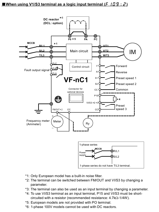
Wiring requirements: Connect the input (R/L1, S/L2, T/L3) to the power supply, and the output (U/T1, V/T2, W/T3) to the motor. Reverse connection is prohibited as it may damage the inverter;
Grounding terminal: It needs to be independently grounded with a wire diameter of ≥ 3.5mm ² (refer to section 10.1 wiring table).
Control circuit terminals:
Screw specifications: M2/M3, wire diameter 0.3-1.5mm ², sheath stripping length 5-6mm;
Wiring taboos: Control circuit and main circuit wiring should be separated (not parallel, not bundled, different conduit) to avoid interference.
4.3 Wiring precautions
It is prohibited to connect capacitive devices (such as noise filters and surge absorbers) on the output side, as this may cause a fire;
The length of the main circuit line is ≤ 30m, and if it exceeds this limit, the wire diameter needs to be increased (for example, for a 200V level 0.75kW motor, a wire length>30m requires a wire of ≥ 2.5mm ²);
When multiple inverters share a power supply, each one needs to be equipped with an independent MCCB (circuit breaker) to avoid the spread of faults.
Operation and monitoring
5.1 Operating Mode
Panel control: Set CMod=1, start with RUN key, stop with STOP key, adjust frequency with △/▽ key;
Terminal control: Set CMod to 0 and control operation by short circuiting the F-CC (forward rotation) and R-CC (reverse rotation) terminals;
Jog operation (JOG): Set the input terminal function to "JOG", the motor runs at a fixed frequency of 5Hz when short circuited, and stops freely after disconnection;
Preset speed operation: By allocating SS1-SS4 terminals (a total of 4 terminals), 15 levels of preset speed can be achieved (F287-F294 parameters need to be set).
5.2 Status Monitoring
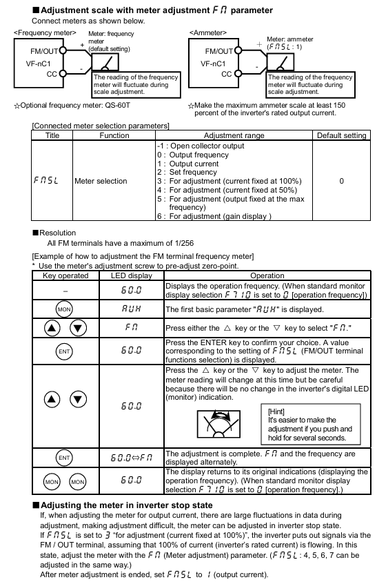
Monitoring content: The output frequency, load current (%/A), input voltage (DC), output voltage (%/V), cumulative running time (0.01=1 hour), etc. can be viewed through the "status monitoring mode" (press MON button twice);
Fault display: When tripped, the LED displays a fault code (such as "OC1" indicating acceleration overcurrent), and the FL relay operates (fault output);
Alarm message: Non trip warning (such as "rEr" indicating retry), only prompts not to stop the machine, and attention should be paid to the equipment status.
Fault handling
6.1 Common tripping faults and remedies
Fault code, fault type, possible cause, remedial measures
OC1 acceleration overcurrent acceleration time is too short, motor impedance is too small, extending ACC time (such as changing from 10s to 20s), checking motor insulation
OP2 deceleration overvoltage deceleration time too short, excessive regenerative energy prolongs dEC time, F305 is enabled (overvoltage limited operation)
OH inverter overheating fan fault, poor ventilation, environment overheating. Replace the fan, clean the ventilation opening, and improve environmental heat dissipation
OL2 motor overload, excessive load, long low-speed operation time to reduce load, adjust electronic thermal protection level (OLn=4 compatible with VF motor)
6.2 Fault reset method
Panel reset: In the shutdown state, press the STOP button to display "LLr", then press the STOP button to reset (the fault needs to be eliminated first);
External reset: Short circuit the control terminal RST to CC and disconnect it (RST function needs to be assigned first);
Power off reset: Disconnect the input power supply, wait for 15 minutes, and then power it back on (used in emergency situations, not recommended for frequent operation).
Maintenance and Quality Assurance
7.1 Regular Maintenance Plan
Maintenance Type Cycle Maintenance Content Precautions
Daily inspection of environmental temperature, vibration and noise, load current, and alarm light status without stopping the machine. Visual and instrument checks are required
During the 3-6 month maintenance cycle, terminal tightening, dust removal (ventilation/circuit board), and capacitor inspection must be carried out by cutting off the power for 15 minutes and confirming that the voltage is ≤ 45V before operation
Long term storage: Power on for more than 5 hours every 2 years (motor disconnected), gradually increase the voltage with a transformer to restore capacitor performance, and avoid direct commercial power supply
7.2 Service life and replacement of vulnerable parts
Cooling fan: With a lifespan of approximately 30000 hours (2-3 years of continuous operation), it should be replaced in case of abnormal noise or stoppage;
Electrolytic capacitor: The lifespan of the smoothing capacitor in the main circuit is about 5 years (normal environment). Check for no leakage and ensure that the safety valve is not protruding. Otherwise, replace it;
Fuse: with a lifespan of about 10 years, regularly inspect the appearance, and replace it with the same specification (such as CC/J grade 8A) after melting.
7.3 Warranty Scope
Warranty period: 12 months from the delivery date, only covering the frequency converter host;
Free repair: Parts malfunctions that occur under normal use (such as fans and capacitors);
Disclaimer:
Improper use (such as overload, misconnected power supply);
Self modification/repair;
Natural disasters (fire, earthquake) or abnormal voltage;
Out of range applications (such as driving single-phase motors).
Compliance and Disposal
8.1 Certification Compliance Requirements
CE certification:
EMI filters need to be installed on the input side (such as EMFA2006Z suitable for 200V low power);
Shielded wires are used for the main circuit/control circuit, and the shielding layer is grounded (with a distance of less than 10cm from the inverter);
UL/CSA certification:
Use copper wires above 75 ℃, equipped with CC/J level fuses (such as 4A fuses for the 2002P model);
Branch circuit protection must comply with local electrical regulations (such as NEC in the United States and CEC in Canada).
8.2 Equipment disposal
Mandatory requirement: Waste frequency converters must be disposed of by professional industrial waste disposal institutions (self disassembly is prohibited);
Risk Warning: Self disposal may lead to capacitor explosion and release of toxic gases, violating the Waste Disposal and Cleaning Law;
Contact organization: You can contact Toshiba's regional branches at the end of the manual to obtain compliance disposal channels.
- YOKOGAWA
- Reliance
- ADVANCED
- SEW
- ProSoft
- WATLOW
- Kongsberg
- FANUC
- VSD
- DCS
- PLC
- man-machine
- Covid-19
- Energy and Gender
- Energy Access
- Renewable Integration
- Energy Subsidies
- Energy and Water
- Net zero emission
- Energy Security
- Critical Minerals
- A-B
- petroleum
- Mine scale
- Sewage treatment
- cement
- architecture
- Industrial information
- New energy
- Automobile market
- electricity
- Construction site
- HIMA
- ABB
- Rockwell
- Schneider Modicon
- Siemens
- xYCOM
- Yaskawa
- Woodward
- BOSCH Rexroth
- MOOG
- General Electric
- American NI
- Rolls-Royce
- CTI
- Honeywell
- EMERSON
- MAN
- GE
- TRICONEX
- Control Wave
- ALSTOM
- AMAT
- STUDER
- KONGSBERG
- MOTOROLA
- DANAHER MOTION
- Bentley
- Galil
- EATON
- MOLEX
- Triconex
- DEIF
- B&W
- ZYGO
- Aerotech
- DANFOSS
- KOLLMORGEN
- Beijer
- Endress+Hauser
- schneider
- Foxboro
- KB
- REXROTH
- YAMAHA
- Johnson
- Westinghouse
- WAGO
- TOSHIBA
- TEKTRONIX
- BENDER
- BMCM
- SMC
- HITACHI
- HIRSCHMANN
- XP POWER
- Baldor
- Meggitt
- SHINKAWA
- Other Brands
- UniOP
- KUKA
- IBA
- Beckhoff
-
ADLINK CPCI-6860A - 51-31310-OB10 industrial motherboard CompactPCI SBC
-
ADLINK AmITX-SL-G-H110 - 51-7A104-0A30 Mini-ITX Industrial Motherboard
-
ADLINK PXI-2005-003 - CPCI Industrial PC Data Acquisition Card Multi-Function DAQ
-
ADLINK DININ-814M - 51-14032-0A3D SCSI-100P cable connection Interface Terminal Board
-
ADLINK CPCI-3920NA/C2D15/M1G - 3U CompactPCI Intel Core 2 Duo Single Board Computer
-
ADLINK PCIE-8560 - 51-18014-0A20 Communication Card High Speed DAQ
-
ADLINK PCI-C154+ - Motion Control Card 4-axis Motion Controller Board
-
ADLINK PCI-RTV24 - image capture card Analog Video Frame Grabber
-
ADLINK NuPRO-842LV/P - 51-41360-0B30 Industrial Motherboard CPU Board
-
ADLINK cBP-3208/3208R - CPCI Board 3U 8-Slot CompactPCI Backplane
-
ADLINK PCI-8164 - 4-Axis Motion Controller PCI Card 51-12406-0A40
-
ADLINK PCIe-GIE64+ - 4-CH GigE Vision PoE+ Frame Grabber Video Capture Card
-
ADLINK CPCI-6860 / 6860A - CompactPCI Dual Xeon Single Board Computer
-
ADLINK IEC-915GV - REV 1.1 Industrial motherboard CPU Board
-
ADLINK ND-6520 - Technology RS-232 to RS-422RS-485 Converter NuDAM Module
-
ADLINK RTV-24 / PCI-MP4S - 51-12519-1C30 4-Channel Real Time Video Capture Board
-
ADLINK cPCI-6910 / cPCI-6910AM/M1G - cPCI-6910AM/DXL16/M1G/S80G(G)-3120 BOARD CompactPCI SBC
-
ADLINK NUPRO-A40H - Linghua 51-41807-1A30 Industrial Control Computer Motherboard
-
ADLINK USB-3488A - USB to GPIB INTERFACE USB-3488A(G) Controller Module
-
ADLINK PCI-8134A - motion control card 4-Axis Controller Card
-
ADLINK PCI-7432 - Board 32-Channel input / 32-output Isolated Digital I/O PCI Card
-
ADLINK PCI-8134A - 51-12421-0A10 motion controller card tested
-
ADLINK LPCIe-7230 - 32 CH Isolated Input/output Card 2 Interrupts Low Profile PCIe
-
ADLINK NuPRO-E340 - industrial computer motherboard 51-47807-0A30 PICMG 1.3 SHB
-
ADLINK PCI-7434 - High-speed Digital Acquisition Card 64-CH Isolated DO Card
-
ADLINK NuPRO-E330 - 51-41805-0A20 Indsutrial Board SHB Single Board Computer
-
ADLINK PCI-7248 - OPTO-22 48 CHANNEL DIO DIGITAL TTL/DTL I/O 51-12006-0A40 GP
-
ADLINK PCI-8134 - Motion control card 4-Axis Controller Card
-
ADLINK AMP-208C - Movimiento Control Tarjeta 51-12420-1A20 W/Expansión & Breakout
-
ADLINK PCI-8164 - 51-12406-0A40 PCB Board 4-Axis Motion Controller Card
-
ADLINK DIN-68Y-SGII / DIN-68M-J3A - Terminal Board Connector Interface Block
-
ADLINK PCIe-7432 - Technology 51-18402-0A10 PCIe Card With High Input Range
-
ADLINK PCI-8144 / PCI-8144N - Motion control card 4-Axis Stepper Controller Card
-
ADLINK HSL-HUB3/REPEATER - HIGH SPEED LINK EXTENSION MODULES Distributed Hub Module
-
ADLINK ND-6017 - Data Logging + Acquisition 8CH A/D input Mod NuDAM Module
-
ADLINK LPCIe-7250 - data acquisition card Low Profile 8-CH Relay Output Card
-
ADLINK PCI-7432 - I/O card 64-CH Isolated Digital Input Output PCI Card
-
ADLINK IMB-M43H - industrial control computer motherboard Q87 Chip Micro-ATX
-
ADLINK MP-C154 - Motion control Card 4-Axis Motion Controller Board
-
ADLINK PCI-RTV24 - image capture card Video Frame Grabber Card
-
ADLINK PCI-7250 - 8-CH Relay Output & 8-CH Isolated DI Card
-
ADLINK PCI-6308V - 8-CH 12-Bit Isolated Analog Output PCI Card PCB-I-E-1148=6EX2
-
ADLINK PCI-7248 - capture card 48-CH Opto-22 Compatible DIO Card
-
ADLINK HSL-AI16A02-M-VV - Analog Input Output Distributed Module
-
ADLINK NuPRO-A301 - Rev:1.4 NUPRO-A301 PICMG Full-Size Single Board Computer
-
ADLINK PCI-6208V-GL - 8-CH Voltage Analog Output PCI Card
-
ADLINK PCI-8134A - 51-12421-0A10 4-Axis Motion Controller Card
-
ADLINK MNET-S23 - TECHNOLOGY MNET S23 - SERVO DRIVER CONTROL MODULE
-
ADLINK M-342 - ATX I3 I5 I7 Q67 Industrial Motherboard
-
ADLINK NUPRO-780 - Industrial Motherboard CPU Board PICMG SBC
-
ADLINK MP-C154 / MP-C152 - 4-Axis Motion Control Card Pulse-Train Controller
-
ADLINK NuPRO-935A/LV10B0 - Motherboard 51-41802-0A10 GP w/RAM Industrial Control Board
-
ADLINK MP-C154 - Motion control card 4-Axis Motion Controller Mainboard
-
ADLINK PCI-7250 - PCI Acquisition Card 8-CH Relay Output Isolated DI Card
-
ADLINK ACL-7124 - Technology Inc.24 DIO Card Digital Input Output Card
-
ADLINK PCI-8554 A2 - Timer/Counter Data Acquisition Card
-
ADLINK DIN-825-GP4 - Terminal Block Interface Board Breakout Module
-
ADLINK NuPR0-761 - REV:1.1 Industrial motherboard Full-Size PICMG SBC
-
ADLINK MXE-1401/M8G (G) - Matrix Fanless Embedded Computer Industrial PC
-
ADLINK HSL-DI16DO16-UD-NN - Digital 16 Channel I/O Mod Distributed I/O Module
-
ADLINK ND6520 - NUDAM INTELLIGENT DA&C MODULE RS232-RS-422/RS485 CONVERTOR
-
ADLINK NUPRO-761 - REV:1.1 Industrial Motherboard CPU Board
-
ADLINK AMP-208C - Motion Control Card 51-12420-1A20 DSP-based 8-axis
-
ADLINK NuPRO-A301REV 1.4 - with packaging industrial computer motherboard PICMG SBC
-
ADLINK PCM-9112+ - 51-12300-0A2 industrial motherboard Multi-Function DAQ PC/104 Module
-
ADLINK PCM-7250+ - 8-CH Relay Outputs & 8-CH Isolated DI Module PC/104
-
ADLINK PCI-RTV24 - Image capture card Analog Video Frame Grabber
-
ADLINK PCI-8134 - Motion Controller PCI Card 4-Axis Controller Board
-
ADLINK PCI-7432 - Isolated Digital I/O PCI Card
-
ADLINK PCI-8554 A2 - acquisition card Timer/Counter Card
-
ADLINK PCI-8132 - Rev.A2 2-Axis Servo & Stepper Motion Controller Card
-
ADLINK PCI-8132 - Data Acquisition card 2-Axis Motion Controller Card
-
ADLINK EBP-13E4 - 51-46703-0A30 Industrial Backplane Board Passive Backplane
-
ADLINK PCI-800L - Electronic Card Interface Controller Card
-
ADLINK PCIe-GIE72 - 51-18531-0A10 PCB Board GigE Vision Frame Grabber
-
ADLINK DAQ-2010(G)-OOBO - Simultaneous-Sampling Multi-Function DAQ Card
-
ADLINK PCI-9112 - REV.B1 Multifunction DAQ Card Data Acquisition Card
-
ADLINK PCI-7230 - 51-12003-DA60 32-CH Isolated Digital I/O Card
-
ADLINK PCI-7432 - Data Acquisition Card Isolated Digital I/O PCI Card
-
ADLINK ETX-AT-N270-18/LXE - 51-71111-0A20 ETX CPU Module Motherboard
-
ADLINK HSL-DI32-UD-N - DIGITAL INPUT 32 POINTS MODULE Distributed I/O
-
ADLINK AMP-204C - Motion Control card DSP-Based 4-Axis Advanced Controller
-
ADLINK MNET-4XMOG-0050 - Four-axis Motion Controller Distributed Motion Module
-
ADLINK AMP-204C - Motion control card DSP-Based 4-Axis Pulse-Train Controller
-
ADLINK PCI-7442 - Switch card 64-Channel Datalogging & Acquisition Card
-
ADLINK M-302 - Industrial control motherboard ATX PC Board
-
ADLINK NUPRO-852 / NUPRO-852LV - Industrial motherboard Single Board Computer
-
ADLINK PCI-8134 - REV.B1. 4-Axis Motion Controller Card
-
ADLINK PCI-GIE62 + - 51-18502-0A20 2-CH GigE Vision Frame Grabber PoE Card
-
ADLINK PCI-MPG24 - 51-12523-0B20 MPEG4 Card Video Compression Hardware
-
ADLINK HSL-TB32-M-DIN - 32-CH I/O TERMINAL W/ HSL-AI16AO2-M-VV MODULE
-
ADLINK PCI-M114-GL - PCB Ver 2.1 Motion Controller Axis Card
-
ADLINK IMB-M40H - SYM76996H61 motherboard Industrial Computer Mainboard
-
ADLINK NUPRO-A40H - 51-41807-1A20 industrial control motherboard H61 Chip
-
ADLINK PCI-M114-GL - Axis Card Data Acquisition Card PCB VER2.2 Motion Controller
-
ADLINK PCI-8134 - Motion Controller PCI Card 4-Axis Controller Board
-
ADLINK PCI-8102 - Motion control card 2-Axis Servo & Stepper Controller
-
ADLINK NuPRO-841REV:3.0 - motherboard Industrial Control PC Board
-
ADLINK HSL-TB32-U-DIN REV A1 - Breakout Terminal Board Field I/O Module
-
ADLINK AMP-204C - Motion Control card DSP-Based 4-Axis Pulse-Train Controller
-
ADLINK NUPRO-A40H - 51-41807-1A20 industrial control motherboard H61 PC Board
-
ADLINK PCI-6308A / PCI-6308V - 51-12202-0A50 Isolated Analog Output Card
-
ADLINK AMP-204C - DSP-Based 4-Axis Advanced Pulse-Train Motion Controller
-
ADLINK PCI-7434 - Technology 64-Channel Isolated Digital I/O PCI Cards
-
ADLINK CPCI-6840 / CPCI-6840V / PM16/M1G-12G0 - CompactPCI Single Board Computer CPU Module
-
ADLINK PCIE-GIE74 - Motherboard Video Capture Card 51-18531-0A10 Frame Grabber
-
ADLINK NuPRO-E330 - industrial computer equipment motherboard Control Mainboard
-
ADLINK AMP-208C / 51-12420-1A20 - Motion Control Card W/ Expansion & Breakout Board
-
ADLINK HPCI-14S12U - industrial computer baseboard Passive Backplane 14 Slots
-
ADLINK PCI-8164 - 4-Axis Motion Controller PCI Card W/ 1x Cable, 1x Breakout Box
-
ADLINK PCIe-RTV24 - 51-18016-0A20 Image Acquisition Video Capture Card
-
ADLINK M-342 - 5 PCI ATX Motherboard Industrial PC Mainboard
-
ADLINK PCI-FIW64 - 4/2 Channel IEEE1394B Image Capture Card FireWire Frame Grabber
-
ADLINK PCI-7432 - digital IO card 64-CH Isolated Digital Input Output Card
-
ADLINK 51-12001-0C20 - Circuit Board PCI-7200 Data Acquisition Controller Card
-
ADLINK PXI-3920 - PXI 3U cPCI Industrial Controller Embedded System CPU Board
-
ADLINK NuPRO-841REV:2.0 - motherboard Industrial Control PC Board
-
ADLINK NuPro-E330 - 51-41805-0A20 PCB Industrial Control Computer Motherboard
-
ADLINK PCI-RTV24 - Image capture card Analog Video Frame Grabber
-
ADLINK PCI-7442 - Switch card 64-Channel Datalogging & Acquisition Card
-
ADLINK HPX-13S4 - device baseboard Passive Backplane Riser Card
-
ADLINK PCI-9112 REV A.1 - Multi Function DA&C Board Data Acquisition Card
-
ADLINK PCI-7248 - 51-12006-0A40 Card Control 48-CH Digital I/O Module
-
ADLINK CPCI-6860 / 6860A - motherboard CompactPCI Dual Xeon Single Board Computer
-
ADLINK DPAC-3020-11(G) - Embedded PC Automation Controller Machine Control Board
-
ADLINK NuPRO-841 REV:1.0 - industrial control motherboard CPU Board
-
ADLINK MNET-4XMOG-0050 - Four-axis Motion Controller MNET Motion Control Card
-
ADLINK ETX-AT-N270-18/LXE - 51-71111-0A20 ETX CPU Module Motherboard

K-JIANG

Add: Jimei North Road, Jimei District, Xiamen, Fujian, China
Tell:+86-15305925923