
K-WANG
+086-15305925923
Service expert in industrial control field!


Product
Article
NameDescriptionContent
Adequate Inventory, Timely Service
pursuit of excellence


Ship control system
Equipment control system
Power monitoring system
Current position:
新闻动态
newS
Brand
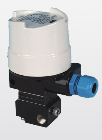
ABB MEASUREMENT & ANALYTICS TEIP11
ABB MEASUREMENT & ANALYTICS TEIP11
ABB MEASUREMENT & ANALYTICS TEIP11
Flow in air pressure
—
Proven and reliable concept
—
Integral mount design
• Small dimensions, low weight
—
Sturdy construction and solid functionality
• Influence of shock and vibration < 1 % bei 10 g
—
Variety of signal ranges
• Input e.g. 0 to 20 mA or 4 to 20 mA
• Output 0.2 to 1 bar (3 to 15 psi)
—
Wide temperature range
• From –40°(optional –55°) to 85° C
(–40° [optional 67°] to 185°F)
—
Approvals for explosion protection
• ATEX, FM / CSA, EACEx for intrinsically safe
and pressure-resistant operation
Concept
The TEIP11 signal converter converts standard electrical
signals, e.g. 4 to 20 mA to 0.2 to 1 bar (3 to 15 psi). It is
therefore a connecting link between electrical/electronic and
pneumatic systems. The signal conversion process is similar
to the patented force balance method.
Special features of the TEIP11 signal converter are its
relatively small dimensions and outstanding operational
stability when subject to shock and vibration. The converter
can be subjected to loads up to 10 g with less than 1% effect
on function.
The housing units are available in a variety of models to meet
your installation requirements. For potentially explosive
conditions, units that offer intrinsically safe operation or
pressure-resistant encapsulation are available with
international approval certificates for use worldwide.
Various ranges can be supplied on the input side and the
output side for signal conversion (see Specification on
page 4).
The device requires only compressed air 1.4 to 10 bar
(20 to 145 psi) for the power supply.
In order to ensure smaller dimensions and lower costs, an air
power stage is not included in the pneumatic unit.
This reduces the air capacity, meaning that the I/P signal
converter can only be used to control small-volume air
systems.
—
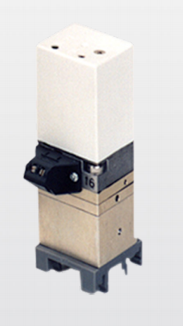
Designs
1 Control room housing for rail
mounting
2 Aluminum or stainless steel
field mount housing
Figure 1: TEIP 11 designs
Control room housing unit for rail mounting
The control room housing for rail mounting is the simplest
and lowest priced version of the I/P signal converter.
A mounting base that is compatible with all commercially
available EN rails is used for installation.
The housing unit with plastic cap has an IP 20 protection
rating.
Field mount housing
The field mount housing is suited for installation on-site or in
open areas. The housing can be made from plastic with IP
rating IP 54, from aluminum with IP rating IP 65 and from
stainless steel with IP rating IP 65. The housing is suited for
wall mounting and for 2 in pipe mounting
Specification
Input (electric)
Signal range
0 to 20 mA or 4 to 20 mA
0 to 10 mA or 10 to 20 mA
4 to 12 mA or 12 to 20 mA
(additional ranges available upon request)
Input resistance
Ri = 260 Ω at 20 °C (68 °F), Tk + 0.4 %/K
Overpressure limit
30 mA (for Ex devices see ).
Capacitance / inductance
Negligible
Output (pneumatic)
Signal range
0.2 to 1 bar (3 to 15 psi)
Air capacity
at supply air pressure [kg/h] [Nm3/h] [scfm]
1.4 bar (20 psi) 0.05 0.041 0.024
2.0 bar (30 psi) 0.07 0.057 0.033
4.0 bar (60 psi) 0.10 0.082 0.048
6.0 bar (90 psi) 0.16 0.130 0.076
10.0 bar(150 psi) 0.25 0.205 0.120
Power supply (pneumatic)
Instrument air
Free of oil, water, and dust acc. to DIN/ISO 8573-1
Pollution and oil content according to Class 3
Pressure dew point 10 K below operating temperature
Supply pressure
1.4 to 10 bar (20 to 145 psi)
Output signal
0.2 to 1 bar (3 to 15 psi)
Air consumption
Equivalent to air capacity
Transmission data and contributing factors
Characteristic curve
Linear, direct, or reverse action
Characteristic curve deviation
≤ 1 %
Hysteresis
≤ 0.3 %
Dead band
≤ 0.1 %
Temperature
≤ 1 % / 10 K within –20 to 85 °C (–4 to 185 °F)
≤ 2 % / 10 K within –55 to –20 °C (–67 to –4 °F)
Power supply
≤ 0.8 % at 1.4 to 2 bar (20 to 30 psi)
≤ 0.8 % at 2 to 3 bar (30 to 45 psi)
≤ 0.5 % to 3 to 10 bar (45 to 150 psi, each 1 bar [15 psi])
Mechanical vibration
≤ 1 % to 10 g and 20 to 80 Hz
Seismic vibration
Meets the requirements of DIN IEC 68-3-3 Class III for
strong and strongest earthquakes.
Mounting orientation
Zero point≤ 0.5 % at 90° change of position
Step response
10 to 90 % and 90 to 10 % 0.6 s
5 to 15 % and 15 to 5 % 0.25 s
45 to 55 % and 55 to 45 % 0.2 s
85 to 95 % and 95 to 85 % 0.15 s
EMC
Meets the requirements of EMC Directive 2014/30/EU
(increased interference immunity as per EN 50082-2 PR)
CE Marking
Complies with the EC directive for CE conformity
Operating conditions at installation site
Ambient temperature
Depending on the ordered model:
−40 to 85 °C (−40 to 185 °F)
–55 to 85 °C (–67 to 185 °F)
For Ex d:
−40 to 85 °C (−40 to 185 °F)
Mounting position
Any
Environmental capabilities
Climate class
GPF or FPF acc. to DIN 40040
Temperature:
–55 to 85 °C (–67 to 185 °F),
–45 to 85 °C (–49 to 185 °F)
Relative humidity for operation, storage, or transport:
75 % average, 95 % short-term,
no condensation
Expected service life of the device
With proper use and consideration of relevant environmental
conditions, the service life of the TEIP11 can reach
approx. 10 years.
Regular maintenance work and / or proper repairs by ABB
Service, along with the use of ABB spare parts, can extend the
service life of the TEIP11.
Design for rail mounting
Material / IP rating
IP 20 aluminum housing unit, with plastic cover
Mounting
Rail mounting:
EN 50022 - 35 × 7.5
EN 50035 - G 32
EN 50045 - 15 × 5
Electrical connection
2-pole screw terminal for 2.5 mm2 (14 AWG)
Pneumatic connection
⅛ NPT threaded hole for supply air and output
Weight
0.25 kg (0.55 lb)
Dimensions
Refer to Design for control room housing unit for rail
mounting on page 10
Specification
Design for field housing unit
(aluminum/stainless steel)
Material / IP rating
IP 65 aluminum or stainless steel housing unit
Surface
Aluminum housing,
painted with dual component coating,
lower section, black, RAL 9005,
screw-on cover, Pantone 420,
stainless steel housing unit,
electrolytically polished
Mounting
Wall or 2 in pipe mounting
With stainless steel mounting bracket (accessory)
Electrical connection
2-pole screw terminal for 2.5 mm2 (14 AWG) in the
housing, screw connection NPT ½ in for the cable entry.
For ATEX ‘intrinsically safe’:
Threaded hole NPT ½ in for the cable entry
For ATEX ‘Ex d’:
M20 × 1.5 threaded hole for cable entry at
FM/CSA
(Cable gland with Ex d approval available as an accessory
on request)
Pneumatic connection
¼ in NPT threaded hole for supply air and output
Weight
0.62 kg (1.37 lb) with aluminum housing unit
1.20 kg (2.65 lb) for stainless steel housings.
Dimensions
Refer to Design for aluminum or stainless steel field
mount housing on page 11.
Accessories
‘Ex d’ cable gland
Brass, with M20 × 1.5 thread
Stainless steel mounting bracket for wall mounting or
2 in pipe mounting
For aluminum or stainless steel field housing unit
Material for block mounting
Connection block for 4 signal converters,
End panel with central supply air connection ⅜ NPT,
dummy panel
ATEX
ATEX – ‘Ex d’ flameproof enclosure type of protection
Marking II 2G Ex d IIC T4/T5/T6 Gb
Type Examination Test Certificate DMT 02 ATEX E 121 X
Type DOC. 900771
Device class II 2G
Standards EN IEC 60079-0: 2018
(General requirements)
EN 60079-1: 2014
(Flameproof enclosure ‘d’)
System bus, computer interfaces
Current ≤ 50 mA
Pneumatic data
Supply pressure 1.4 to 10 bar (20 to 150 psi)
Output signal 0.2 to 1 bar (3 to 15 psi)
Thermal data T4: −40 °C < Tamb < 85 °C
T5: −40 °C < Tamb < 70 °C
T6: −40 °C < Tamb < 55 °C
Special conditions
The I/P signal converter may not be installed in areas in which
processes with very high electrostatic charges may occur.
Versions with an intrinsically safe control head may no longer
be operated as intrinsically safe if they have been previously
operated with the ‘flameproof enclosure’ type of protection
with a non-intrinsically safe power supply. The Ex designation
of the device should be updated accordingly.
The I/P signal converter is suited for use in an ambient
temperature range of –40 °C to maximum 85 °C.
If the I/P signal converter is used at an ambient temperature
above 60 °C or below –20 °C, use cable entries and cables
suited to an operating temperature that corresponds to the
maximum ambient temperature plus 10 K or that
corresponds to the minimum ambient temperature.
ATEX – ‘Ex ia’ instrinsic safety type of protection
Marking II 2G Ex ia IIC T6 resp. T4 Gb
Type Examination Test
Certificate
TÜV 99 ATEX 1487 X
Type TEIP11, Doc. 901068-SMDxxxx
TEIP11-PS, Doc. 901068-SMDxxxx
TEIP11-PS, Doc. 901069-SMDxxxx
Device class II 2G
Standards EN 60079-0:2009
EN 60079-11:2012
Temperature classes for the following versions:
TEIP11 Doc. 901068-SMD and TEIP11-PS Doc. 901068-SMD and
TEIP11-PS Doc. 901069-SMD
Temperature class Input current Ambient temperature
range
T4 120 mA –55 to 60 °C
T4 100 mA –55 to 85 °C
T6 60 mA –55 to 40 °C
TEIP11 Doc. 901068 and TEIP11-PS Doc. 901068 and TEIP11-PS
Doc. 901069
Temperature class Input current Ambient temperature
range
T6 50 mA –55 to 60 °C
T6 60 mA –55 to 55 °C
T5 60 mA –55 to 70 °C
T4 60 mA –55 to 85 °C
T5 100 mA –55 to 55 °C
T4 100 mA –55 to 85 °C
T5 120 mA –55 to 45 °C
T4 120 mA –55 to 80 °C
T4 150 mA –55 to 70 °C
Ex limit values
Li Ui Pi
50 mA 42.5 V 2.125 W
60 mA 38.8 V 2.328 W
100 mA 30 V 3.0 W
120 mA 28 V 3.36 W
150 mA 25.5 V 3.825 W
- YOKOGAWA
- Reliance
- ADVANCED
- SEW
- ProSoft
- WATLOW
- Kongsberg
- FANUC
- VSD
- DCS
- PLC
- man-machine
- Covid-19
- Energy and Gender
- Energy Access
- Renewable Integration
- Energy Subsidies
- Energy and Water
- Net zero emission
- Energy Security
- Critical Minerals
- A-B
- petroleum
- Mine scale
- Sewage treatment
- cement
- architecture
- Industrial information
- New energy
- Automobile market
- electricity
- Construction site
- HIMA
- ABB
- Rockwell
- Schneider Modicon
- Siemens
- xYCOM
- Yaskawa
- Woodward
- BOSCH Rexroth
- MOOG
- General Electric
- American NI
- Rolls-Royce
- CTI
- Honeywell
- EMERSON
- MAN
- GE
- TRICONEX
- Control Wave
- ALSTOM
- AMAT
- STUDER
- KONGSBERG
- MOTOROLA
- DANAHER MOTION
- Bentley
- Galil
- EATON
- MOLEX
- Triconex
- DEIF
- B&W
- ZYGO
- Aerotech
- DANFOSS
- KOLLMORGEN
- Beijer
- Endress+Hauser
- schneider
- Foxboro
- KB
- REXROTH
- YAMAHA
- Johnson
- Westinghouse
- WAGO
- TOSHIBA
- TEKTRONIX
- BENDER
- BMCM
- SMC
- HITACHI
- HIRSCHMANN
- XP POWER
- Baldor
- Meggitt
- SHINKAWA
- Other Brands
- UniOP
- KUKA
- IBA
- Beckhoff
- ADLINK
51
-
Beckhoff EP9224-0037 - 4-Channel Power Distribution Box EtherCAT
-
Beckhoff CX2900-0026 - Solid State Flash Memory Card 20GB CFast
-
Beckhoff BK7500 - SERCOS Interface Fieldbus Bus Coupler Terminal
-
Beckhoff Ep2328-0002 - 4-Channel Input 4-Channel Output EtherCAT Box IP67
-
Beckhoff CX1020-0111 - Controller Kit Combo Interface Modules
-
B&R X20AI2237 - X20 System Analog Input Interface Module
-
Beckhoff CP2221-0010 - Multi-Touch Built-In Panel PC Touchscreen
-
Beckhoff CX1500-M310 - Fieldbus Master Interface Module 24V
-
Beckhoff CX2100-0904 - Power Charging Module Smart UPS Extension
-
Beckhoff CP3918-0000 - Multi-Touch Control Panel 18.5-Inch Monitor
-
Beckhoff CP2915-0000 - 15-Inch Multi-Touch Built-In Control Panel
-
Beckhoff CP7037-1027 - HMI Industrial Control Panel Built-In PC
-
Beckhoff EL3152 - 2-Channel Analog Input Terminal 4-20mA EtherCAT
-
Beckhoff CP6607-0000-0020 - 5.7-Inch Built-In Panel PC HMI Touch
-
Beckhoff EJ1809-0000 - 16-Channel Digital Input Pluggable Signal Level Terminal
-
Beckhoff AM8563-0N10-0000 - Synchronous Servo Motor
-
Beckhoff AX2006-S60600-520 - Compact Servo Drive Inverter
-
Beckhoff AM8053-0K20-0000 - Servo Motor with Planetary Gearbox AG3210
-
Beckhoff AM8042-0FH1-0000 - Synchronous Servo Motor
-
Rexroth R911338600 - IndraControl V HMI Terminal Beckhoff PCI Card FC9002
-
Beckhoff AX5125-0000 - 3 Phase Industrial Servo Drive 1000Hz
-
Beckhoff EP2328-0002 - 4-Channel Digital Input 4-Channel Output EtherCAT Box
-
B&R 7CP476-02 - System 2005 RTD CPU Module 3IF681.86 Interface
-
Beckhoff AX8620-0000-0000 - Power Supply Module Axis Drive System
-
Beckhoff CX1010-0111 - PLC Module CPU Controller 24V
-
Beckhoff AM8043-0H10-0000 - Synchronous Servo Motor
-
Beckhoff C6240-1009 - Control Cabinet Industrial PC Mainframe
-
Beckhoff BX8000-0000 - Bus Terminal Controller HW 4.4 Standalone
-
Beckhoff CP7721-1089-0020 - 12.1-Inch Touch Screen HMI Panel PC
-
Beckhoff CP7132-0001 - Industrial Built-In Panel PC Screen
-
Beckhoff CP2912-0010 - Multi-Touch Built-In Control Panel Display
-
Beckhoff CP2915-0000 - 15-Inch Multi-Touch Built-In Control Panel
-
Beckhoff AM8532-1EN0-0000 - Synchronous Servo Motor
-
Beckhoff AX5203-0000 - 2-Channel Digital Compact Servo Drive
-
Beckhoff CX2020-0141 - Embedded PC Core CPU Module
-
Beckhoff CP6832-0002-0010 - Built-In Industrial Control Panel Display
-
Beckhoff CX5020-0112 - Embedded PC CPU Control Module
-
Beckhoff CX5140-0175 - 4GB Embedded PC CPU Unit 24V
-
Beckhoff EL3681-0030 - Digital Multimeter Calibration Terminal EtherCAT
-
Beckhoff CP7201-1000-0000 - Industrial PC Touch Screen HMI Monitor
-
Beckhoff CP7232-1001-0000 - Industrial Panel PC Touch Screen
-
Beckhoff C6930-1032-0040 - Control Cabinet Industrial PC System
-
Beckhoff AX5125-0000 - 3 Phase Industrial Servo Drive 1000Hz
-
Beckhoff CP3916-1424-0000 - Multi-Touch Built-In Control Panel
-
B&R 1900071142 - Lemoine Fieldbus Communication Interface Module
-
Beckhoff EL2872 - 16-Channel Ribbon Cable Digital Output Terminal
-
Beckhoff CX2030-0120 - Embedded PC CPU Base Module Controller
-
Beckhoff CP3919-0000 - 19-Inch Multi-Touch Control Panel Touchscreen
-
Beckhoff AX5101-0000-0202 - Servo Driver Compact Intelligent Drive 180V
-
Beckhoff CX5130-0135 - Embedded PC Controller Module
-
Beckhoff CP3719-1061-0010 - Multi-Touch Panel PC Outer Housing Enclosure
-
Beckhoff CP3919-1033-0000 - 19-Inch Touch Industrial Panel Keyboard
-
Beckhoff CX5020-0111 - Embedded PC PLC CPU Module
-
Beckhoff FC5102-0000 - 2-Channel CANopen PCI Control Board Card
-
Beckhoff CX9001-1101 - Embedded PC CPU Network I/O System Module
-
Beckhoff CX1100-0920 - Smart Position Sensor Interface Module
-
B&R 4P3040.01-490 - Operator Panel PLC Interface Communication Module
-
Beckhoff CP2612-0000 - Dual-Touch Built-In Panel PC HMI
-
Beckhoff CP7002-1043-0010 - Touchscreen Display HMI Panel Terminal
-
Beckhoff CX9020-0115 - Embedded PC Controller Module
-
Beckhoff CX5140-0155 - 4GB Embedded PC CPU Module Die Industry
-
B&R 7DI435.7 - System 2005 Universal Digital Input Output Module
-
Bihl+Wiedemann BWU1568 - AS-i Master to Profibus Gateway Module
-
Beckhoff C6920-0070 - Control Cabinet Industrial PC 8GB Win 10
-
B&R X20AI2322 - 2-Channel Temperature Analog Input Module
-
Beckhoff CP2912-0000 - 12-Inch Touchscreen Display Monitor Screen
-
Beckhoff CP6022-1001-0010 - 15-Inch Built-In Control Panel
-
Beckhoff AM8031-0D10-0000 - Synchronous Servo Motor
-
Beckhoff CX5010-0111 - Embedded PC Controller CPU Module
-
Beckhoff CP7232-1000-0000 - Industrial Panel PC Touch Display Screen
-
Beckhoff CP7802-0011-0000 - 15-Inch Industrial Touchscreen Control Panel
-
Beckhoff C6320 - Control Cabinet Industrial PC
-
Beckhoff CX1030-0012 - Basic CPU Module Windows CE 6.0
-
Beckhoff CP2919-0000 - Installation Multi-Touch Control Panel
-
Beckhoff CX1020-0000 - Controller Set Stack System Pack
-
B&R 3DO480.6 - System 2005 Digital Output Module
-
Beckhoff EL3101 - 1-Channel Analog Input Terminal Differential +/-10V
-
Beckhoff AX8108-0200-0000 - Axis Feed Module Servo Drive
-
Beckhoff CP7802-1241-0010 - 15-Inch Industrial Touchscreen Control Panel
-
Beckhoff FC2002-0000 - 2-Channel Lightbus Data Acquisition PCI Card
-
Beckhoff CX5120-0155 - 2GB Embedded PC Intel Atom Controller
-
Beckhoff Cx9020-0111 - 1GB Basic CPU Module Embedded PC
-
Beckhoff CP6901-0001-0000 - 12-Inch Economy Built-In Control Panel
-
Beckhoff CX9020-0111 - Embedded PC CPU Basic Module
-
Beckhoff CX5130-0100 - 4GB Embedded PC CPU Module
-
Beckhoff CP2715-0010 - Multi-Touch Built-In Panel PC
-
Beckhoff CX2033-0175 - Embedded PC CPU Module Core i7
-
Beckhoff CP7201-1000-0000 - 12-Inch Touchscreen Panel PC AMAT Green Box
-
Beckhoff EL4038 - 8-Channel Analog Output Terminal 0-10V EtherCAT
-
Beckhoff CP6802-0000-0000 - Built-In Control Panel HMI Screen
-
Beckhoff CP6500-1012-0060 - Control Cabinet PC Interface Unit
-
Beckhoff FC5202-0000 - 2-Channel DeviceNet Master PCI Interface Card
-
Beckhoff CP6606-0001-0020 - 7-Inch Economy Panel PC Touch
-
Beckhoff CP2921-0010 - Multi-Touch Integrated Control Panel Display
-
Beckhoff CP7802-0001-0010 - 15-Inch Touch Screen Control Panel HMI
-
Beckhoff C6920-0050 - Control Cabinet Industrial PC
-
Beckhoff BK9105 - EtherNet/IP Bus Coupler Network Interface
-
Beckhoff 31 Modules - Bus Terminal Slice I/O Lot Assortment
-
Beckhoff CX2020-0120 - Embedded PC Basic CPU Module 8GB CFast Card
-
Beckhoff CP7001-0000 - HMI Control Panel Touch Screen
-
B&R 7EX484.50-1 - System 2005 Controller Base Module Slots
-
Beckhoff EK1322 - 2-Port EtherCAT P Extension Feed-In Terminal
-
Beckhoff CP6606-0001-0020 - 7-Inch Single-Touch Economy Panel PC
-
Beckhoff CP6607-0001-0000 - Economy Installation Operator Panel PC 5.7-Inch
-
Beckhoff AX5103-0000-0200 - Digital Compact Servo Driver 3 Phase
-
Beckhoff CP7802-0001-0010 - 15-Inch Touch Screen Control Panel
-
Beckhoff AX8620 - Power Supply Module Axis System
-
Beckhoff CX2030-0121 - Embedded PC Controller Module
-
Beckhoff CP6606-0001-0020 - 7-Inch Economy Panel PC Touch Screen
-
Beckhoff CX2030-0121 - Embedded PC CPU Module Windows Standard 7
-
Beckhoff BX3100-0000 - PROFIBUS DP Bus Terminal Controller
-
Beckhoff CX1020-0000 - Controller Set with Power Supply Unit
-
Beckhoff EK1100 - EtherCAT Coupler Terminal Module Set
-
Beckhoff CP7002-1043-0010 - HMI Display Panel with Control Panel Bracket
-
Beckhoff AM8031-0D10-0000 - Synchronous Servo Motor
-
Beckhoff CX5130-0175 - Embedded PC 4GB RAM Controller
-
Beckhoff CX5130-0155 - Embedded PC Automation Controller
-
Beckhoff C6930-0010 - Control Cabinet Industrial PC Core Duo
-
Beckhoff CP3924-0000 - Multi-Touch Control Panel Display
-
Beckhoff AM8023-0F20-0000 - Synchronous Servo Motor
-
B&R KL3362 - Bus Terminal Thermocouple Input Module
-
Beckhoff AL2006-0000-0000 - Linear Servo Motor Three Phase
-
Beckhoff CX5140-0155 - Embedded PC CPU Controller Module
-
Beckhoff FC9002 - Ethernet PCI Network Interface Card
-
Beckhoff CP7203-0021-0040 - Built-In Panel PC 19-Inch Touch Screen
-
Beckhoff C6930-0020 - Control Cabinet Industrial PC HDD CF Card
-
Beckhoff CX2900-0033 - Memory Card CFast Storage
-
Beckhoff CP6201-0001-0020 - Built-In Panel PC Display

K-JIANG

Add: Jimei North Road, Jimei District, Xiamen, Fujian, China
Tell:+86-15305925923