
K-WANG


TOSHIBA V200 series programmable logic controller
Target audience: Qualified Person operators are required, who possess electrical equipment installation/maintenance skills and have received safety training (in compliance with NFPA 70E standards).
TOSHIBA V200 series programmable logic controller
Document Overview and Product Positioning
1.1 Core positioning of the document
Document number: UM-V200-E001, initial version released in January 2012, is a technical guide for the entire lifecycle of V200 series PLCs, covering the entire process from unboxing installation to fault maintenance.
Target audience: Qualified Person operators are required, who possess electrical equipment installation/maintenance skills and have received safety training (in compliance with NFPA 70E standards).
1.2 Core Product Parameters
The V200 series is divided into basic models and extended models. The core parameters of the basic models are compared as follows:
Basic model, local I/O configuration, expansion capability, communication interface, high-speed counting capability, size (mm), weight (gm)
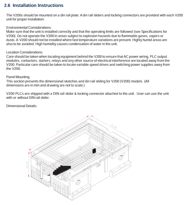
GPU288 * 3S 8-in (digital)/8-out (6 relays+2 transistors) supports 8 expansion modules COM1 (RS232/RS485), COM2 (RS485), USB 2-channel single-phase (50kHz), 1-channel orthogonal (5kHz) 100 × 35 × 70 200
GPU232 * 3S 16 in (digital)/16 out (digital) without expandability COM1 (RS232), COM2 (RS485), USB 2-channel single-phase (50kHz) 155 × 102 180
GPU200 * 3S without local I/O support 8 expansion modules COM1 (RS232/RS485), Ethernet, USB 2-channel single-phase (100kHz) 100 × 35 × 70 200
The expansion models include digital expansion (such as GDI216S: 16 digital inputs) and analog expansion (such as GAD208S: 8 analog inputs), supporting flexible configuration of I/O points.
Safety operation standards (top priority)
2.1 Definition of Warning Signs
The document specifies the risk level through "identification+text", and all identification is printed on the equipment body and key positions in the manual:
Core meaning of warning signs Typical scenarios
DANGER operational errors can result in death or serious injury (such as high-voltage electric shock, fire). Opening terminal covers and contacting high-voltage components when powered on
Incorrect operation of Warning may result in serious injury or equipment damage (such as device falling or burning). Handheld terminal cover handling or touching the heat sink
CAUTION operation errors can result in minor injuries or equipment malfunctions (such as loose terminals, electrostatic damage), ungrounded operations, and wiring errors
2.2 Core Security Rules
Prohibited operation list:
Do not open the power terminal cover (which contains 24VDC high-voltage components) when powered on.
Do not insert foreign objects such as wires, tools, dust, etc. into the ventilation openings or terminal slots of the equipment (to prevent short circuits).
It is prohibited to disassemble or modify hardware without authorization (such as replacing non original capacitors), as this will result in warranty failure and safety risks.
It is prohibited to use unverified models in explosion-proof environments (such as flammable gas areas).
Mandatory operation checklist:
Before installation/maintenance, it is necessary to read the manual thoroughly and confirm that the operator is a Qualified Person.
After power failure, wait for at least 15 minutes and use a multimeter with 800Vdc or higher to check that the voltage of the DC main circuit (PA/+and PC/-) is ≤ 45V before operation.
Reliable grounding is required: D-type grounding is used for 240V level, C-type grounding is used for 500/600V level, grounding resistance is ≤ 4 Ω, and the grounding wire specification is not less than the main circuit wire.
When enabling the Auto restart function, a warning label stating 'Possible sudden restart' should be affixed next to the device.

Hardware installation and wiring
3.1 Installation environment requirements
The allowable range of environmental indicators and the prohibited range
Environmental temperature 0 ℃~55 ℃ (operation), -20 ℃~85 ℃ (storage) exceeding 55 ℃ (triggering overheating protection), below -20 ℃ (capacitor failure)
Relative humidity 20%~90% (no condensation) Condensation environment, humidity>90% (causing short circuit)
Vibration requirement ≤ 5.9m/s ² (5-150Hz) exceeding 5.9m/s ² (additional anti vibration pads need to be installed)
Environmental cleanliness without dust, metal powder, corrosive gas, dense dust, and oil mist environment (blocking heat dissipation)
3.2 Wiring specifications
Main circuit wiring:
Power input: 24VDC ± 15%, requires separate wiring (threaded separately from the control circuit), terminal screw torque: M3 is 0.5N · m, M4 is 1.4N · m.
Digital input: 24VDC, current per point 5mA (high-speed input 20mA), input impedance 5.4k Ω (high-speed input 1.2k Ω).
Digital output: Relay type (230V/2A, 30VDC/2A), transistor type (24VDC/0.5A), output terminals need to be wired according to the "set of common terminals every 4 points".
Communication wiring:
RS485: 2-wire system, maximum transmission distance of 1200m, supports 32 nodes, requires 120 Ω terminal resistors to be connected at both ends of the bus.
USB: For programming only, using USB 2.0 Type B interface, cable length ≤ 2m.
Ethernet (GPU200 * 3S): RJ45 interface, supports 10/100Mbps adaptive, requires shielded Ethernet cable.
Software Configuration and Programming
4.1 OIL DS software installation
System requirements:
Operating systems Windows 2000 (SP4), XP (SP2), Vista
Processor ≥ 800MHz (Vista requires ≥ 1GHz)
Memory ≥ 256MB (Vista requires ≥ 1GB)
Hard disk space of 800MB (including 200MB. NET Framework)
Display resolution 1024 × 768 (16 bit high color)
Installation steps:
Run Setup. exe and select the installation path (default C: Program Files OIL DS).
Wait for the installation to complete and start the software through "Start → Program → OIL DS".
When uninstalling, execute through "Start → Program → OIL DS → Uninstall OIL DS".
4.2 Ladder diagram programming
Core process:
New project: Select V200 model (such as GPU288 * 3S), configure project name and storage path.
Define Tag Database: Assign I/O addresses (such as X0000 corresponding to digital input 1) and register types (input X/output Y/configuration MW).
Edit ladder diagram: Drag and drop "normally open contact (NO)", "coil", "function block (such as MOV-W)" to construct logic, supporting subroutines and interrupt programs.
Compile and Download: Press F9 to compile (if there are no errors, it will display "Compilation Successful"), and download it to the PLC via USB/RS485.
Program type:
Main program: It runs in a loop during normal operation and needs to end with the "END" instruction.
Subroutine: Called with the "CALL" instruction and returned with the "RET" instruction.
Interrupt program: Timer interrupt (5-1000ms), I/O interrupt (triggered by high-speed counting), must end with the "IRET" instruction.
Detailed explanation of special I/O functions
5.1 High speed counter
Function type:
Type Input Channel Maximum Frequency Counting Range Application Scenarios
Single phase counter 2-channel (X000/X001) 50kHz 0~4294967295 (32-bit) pulse counting (such as encoder)
Single phase speed counter 2-channel (X000/X001) 50kHz 0~4294967295 (32-bit) speed measurement (fixed sampling time)
Orthogonal biphasic counter 1 channel (X000=phase A, X001=phase B) 5kHz 0~4294967295 (32-bit) bidirectional counting (such as motor forward and reverse rotation)
Configuration register: Select the function mode through MW10 (high-speed input configuration register), such as "MW10=0x0010" to enable the single-phase counter.
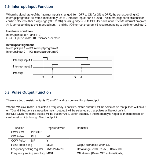
5.2 Pulse/PWM output
Pulse output:
Channel: 1 channel (Y0=CW/PLS, Y1=CW/DIR).
Frequency range: 50~5000Hz, supports positive and negative frequencies (corresponding to positive and negative reversals).
Configuration: Set MW11 (pulse output configuration register) to "0x0001" enabled, and set the frequency for MW22/MW23.
PWM output:
Channel: 1 channel (Y0).
Parameters: frequency 50~5000Hz, duty cycle 0~100% (1% step size).
Configuration: MW11 is set to "0x0000" enabled, and MW24/MW25 is set to duty cycle.
5.3 Interrupt Input
Channel: 2 channels (X001=Interrupt 1, X002=Interrupt 2).
Trigger method: Rising edge (OFF → ON) or falling edge (ON → OFF), configured through MW10's Bit4/Bit5.
Response time: Interrupt signal ON/OFF pulse width ≥ 100 μ s, ensuring stable recognition of PLC.
Troubleshooting and Maintenance
6.1 Troubleshooting process
Power failure (PWR light not on):
Check the power wiring: whether the terminals are loose and whether the voltage is 24VDC ± 15%.
Remove the expansion module: If the PWR light is restored, troubleshoot the expansion module.
Check internal power supply: If it still doesn't light up, replace the PLC host.
CPU malfunction (RUN light not on):
Check the mode switch: whether it is in the "RUN" position, switch to "RUN" and retry.
Check the ERR light: If the ERR light is on, read the fault code through OIL DS (such as "WDT Error" indicating watchdog timeout).
Re download firmware: If the RUN/ERR lights flash simultaneously, the firmware is damaged and needs to be re downloaded.
Input/output fault (abnormal I/O status):
Check the wiring: Check if the terminal screws are loose and if the wires are damaged.
Monitoring I/O status: Check the X/Y status through the "Monitor" function of OIL DS to determine whether it is a hardware or program issue.
Replace module: If one of the I/O channels is consistently abnormal, replace the corresponding expansion module.
6.2 Maintenance Standards
Daily inspection (daily):
Appearance: The LED status is normal (PWR is constantly on, flashing when RUN is running), and there is no abnormal sound/odor.
Environment: Temperature 0~55 ℃, humidity 20%~90%, no dust accumulation.
Regular inspection (every 6 months):
Cleaning: Use compressed air (≤ 0.3MPa) to clean the dust from the cooling fins and ventilation openings.
Wiring: Tighten all terminal screws (to the specified torque) and check the insulation layer of the wire.
Insulation test: After power failure, use a 500V megohmmeter to test the insulation resistance of the main circuit to ground to be ≥ 1M Ω.
Suggestions for spare parts:
Spare parts names, suggested quantities, and notes
Minimize system downtime with one V200 CPU
1 commonly used I/O module each, such as GDI216S (digital input), GAD208S (analog input)
1 programming cable for troubleshooting and program download
Replace 2 cooling fans after 20000 hours of cumulative operation
- YOKOGAWA
- Reliance
- ADVANCED
- SEW
- ProSoft
- WATLOW
- Kongsberg
- FANUC
- VSD
- DCS
- PLC
- man-machine
- Covid-19
- Energy and Gender
- Energy Access
- Renewable Integration
- Energy Subsidies
- Energy and Water
- Net zero emission
- Energy Security
- Critical Minerals
- A-B
- petroleum
- Mine scale
- Sewage treatment
- cement
- architecture
- Industrial information
- New energy
- Automobile market
- electricity
- Construction site
- HIMA
- ABB
- Rockwell
- Schneider Modicon
- Siemens
- xYCOM
- Yaskawa
- Woodward
- BOSCH Rexroth
- MOOG
- General Electric
- American NI
- Rolls-Royce
- CTI
- Honeywell
- EMERSON
- MAN
- GE
- TRICONEX
- Control Wave
- ALSTOM
- AMAT
- STUDER
- KONGSBERG
- MOTOROLA
- DANAHER MOTION
- Bentley
- Galil
- EATON
- MOLEX
- Triconex
- DEIF
- B&W
- ZYGO
- Aerotech
- DANFOSS
- KOLLMORGEN
- Beijer
- Endress+Hauser
- schneider
- Foxboro
- KB
- REXROTH
- YAMAHA
- Johnson
- Westinghouse
- WAGO
- TOSHIBA
- TEKTRONIX
- BENDER
- BMCM
- SMC
- HITACHI
- HIRSCHMANN
- XP POWER
- Baldor
- Meggitt
- SHINKAWA
- Other Brands
- UniOP
- KUKA
- IBA
- Beckhoff
-
ADLINK CPCI-6860A - 51-31310-OB10 industrial motherboard CompactPCI SBC
-
ADLINK AmITX-SL-G-H110 - 51-7A104-0A30 Mini-ITX Industrial Motherboard
-
ADLINK PXI-2005-003 - CPCI Industrial PC Data Acquisition Card Multi-Function DAQ
-
ADLINK DININ-814M - 51-14032-0A3D SCSI-100P cable connection Interface Terminal Board
-
ADLINK CPCI-3920NA/C2D15/M1G - 3U CompactPCI Intel Core 2 Duo Single Board Computer
-
ADLINK PCIE-8560 - 51-18014-0A20 Communication Card High Speed DAQ
-
ADLINK PCI-C154+ - Motion Control Card 4-axis Motion Controller Board
-
ADLINK PCI-RTV24 - image capture card Analog Video Frame Grabber
-
ADLINK NuPRO-842LV/P - 51-41360-0B30 Industrial Motherboard CPU Board
-
ADLINK cBP-3208/3208R - CPCI Board 3U 8-Slot CompactPCI Backplane
-
ADLINK PCI-8164 - 4-Axis Motion Controller PCI Card 51-12406-0A40
-
ADLINK PCIe-GIE64+ - 4-CH GigE Vision PoE+ Frame Grabber Video Capture Card
-
ADLINK CPCI-6860 / 6860A - CompactPCI Dual Xeon Single Board Computer
-
ADLINK IEC-915GV - REV 1.1 Industrial motherboard CPU Board
-
ADLINK ND-6520 - Technology RS-232 to RS-422RS-485 Converter NuDAM Module
-
ADLINK RTV-24 / PCI-MP4S - 51-12519-1C30 4-Channel Real Time Video Capture Board
-
ADLINK cPCI-6910 / cPCI-6910AM/M1G - cPCI-6910AM/DXL16/M1G/S80G(G)-3120 BOARD CompactPCI SBC
-
ADLINK NUPRO-A40H - Linghua 51-41807-1A30 Industrial Control Computer Motherboard
-
ADLINK USB-3488A - USB to GPIB INTERFACE USB-3488A(G) Controller Module
-
ADLINK PCI-8134A - motion control card 4-Axis Controller Card
-
ADLINK PCI-7432 - Board 32-Channel input / 32-output Isolated Digital I/O PCI Card
-
ADLINK PCI-8134A - 51-12421-0A10 motion controller card tested
-
ADLINK LPCIe-7230 - 32 CH Isolated Input/output Card 2 Interrupts Low Profile PCIe
-
ADLINK NuPRO-E340 - industrial computer motherboard 51-47807-0A30 PICMG 1.3 SHB
-
ADLINK PCI-7434 - High-speed Digital Acquisition Card 64-CH Isolated DO Card
-
ADLINK NuPRO-E330 - 51-41805-0A20 Indsutrial Board SHB Single Board Computer
-
ADLINK PCI-7248 - OPTO-22 48 CHANNEL DIO DIGITAL TTL/DTL I/O 51-12006-0A40 GP
-
ADLINK PCI-8134 - Motion control card 4-Axis Controller Card
-
ADLINK AMP-208C - Movimiento Control Tarjeta 51-12420-1A20 W/Expansión & Breakout
-
ADLINK PCI-8164 - 51-12406-0A40 PCB Board 4-Axis Motion Controller Card
-
ADLINK DIN-68Y-SGII / DIN-68M-J3A - Terminal Board Connector Interface Block
-
ADLINK PCIe-7432 - Technology 51-18402-0A10 PCIe Card With High Input Range
-
ADLINK PCI-8144 / PCI-8144N - Motion control card 4-Axis Stepper Controller Card
-
ADLINK HSL-HUB3/REPEATER - HIGH SPEED LINK EXTENSION MODULES Distributed Hub Module
-
ADLINK ND-6017 - Data Logging + Acquisition 8CH A/D input Mod NuDAM Module
-
ADLINK LPCIe-7250 - data acquisition card Low Profile 8-CH Relay Output Card
-
ADLINK PCI-7432 - I/O card 64-CH Isolated Digital Input Output PCI Card
-
ADLINK IMB-M43H - industrial control computer motherboard Q87 Chip Micro-ATX
-
ADLINK MP-C154 - Motion control Card 4-Axis Motion Controller Board
-
ADLINK PCI-RTV24 - image capture card Video Frame Grabber Card
-
ADLINK PCI-7250 - 8-CH Relay Output & 8-CH Isolated DI Card
-
ADLINK PCI-6308V - 8-CH 12-Bit Isolated Analog Output PCI Card PCB-I-E-1148=6EX2
-
ADLINK PCI-7248 - capture card 48-CH Opto-22 Compatible DIO Card
-
ADLINK HSL-AI16A02-M-VV - Analog Input Output Distributed Module
-
ADLINK NuPRO-A301 - Rev:1.4 NUPRO-A301 PICMG Full-Size Single Board Computer
-
ADLINK PCI-6208V-GL - 8-CH Voltage Analog Output PCI Card
-
ADLINK PCI-8134A - 51-12421-0A10 4-Axis Motion Controller Card
-
ADLINK MNET-S23 - TECHNOLOGY MNET S23 - SERVO DRIVER CONTROL MODULE
-
ADLINK M-342 - ATX I3 I5 I7 Q67 Industrial Motherboard
-
ADLINK NUPRO-780 - Industrial Motherboard CPU Board PICMG SBC
-
ADLINK MP-C154 / MP-C152 - 4-Axis Motion Control Card Pulse-Train Controller
-
ADLINK NuPRO-935A/LV10B0 - Motherboard 51-41802-0A10 GP w/RAM Industrial Control Board
-
ADLINK MP-C154 - Motion control card 4-Axis Motion Controller Mainboard
-
ADLINK PCI-7250 - PCI Acquisition Card 8-CH Relay Output Isolated DI Card
-
ADLINK ACL-7124 - Technology Inc.24 DIO Card Digital Input Output Card
-
ADLINK PCI-8554 A2 - Timer/Counter Data Acquisition Card
-
ADLINK DIN-825-GP4 - Terminal Block Interface Board Breakout Module
-
ADLINK NuPR0-761 - REV:1.1 Industrial motherboard Full-Size PICMG SBC
-
ADLINK MXE-1401/M8G (G) - Matrix Fanless Embedded Computer Industrial PC
-
ADLINK HSL-DI16DO16-UD-NN - Digital 16 Channel I/O Mod Distributed I/O Module
-
ADLINK ND6520 - NUDAM INTELLIGENT DA&C MODULE RS232-RS-422/RS485 CONVERTOR
-
ADLINK NUPRO-761 - REV:1.1 Industrial Motherboard CPU Board
-
ADLINK AMP-208C - Motion Control Card 51-12420-1A20 DSP-based 8-axis
-
ADLINK NuPRO-A301REV 1.4 - with packaging industrial computer motherboard PICMG SBC
-
ADLINK PCM-9112+ - 51-12300-0A2 industrial motherboard Multi-Function DAQ PC/104 Module
-
ADLINK PCM-7250+ - 8-CH Relay Outputs & 8-CH Isolated DI Module PC/104
-
ADLINK PCI-RTV24 - Image capture card Analog Video Frame Grabber
-
ADLINK PCI-8134 - Motion Controller PCI Card 4-Axis Controller Board
-
ADLINK PCI-7432 - Isolated Digital I/O PCI Card
-
ADLINK PCI-8554 A2 - acquisition card Timer/Counter Card
-
ADLINK PCI-8132 - Rev.A2 2-Axis Servo & Stepper Motion Controller Card
-
ADLINK PCI-8132 - Data Acquisition card 2-Axis Motion Controller Card
-
ADLINK EBP-13E4 - 51-46703-0A30 Industrial Backplane Board Passive Backplane
-
ADLINK PCI-800L - Electronic Card Interface Controller Card
-
ADLINK PCIe-GIE72 - 51-18531-0A10 PCB Board GigE Vision Frame Grabber
-
ADLINK DAQ-2010(G)-OOBO - Simultaneous-Sampling Multi-Function DAQ Card
-
ADLINK PCI-9112 - REV.B1 Multifunction DAQ Card Data Acquisition Card
-
ADLINK PCI-7230 - 51-12003-DA60 32-CH Isolated Digital I/O Card
-
ADLINK PCI-7432 - Data Acquisition Card Isolated Digital I/O PCI Card
-
ADLINK ETX-AT-N270-18/LXE - 51-71111-0A20 ETX CPU Module Motherboard
-
ADLINK HSL-DI32-UD-N - DIGITAL INPUT 32 POINTS MODULE Distributed I/O
-
ADLINK AMP-204C - Motion Control card DSP-Based 4-Axis Advanced Controller
-
ADLINK MNET-4XMOG-0050 - Four-axis Motion Controller Distributed Motion Module
-
ADLINK AMP-204C - Motion control card DSP-Based 4-Axis Pulse-Train Controller
-
ADLINK PCI-7442 - Switch card 64-Channel Datalogging & Acquisition Card
-
ADLINK M-302 - Industrial control motherboard ATX PC Board
-
ADLINK NUPRO-852 / NUPRO-852LV - Industrial motherboard Single Board Computer
-
ADLINK PCI-8134 - REV.B1. 4-Axis Motion Controller Card
-
ADLINK PCI-GIE62 + - 51-18502-0A20 2-CH GigE Vision Frame Grabber PoE Card
-
ADLINK PCI-MPG24 - 51-12523-0B20 MPEG4 Card Video Compression Hardware
-
ADLINK HSL-TB32-M-DIN - 32-CH I/O TERMINAL W/ HSL-AI16AO2-M-VV MODULE
-
ADLINK PCI-M114-GL - PCB Ver 2.1 Motion Controller Axis Card
-
ADLINK IMB-M40H - SYM76996H61 motherboard Industrial Computer Mainboard
-
ADLINK NUPRO-A40H - 51-41807-1A20 industrial control motherboard H61 Chip
-
ADLINK PCI-M114-GL - Axis Card Data Acquisition Card PCB VER2.2 Motion Controller
-
ADLINK PCI-8134 - Motion Controller PCI Card 4-Axis Controller Board
-
ADLINK PCI-8102 - Motion control card 2-Axis Servo & Stepper Controller
-
ADLINK NuPRO-841REV:3.0 - motherboard Industrial Control PC Board
-
ADLINK HSL-TB32-U-DIN REV A1 - Breakout Terminal Board Field I/O Module
-
ADLINK AMP-204C - Motion Control card DSP-Based 4-Axis Pulse-Train Controller
-
ADLINK NUPRO-A40H - 51-41807-1A20 industrial control motherboard H61 PC Board
-
ADLINK PCI-6308A / PCI-6308V - 51-12202-0A50 Isolated Analog Output Card
-
ADLINK AMP-204C - DSP-Based 4-Axis Advanced Pulse-Train Motion Controller
-
ADLINK PCI-7434 - Technology 64-Channel Isolated Digital I/O PCI Cards
-
ADLINK CPCI-6840 / CPCI-6840V / PM16/M1G-12G0 - CompactPCI Single Board Computer CPU Module
-
ADLINK PCIE-GIE74 - Motherboard Video Capture Card 51-18531-0A10 Frame Grabber
-
ADLINK NuPRO-E330 - industrial computer equipment motherboard Control Mainboard
-
ADLINK AMP-208C / 51-12420-1A20 - Motion Control Card W/ Expansion & Breakout Board
-
ADLINK HPCI-14S12U - industrial computer baseboard Passive Backplane 14 Slots
-
ADLINK PCI-8164 - 4-Axis Motion Controller PCI Card W/ 1x Cable, 1x Breakout Box
-
ADLINK PCIe-RTV24 - 51-18016-0A20 Image Acquisition Video Capture Card
-
ADLINK M-342 - 5 PCI ATX Motherboard Industrial PC Mainboard
-
ADLINK PCI-FIW64 - 4/2 Channel IEEE1394B Image Capture Card FireWire Frame Grabber
-
ADLINK PCI-7432 - digital IO card 64-CH Isolated Digital Input Output Card
-
ADLINK 51-12001-0C20 - Circuit Board PCI-7200 Data Acquisition Controller Card
-
ADLINK PXI-3920 - PXI 3U cPCI Industrial Controller Embedded System CPU Board
-
ADLINK NuPRO-841REV:2.0 - motherboard Industrial Control PC Board
-
ADLINK NuPro-E330 - 51-41805-0A20 PCB Industrial Control Computer Motherboard
-
ADLINK PCI-RTV24 - Image capture card Analog Video Frame Grabber
-
ADLINK PCI-7442 - Switch card 64-Channel Datalogging & Acquisition Card
-
ADLINK HPX-13S4 - device baseboard Passive Backplane Riser Card
-
ADLINK PCI-9112 REV A.1 - Multi Function DA&C Board Data Acquisition Card
-
ADLINK PCI-7248 - 51-12006-0A40 Card Control 48-CH Digital I/O Module
-
ADLINK CPCI-6860 / 6860A - motherboard CompactPCI Dual Xeon Single Board Computer
-
ADLINK DPAC-3020-11(G) - Embedded PC Automation Controller Machine Control Board
-
ADLINK NuPRO-841 REV:1.0 - industrial control motherboard CPU Board
-
ADLINK MNET-4XMOG-0050 - Four-axis Motion Controller MNET Motion Control Card
-
ADLINK ETX-AT-N270-18/LXE - 51-71111-0A20 ETX CPU Module Motherboard

K-JIANG

Add: Jimei North Road, Jimei District, Xiamen, Fujian, China
Tell:+86-15305925923