
K-WANG


WOODWARD Vertex Digital Control for Performance and Compressor Control
WOODWARD Vertex Digital Control for Performance and Compressor Control
Product Overview
Product positioning: A digital control system designed specifically for axial and centrifugal compressors, providing full process control such as anti surge, performance optimization, and load distribution, supporting single compressor or multi compressor linkage scenarios.
Model classification:
|Type | Display Model | No Display Model | Core Differences|
|Single redundancy | 8200-1370/1371 | 8200-1380/1381 | Only supports independent operation|
|Dual Redundancy (VertexDR) | 8200-1373/1374/2375 | 8200-1383/1384/2385 | Supports primary backup switching to enhance reliability|
|ATEX certified version | 8200-2372 | 8200-2382 | Suitable for hazardous environments (Zone 2)|
Core advantages:
Multi control mode integration, no need for additional controllers;
Wide environmental adaptability, supporting harsh industrial scenarios;
A graphical user interface that supports local/remote configuration;
Rich communication and expansion capabilities, suitable for complex systems.
Detailed explanation of core functions
(1) Anti surge control (ASC)
Core objective: To prevent the compressor from entering a surge state (flow reversal, pressure oscillation) and avoid equipment damage.
Key mechanism:
Compressor map: supports three map types: P2=F (flow), P2/P1=F (flow), and H=F (flow), with up to 10 surge point configurations;
Control lines: Surge Limit Line (SLL), Surge Control Line (SCL) with safety margin, Boost Line (backup protection line);
Detection methods: 7 optional (flow derivative, minimum flow, exhaust pressure derivative, intake pressure derivative, speed derivative, motor current derivative, surge line crossing);
Protection actions: Surge Recovery (valve quick opening), Surge Minimum Position (SMP, valve minimum limit), Pre Pack (overshoot compensation).
Operating modes: automatic mode (valve automatic adjustment), manual backup mode (manual valve opening+automatic protection), fully manual mode (manual control+optional surge recovery).
(2) Performance Control (PFC)
Core objective: Control process parameters such as compressor suction/discharge pressure and flow rate to optimize operational efficiency.
Key components:
Main PID: Compare process variables with set values, drive throttle valves, IGVs, or speed settings;
Limiter 1/2 PID: used for motor current, pressure and other parameter limit protection;
Sequential Ramp: Supports valve position sequence control during startup/shutdown phases (Reset Position, Startup Position);
Remote control: supports remote setting values (4-20mA) and remote manual commands.
(3) Load Distribution Control (LS)
Core objective: When multiple compressors are linked, balance the load and maintain the stability of common process variables (such as manifold pressure).
Key features:
Support range: 2-5 compressors, communicating via Ethernet Port 3/4;
Balance parameters: optional WSPV (surge process variable), speed, actual flow rate;
Master Setpoint Management: Automatically elect Setpoint Master and support manual switching;
Exit mechanism: Supports multiple kick out conditions (communication failure, surge, limit activation, etc.).
(4) Other functions
Quench control: used for refrigeration compressors to maintain stable suction temperature by injecting liquid to cool the reflux gas;
Independent PID control: can be configured as an auxiliary circuit for sealing air pressure control, supporting automatic/manual mode switching;
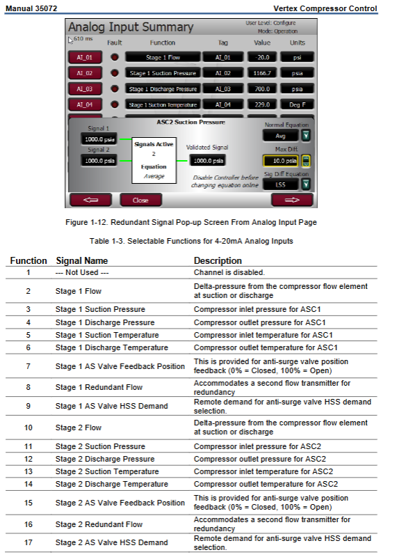
Signal redundancy: Key signals (flow, pressure, temperature) support dual sensor redundancy configuration to enhance reliability.
Technical specifications
(1) Hardware parameters
Category specification details
Processor NXP ARM Cortex-A53 i-MX 8M (quad core 1.6GHz)
Storage 2GB DDR4 RAM+16GB eMMC+1MB FRAM
Display 8.4-inch TFT LCD (800 × 600), 10 point touch, light transmittance ≥ 85%
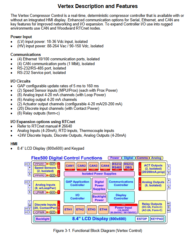
I/O interface AI: 8-way 4-20mA (supports loop power supply); AO: 6-way 4-20mA; actuator output: 2-channel (4-20mA/20-200mA); DI: 20 channels (24Vdc); Relay output: 8-way Form-C
Communication interface Ethernet: 4 RJ45 (10/100M); CAN: 4 (1Mbit); RS-232/485:1 channel; USB service port (disabled)
Extended I/O support for RTCnet nodes (analog I/O, RTD, DI/DO)
(2) Environmental and safety parameters
Category specification details
Working temperature band display: -30~70 ℃; No display: -40~70 ℃
Storage temperature 10~40 ℃ (recommended)
Vibration protection industrial installation: 8.2Grms; Control room: 1.04Grms
Impact protection 10G, 11ms half sine pulse (3 times on each axis)
Protection level: Front IP54 (after installation), shell IP20
Safety certifications ATEX (Zone 2), CSA (Class I, Div 2), IECEx, EMC (EN 61000)
(3) Power parameters
Power type, voltage range, maximum power consumption, isolation level
LV (DC) 18-36Vdc 77W (Vertex)>500Vrms
HV (AC/DC) 88-264Vac/90-150Vdc 73W (AC)/73W (DC)>1500Vrms
Configuration and Operation
Operation mode:
Configuration mode: Configure application parameters (requires Configure permission, compressor shutdown);
Calibration mode: Calibrate output signal (requires Service permission, compressor shutdown);
Operation mode: Normal operation control (Operator and above permissions).
User permissions are divided into four levels: Monitor (read-only), Operator (operation), Service (maintenance), and Configure (configuration). Passwords are distinguished by default (Configure: wg1113).
Configuration process:
Basic configuration: train parameters (units, pressure/temperature range), compressor layout (single/double section);
Core configuration: anti surge map, control parameters (P/I/D), I/O allocation, communication settings;
Verification: Use the Config Check function to check for configuration errors and ensure parameter validity.
Troubleshooting
Hardware malfunction: LED fault code (such as RAM test failure: 2 flashes+1 flash);
Signal failure: supports three fallback strategies: Last Good Value, default value, and intelligent calculation;
Log recording: event log (10ms timestamp), data log (can be exported for analysis).
Maintenance
Maintenance cycle:
Calibration verification: 24-36 months;
Capacitor maintenance: Backup equipment should be powered on for 3 hours every 24-36 months;
RTC battery: has a lifespan of approximately 10 years and cannot be replaced by users (requires authorized service).
- YOKOGAWA
- Reliance
- ADVANCED
- SEW
- ProSoft
- WATLOW
- Kongsberg
- FANUC
- VSD
- DCS
- PLC
- man-machine
- Covid-19
- Energy and Gender
- Energy Access
- Renewable Integration
- Energy Subsidies
- Energy and Water
- Net zero emission
- Energy Security
- Critical Minerals
- A-B
- petroleum
- Mine scale
- Sewage treatment
- cement
- architecture
- Industrial information
- New energy
- Automobile market
- electricity
- Construction site
- HIMA
- ABB
- Rockwell
- Schneider Modicon
- Siemens
- xYCOM
- Yaskawa
- Woodward
- BOSCH Rexroth
- MOOG
- General Electric
- American NI
- Rolls-Royce
- CTI
- Honeywell
- EMERSON
- MAN
- GE
- TRICONEX
- Control Wave
- ALSTOM
- AMAT
- STUDER
- KONGSBERG
- MOTOROLA
- DANAHER MOTION
- Bentley
- Galil
- EATON
- MOLEX
- Triconex
- DEIF
- B&W
- ZYGO
- Aerotech
- DANFOSS
- KOLLMORGEN
- Beijer
- Endress+Hauser
- schneider
- Foxboro
- KB
- REXROTH
- YAMAHA
- Johnson
- Westinghouse
- WAGO
- TOSHIBA
- TEKTRONIX
- BENDER
- BMCM
- SMC
- HITACHI
- HIRSCHMANN
- XP POWER
- Baldor
- Meggitt
- SHINKAWA
- Other Brands
- UniOP
- KUKA
- IBA
- Beckhoff
- ADLINK
-
Beckhoff CX1100-0910 - Power Supply Module
-
Beckhoff C5210-0010 - Communication Module C5210
-
BECKHOFF KL1352 - Bus Terminal SET OF 2 FREE FAST SHIP
-
Beckhoff EL3058 - 8 x analog input single ended 4...20mA 85惟 shunt 12bit
-
Beckoff CX1100-0920 - UPS Module 24VDC (US SELLER) * *
-
BECKHOFF C6920-0000 - C69200000 PLC Moudule
-
Beckhoff CX5120-0115 - CPU controller module CX5120-0115
-
Unknown 15F5C1E-Y50A - Of Frequency Converters
-
Beckhoff AX5118-0000-0200 - Servo Drive HTP0
-
BECKHOFF AX5106-0000-0200 - Servo Drive
-
Beckhoff CX5240-0175 - Module (free) #U2327D YG
-
Beckhoff CP6607-0001-0000 - Compact PC Panel Economy Installation Operator 5,7 "
-
Beckhoff EP3744-0041 - 2022 EP37440041 Module
-
Beckhoff CP6209-0001-0020 - 6.5" PC Touch Screen Control Panel 24VDC
-
Beckhoff CX9020-0111 - /U900 +8x+2xEL3121+1x EL9410+3xEL1008+1x EL2008 Set
-
Beckhoff C6525-1030-0050 - Industrial PC
-
Beckoff CX1100-0920 - UPS Module 24VDC (US SELLER)
-
Beckhoff CX5010-0120 - CX5010 Processor Intel Atom Z510 B24
-
Siemens 6FC5203-0AF04-1BA1 - Operation Panel
-
Beckhoff CX5230-0175 - / 000029724 Embedded PC / Industrial PC on Rail
-
Beckhoff CP3916-0000 - industrielles Anzeige- und Bedienterminal
-
BECKHOFF CX1500-M310 - CX1000-N000 CX1000-0011 CX1000-C00L CX1100-0002 PLC Module
-
Beckhoff EL1872 - 16-channel digital input terminal
-
BECKHOFF EP2318-0001 - module
-
Beckhoff CX9020-0110 - Basic CPU Module
-
Beckhoff EL2564 - EtherCAT Terminal, 4-channel LED output, 5鈥?8VDC, 4A, RGBW
-
Beckhoff CX5130-0155 - /000105637 Automation Embedded PC
-
B&R 400 - Power Control Panel Rev D0 24 VDC
-
Beckhoff CX2020-0155 - module
-
Beckhoff CX9020-0115 - PLC Module
-
BECKHOFF EL6695 - PLC EL 6695
-
BECKHOFF EL7047 - PLC Modules
-
Beckhoff CX1000-0012 - Control HW 2.2 + CX1500-M310 + CX1000-C00L + CX1100-0002+
-
Beckhoff C6920-1039-0030 - control cabinet industrial PC CPU Celeron 1.90 GHz, 2 cores
-
BECKHOFF CX1100-0910 - PLC Module#
-
Beckhoff IL2301-B318-0000 - Coupler Box 4 Channel Digital Input |
-
Beckhoff CX7080 - Module
-
Beckhoff C6930-0060 - Industrial PC
-
Beckhoff CP7902-1060-0000 - Touchscreen 15 " CP7902
-
beckhoff CX9020-0111 - Controller module or UPS
-
Beckhoff CX8091 - PLC Module CX8091
-
Beckhoff C6640-1008-0030 - Control Cabinet Industrial PC
-
BECKHOFF CX1100-0920 - module
-
Beckhoff C9900-M921 - see pictures
-
BECKHOFF CP6829-0001-0000 - Touch Panel
-
BECKHOFF C6930-0060 - Industrial Computer
-
BECKHOFF CX8050 - PLC module
-
Beckhoff CP6202-0021-0020 - Touch Screen #
-
BECKHOFF AM3031-0C20-0000 - SERVO MOTOR
-
Unknown BCH1302N11A1C - Servo motor
-
Beckhoff EL2502 - 2-channel pulse width output terminal
-
Beckhoff EL6731 - Profibus Master / *Rev: 0025
-
Beckhoff CP3918-0010 - Control Panel
-
BECKHOFF CP2915-0010 - [24 MONTH WARRANTY] Control Panel
-
Beckhoff AX5203-0000-0202 - Servo Drive
-
Schneider TSXDSY64T2K - PLC OUTPUT MODULE
-
Beckhoff EP4174-0002 - Module-
-
Beckhoff IL2302-B318-0000 - Profibus Box
-
Beckhoff CP6709-0001-0000 - Touchpanel
-
BECKHOFF CX2030-0123 - Controller
-
Beckhoff CX9020-0111 - Processor Module
-
Beckhoff CX1020-0000 - CX Basic CPU Module
-
Beckhoff AX2003-AS - Servo Drive HTP0
-
Beckhoff C6240-1052-0040 - 4-086-06-3073 Industrial Computer CB1052-0003
-
Beckhoff EL1918 - 8 xTwinSAFE Input
-
Beckhoff AM8072-0R20-0000 - Servomotor
-
BECKHOFF AM8021-1B21-0000 - servo motor #T882 YS
-
Beckhoff EL6224 - 4 X Terminal IO-LINK
-
Beckhoff CX5140-0135 - embedded PC with Intel Atom processor 4 GB HW 3.6
-
Beckhoff CP7201-1000-0000 - Panel PC #
-
Beckhoff CX5130-0121 - Embedded-PC 4GB CPU Module HW 2.5 Industrial PC
-
Beckhoff AM8022-0D41-1002 - Servomotor
-
BECKHOFF CX2030-0130 - Module
-
BECKHOFF EL1872 - 16-channel digital input terminal
-
Unknown GXMMW.A203P33 - 1pc encoder
-
Beckhoff EL6631-0000 - EtherCAT Terminal 2-Port EL 6631
-
BECKHOFF C6925-0030 - Industrial Computer
-
Beckhoff CX8190 - A Module
-
BECKHOFF CX2040-0135 - CX2040-0135/000000927 CPU BASE MODULE i7 2715QE 2.1GHz --
-
BECKHOFF KL6023-0000 - Wireless adapter
-
Saia Burgess PCD7.F700 - PCD7F700 Communication Module
-
Beckhoff CX5130-0112 - CPU Module
-
BECKHOFF CX1020-N010 - CX1020-N000 CX1020-0111 CX1100-0004 EL2008 EL3064 EL4004
-
Beckhoff EP1819-0021 - A Module
-
Beckhoff CX2030-0120 - / 4gb with CX2100 0004
-
B&R X20-XC-0292 - Automation Powerlink Ethernet Bus Controller Module
-
Beckhoff BK3110 - One PLC Module
-
BECKHOFF KL3222 - PLC Module
-
BECKHOFF CX1500-M310 - CX1000-N000 CX1000-0011 CX1000-C00L CX1100-0002 PLC MODULE
-
Beckhoff CP3918-0010 - Control Panel
-
Beckhoff CX2030-0100-1002 - /4GB + CX2100 + CX2550 + CX2500-0060 + SSD
-
Beckhoff EP1816-0008 - PLC Module
-
Beckhoff CX5130-0112 - Module
-
Beckhoff Cx1500-m750 - CPU Hw: 1.4
-
BECKHOFF AX5112-0000-0200 - AX511200000200 Servo Driver
-
Beckhoff EL3751 - EtherCAT Terminal 1 Channel Analog Input Multifunction 24 Bit
-
Beckhoff CX1100-0002 - Power Supply Module
-
Beckhoff CP3916-1016-0010 - Control Panel
-
BECKHOFF CX9001-1101 - #NAME?
-
Beckhoff EP3174-0002 - EtherCAT Box Module
-
Beckhoff C6030-0070 - servo drive
-
Beckhoff CX2020-0120 - /4GB CPU, CX2100-0904, 3x EL6900, EL1904, 16GB Memory
-
BECKHOFF C6110 - BOX-PC 113608
-
BECKHOFF EK1914 - module #P
-
Beckhoff C6140 - Ipox IP-4GVI63 + CH7009A_DVI_TV + SIEMENS A5E00369843 + WD800AAJB
-
Beckhoff CX5020-0111 - controller Good quality
-
BECKHOFF C6015-0010 - / 6559380 ULTRA-COMPACT INDUSTRIAL PC ()
-
Beckhoff AX5203-0000-0200 - PLC module
-
Beckhoff EL2872 - 16-channel digital output terminal
-
BECKHOFF C3640-0000 - Panel Industrial PC 100/240VAC 128MB E0122L
-
Beckhoff CX8031 - Module
-
Beckhoff CX5020-0120-1002 - PLC module#
-
Beckhoff C6140 - M845B + SIEMENS A5E00369843 + C9900_A159_1 + AUTOMATA CAN PCI 1N
-
BECKHOFF AX5112-0000-0200 - Servo Drive*ie
-
B&R ECPA42-01 - Analog Output Module 4-Channel, +/- 10V Output Signal, 20mA Max
-
Beckhoff EL6631-0010 - PLC Module
-
BECKHOFF C6930-0070 - CONTROL CABINET INDUSTRIAL PC
-
BECKHOFF AX5112-0000-0200 - AX511200000200 Servo Driver
-
BECKHOFF EK9000 - Programmable Logic Controller Module EK9000 EK9000
-
BECKHOFF C6920-1028-0000 - Industrial computer
-
Beckhoff CX2030-0120 - controller Module
-
Beckhoff BX8000-0000 - Bus Terminal Controller HW 4.4
-
B&R 3NC154.60-2 - Positioning Module#
-
BECKHOFF CX1020-0122 - PLC module
-
Beckhoff AM3032-0D40-0000 - Servo Motor
-
BECKHOFF CX5020-0111 - CPU Module CX5020-0111
-
Beckhoff CB1051 - G5 Motherboard
-
BECKHOFF KL2641 - 1-channel relay output terminal

K-JIANG

Add: Jimei North Road, Jimei District, Xiamen, Fujian, China
Tell:+86-15305925923