
K-WANG


Westinghouse WGen5500 Generator
Westinghouse WGen5500 Generator
Core specifications of the product
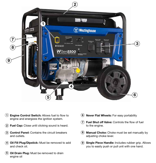
Power and electrical parameters: operating power of 5500 watts, peak power of 6850 watts; Rated voltage 120/240V, frequency 60Hz, total harmonic distortion<23%; The operating current is 23 amperes and the peak current is 28 amperes.
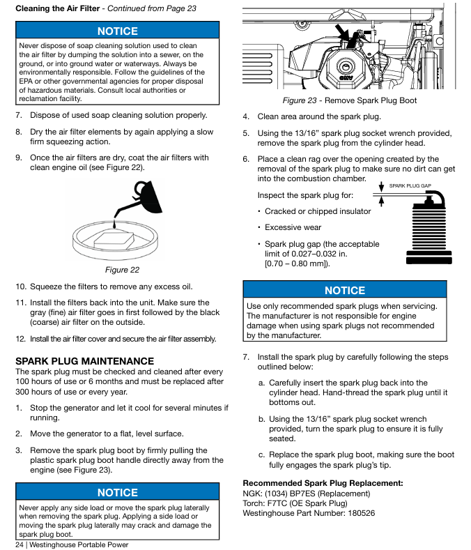
Core configuration: 420cc OHV four stroke engine (13 horsepower), rated speed of 3600RPM; The fuel tank capacity is 25 liters (6.6 gallons), with a range of 20 hours under 1/4 load and 15 hours under 1/2 load; Oil capacity 1.1 liters, recommended SAE 10W30 oil; Spark plug model Torch F7TC, clearance 0.027-0.032 inches (0.70-0.80mm).
Structure and Function: Equipped with one 120/240V 30A twist lock socket (NEMA L14-30R) and two 120V 20A GFCI dual socket sockets (NEMA 5-20R); Including VFT data center (displaying voltage, frequency, and cumulative operating time); Equipped with 10 inch polyurethane wheel and single handle foam grip, easy to move; Net weight 174 pounds (88kg), supports transfer switch connection.
Environment and certification: certified by EPA, CARB, CSA; For every 1000 feet increase in altitude, the power decreases by 3.5%. For altitudes above 5000 feet, a high-altitude carburetor kit (part number 140545) must be installed; Operating noise of 72dBA, equipped with spark arrester.
Safety operation standards (core focus)
1. High risk warning and contraindications
Risk of carbon monoxide poisoning: It is strictly prohibited to use in enclosed/semi enclosed spaces such as indoors, garages, and basements. It can only be operated in outdoor ventilated areas and kept at least 15 feet (4.5 meters) away from doors, windows, ventilation openings, and air conditioning air intakes; Suggest installing a carbon monoxide detector.
Fire and explosion risks: The machine must be stopped and cooled down before refueling; Do not overfill (the oil level should not exceed the neck of the fuel tank filling port); Keep away from sources of fire, sparks (cigarettes, static electricity); When there is a fuel leak, wipe it clean immediately and wait for the area to dry before starting; Do not store fuel indoors during storage.
Electric shock risk: Do not use in damp environments, rainy or snowy weather; Do not touch live terminals and exposed wires during equipment operation; Use grounded three core extension cables and prohibit the use of damaged or aged cables; The connection to the building power grid must be installed by a certified electrician to ensure isolation from the mains power supply.
Other taboos: Not suitable for powering medical equipment; Prohibition of modifying equipment; Overloading operation is prohibited; Do not move or tilt the device while it is running; Prohibit starting with load.
2. General safety requirements
Ensure that there are no obstacles around the equipment during operation and avoid touching high-temperature components such as mufflers and engines (after cooling); Wear protective equipment (gloves, goggles) to avoid direct skin contact with engine oil and gasoline; Wash hands promptly after operation.
Before starting, all loads must be disconnected to avoid damaging the equipment during loaded startup; Grounding must comply with local regulations. If connecting to building systems, an electrician must confirm whether a grounding rod (copper wire ≥ 10 AWG) is required.
Before transportation, the equipment needs to be cooled down and kept level. If necessary, the fuel should be drained; When storing, keep away from sources of fire and heat (such as water heaters, stoves, etc.), and do not use wires or tools to cross the two poles of the battery (if it is an electric starting model).
Assembly and start-up process
1. Open box inspection and assembly
(1) List of unboxing items
Core components: Generator host, wheel assembly (2 pieces), axle pin (2 pieces), washer (2 pieces), M8 × 16mm flange bolt (4 pieces), split pin (2 pieces).
Tools and consumables: spark plug socket wrench, funnel, 1.1L SAE 10W30 engine oil.
Documents: User Manual, Quick Launch Guide, Product Registration Card.
(2) Assembly steps (requiring collaboration between two people to avoid single person handling)
Foot installation: Place the generator on a flat surface and fix the feet on both sides of the frame with M8 flange bolts to ensure a secure installation.
Wheel installation: Insert the axle pin through the washer and wheel into the frame axle bracket, ensuring that the bolt hole faces inward towards the generator; Lock the axle pin hole with an open-ended pin, and repeat the operation on the other side (the wheel is only used for manual movement, dragging or road driving is prohibited).
2. Preparation before startup
Location selection: Outdoor ventilated area, at least 15 feet (4.5 meters) away from buildings and combustibles, on a horizontal and dry surface, avoiding loose materials (sand, grass debris) to prevent blockage of air vents.
Oil inspection:
Engine oil: The new machine has no engine oil and needs to be added to the "MAX" mark on the dipstick (place the cold machine horizontally, wipe the dipstick dry, fully screw it in, and then remove it for inspection).
Fuel: Add unleaded 87-93 gasoline with ethanol content ≤ 10%; Clean the fuel tank after refueling and check for leaks.
Load and grounding: Disconnect all electrical equipment connections; Grounding must comply with local regulations. If connecting to building systems, an electrician must confirm whether a grounding rod is required.
3. Startup and shutdown operations
(1) Start the process
Turn the fuel valve to the "ON" position.
Cold machine: Turn the air damper to "ON"; Heat engine: Set the choke to "OFF".
Push the engine control switch to 'RUN'.
Slowly pull the recoil start rope until the resistance increases, and quickly pull upwards to start (the longest single pull should not exceed 5 seconds, failure should be attempted again with a 10 second interval).
After the engine starts, wait for the RPM to stabilize and gradually retract the choke to "OFF".
Connect electrical equipment (following the principle of "high power first, low power later" to avoid overloading).
(2) Shutdown process
Normal shutdown: Disconnect all loads → Run without load for 3-5 minutes → Turn the engine control switch to "STOP" → Close the fuel valve; Long term non use requires closing the fuel valve and allowing the engine to run until it shuts down on its own (depleting the fuel in the carburetor).
Emergency stop: Simply turn the engine control switch to "STOP" (only used in case of malfunction or danger).
Key maintenance operation details
(1) Oil change
Place the refrigeration unit horizontally, clean the area around the oil discharge port, and place the oil pan.
Remove the oil drain plug, drain the old oil, close the drain plug and tighten it.
Add recommended engine oil to the "MAX" mark on the dipstick through the oil filler port, install the dipstick and filler cap, start the engine and check for leaks.
Waste engine oil should be disposed of according to environmental protection requirements and should not be dumped into sewers, ground or water sources at will.
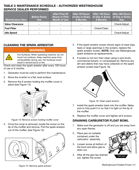
(2) Evacuation of carburetor float (before long-term storage)
Stop the generator for cooling, keep away from sources of fire, and place a container under the carburetor.
Loosen the bottom screw of the carburetor float, drain the remaining fuel, and tighten the screw.
(3) Storage maintenance
Key points for storage duration operation
No special treatment is required within one month, keep the oil and fuel normal, and regularly check the fluid level
Clean the equipment after more than one month → Drain the fuel tank and carburetor float → Change the engine oil → Inject 1 tablespoon of engine oil into the spark plug hole, pull the starting rope to make the piston run (protect the cylinder wall) → Clean the spark arrester → Store in a dry and ventilated place, away from fire sources
Common troubleshooting
Possible causes and solutions for the fault phenomenon
The engine is running but there is no power output. 1. The circuit breaker has tripped; 2. The power cord is not securely plugged in; 3. Power cord/electrical equipment malfunction; 4. GFCI socket tripped; 5. Internal equipment malfunction: 1. Reset the circuit breaker and check for overload; 2. Re plug the plug (the 240V socket needs to be turned clockwise by 1/4 turn); 3. Replace the power cord or test the normal equipment; 4. Press the GFCI reset button; 5. Send to authorized service points
The engine cannot start/stalls after starting. 1. The fuel valve is closed; 2. Lack of fuel/deterioration of fuel; 3. Blockage of oil circuit; 4. The air filter is dirty; 5. Low oil level (low oil protection); 6. Spark plug malfunction/improper clearance; 7. Spark eliminator blockage 1. Open the fuel valve; 2. Add fresh fuel; 3. Clean the oil circuit; 4. Clean/replace the filter; 5. Add engine oil; 6. Adjust/replace spark plugs; 7. Clean the spark eliminator; If it is invalid, send it for repair
Sudden shutdown of generator: 1. Lack of oil; 2. Low oil level (low oil protection); 3. Excessive load 1. Oil replenishment; 2. Add engine oil; 3. Reduce load after restart; If it is invalid, send it for repair
Unstable engine operation/speed fluctuation 1. Air filter blockage; 2. Frequent load switching; 3. Equipment malfunction: 1. Clean the filter; 2. Load fluctuations are a normal phenomenon and do not require any handling; 3. Send to authorized service points
GFCI socket has no power. 1. The socket trips; 2. Socket malfunction: Press the reset button; 2. Send for repair and replacement of sockets
- YOKOGAWA
- Reliance
- ADVANCED
- SEW
- ProSoft
- WATLOW
- Kongsberg
- FANUC
- VSD
- DCS
- PLC
- man-machine
- Covid-19
- Energy and Gender
- Energy Access
- Renewable Integration
- Energy Subsidies
- Energy and Water
- Net zero emission
- Energy Security
- Critical Minerals
- A-B
- petroleum
- Mine scale
- Sewage treatment
- cement
- architecture
- Industrial information
- New energy
- Automobile market
- electricity
- Construction site
- HIMA
- ABB
- Rockwell
- Schneider Modicon
- Siemens
- xYCOM
- Yaskawa
- Woodward
- BOSCH Rexroth
- MOOG
- General Electric
- American NI
- Rolls-Royce
- CTI
- Honeywell
- EMERSON
- MAN
- GE
- TRICONEX
- Control Wave
- ALSTOM
- AMAT
- STUDER
- KONGSBERG
- MOTOROLA
- DANAHER MOTION
- Bentley
- Galil
- EATON
- MOLEX
- Triconex
- DEIF
- B&W
- ZYGO
- Aerotech
- DANFOSS
- KOLLMORGEN
- Beijer
- Endress+Hauser
- schneider
- Foxboro
- KB
- REXROTH
- YAMAHA
- Johnson
- Westinghouse
- WAGO
- TOSHIBA
- TEKTRONIX
- BENDER
- BMCM
- SMC
- HITACHI
- HIRSCHMANN
- XP POWER
- Baldor
- Meggitt
- SHINKAWA
- Other Brands
- UniOP
- KUKA
- IBA
- Beckhoff
-
ADLINK PCI-8134 - 51-12403-0B20 PCB Board Motion Controller Card
-
ADLINK LPCI-3488A - PCI Card 51-12801-0A30 Low Profile IEEE-488 GPIB Card
-
ADLINK NUPRO-900A - industrial computer motherboard Single Board Computer
-
ADLINK cPCI-6840V - industrial control motherboard CompactPCI SBC
-
ADLINK M-342 - industrial motherboard ATX Mainboard
-
ADLINK NUPRO-935A/LV - industrial control motherboard
-
ADLINK cPCI-3538 - CompactPCI Async Serial Communications Module
-
ADLINK PCI-1610 - Card 4-Port RS-232 PCI Serial Communication Card
-
ADLINK HSL-DI32-DB-N - Distributed I/O Module 32-CH Digital Input
-
ADLINK CPCI-6860A - motherboard E7501 CompactPCI Single Board Computer
-
ADLINK PCI-8134A - 4-Axis Motion Control Card PCB Board
-
ADLINK EURESYS LINK - grabbers Video Capture Card Frame Grabber
-
ADLINK NuPRO-965DV - motherboard Industrial Control Board
-
Thermo Fisher Scientific 80100-60500 - 80000-61010R 80000-21000R 80000-60457 Spectrum System Controller ADLINK Components
-
ADLINK PCI-7296 - IO card High Density 96-CH Opto-Isolated DIO Card
-
ADLINK MXC-6322D - Matrix Industrial Computer Fanless Embedded PC
-
ADLINK DIN-825-GP4 - connector board Terminal Block Interface
-
ADLINK AMP-208C - Motion Control Card DSP-based 8-axis
-
ADLINK PCIe-GIE72 - 51-18531-0A10 2-CH GigE Vision Frame Grabber PoE+ Card
-
ADLINK PXIS-3320 - PXI/PXIe Chassis 15-slot 6U PXI/CompactPCI SEM-I-1518=9N41
-
ADLINK MI-965 - Industrial CPU Motherboard
-
ADLINK M-302 - Industrial control motherboard
-
ADLINK PCI-6308V - 51-12202-0A50 Isolated Analog Output Card PCB-I-E-1813=ZA03
-
ADLINK NUPRO-935A - Industrial Mother Board CPU Board
-
ADLINK PCI-7434 - PLOTECH Digital Output Card PCB-I-E-1182=6EX2
-
ADLINK PCI-7432 - 64 Channel Isolated Digital I/O PCI CARD
-
ADLINK NUPRO-935A/DV - 51-41802-0A10 motherboard Industrial Control Board
-
ADLINK PCIe-GIE72 - 51-18531-0A10 2-CH GigE Vision Frame Grabber PoE+ Card
-
ADLINK HSL-DI16DO16-M-NN - HSL-DI16DO16-M-NN(G)-0280 Discrete I/O Module Distributed I/O
-
ADLINK cPCI-6760D / cPCI-6840V - cPCI Single Board Computer Industrial Motherboard
-
ADLINK NuPRO-A301 - Motherboard IPC Motherboard
-
ADLINK NuPRO-935A/LV - motherboard Industrial Control Board
-
ADLINK NUPRO-E320LV - motherboard Industrial Control Board
-
ADLINK NuPRO-E42 - Industrial Control Board Motherboard
-
ADLINK M-342 - ATX Motherboard Industrial PC Mainboard
-
ADLINK CPCI-6860 / 6860A - Industrial Control Motherboard CompactPCI SBC
-
ADLINK AmITX-SL-G-Q170/GEHC(EA)-021E - 51-7A104-0A20 Industrial Motherboard w/ DDR4
-
ADLINK NUPRO-852 / NUPRO-852LV - industrial control motherboard
-
ADLINK DAQ-2006-004 - Multi-Function DAQ Cards Data Acquisition
-
ADLINK PCIe-RTV24 - Frame Grabbers Video Capture Cards PCI-e x1 4-CH 120fps
-
ADLINK PCI-8134 - 51-12403-0B20 4-Axis Motion Controller Card
-
ADLINK PCI-8132 - 2-Axis Motion Controller Card
-
ADLINK cBP-6402 - Backplane Passive Backplane
-
ADLINK cPCI-6760D - cPCI Single Board Computer Industrial Control Motherboard
-
ADLINK DIN-825-4PO(G)-0030 - Terminal Board Motion Control Breakout Board
-
ADLINK M-322 - Industrial Motherboard
-
ADLINK ABX-1301 - 51-63808-0A20 Industrial Motherboard
-
ADLINK PCI-7433 - 64-CH Isolated Digital Input Card
-
ADLINK AMP-208C - Motion Control card
-
ADLINK DIN-50S-01 - TECHNOLOGY TERMINAL BLOCK INTERFACE MODULES W/ DIN RAIL
-
ADLINK PCI-8134 - 51-12403-0B20 4-Axis Motion Controller Card
-
ADLINK MXE-201/MSSD64G - Technology Automation Computer Fanless Embedded System
-
ADLINK USB-3488A (G) - USB to GPIB CARD Controller Interface
-
ADLINK cPCI-3720L2 - SBC Single Board Computer PCB AMAT 0190-14599
-
ADLINK PCI-7251 - Relay Output Board Expansion Module
-
ADLINK PCI-8124-C - PCB Board 4-CH Encoder Trigger Card
-
ADLINK HD636 - Industrial Computer Board PCB-I-E-2200=9L32-2 Main Board
-
ADLINK USB-3488A - THERMOTRON INDUSTRIES IEEE 488 CPU INTERFACE WITH USB/GPIB
-
ADLINK MI-965 - motherboard Industrial CPU Board
-
ADLINK LPCIe-7250 - Technology Digital IO card Low Profile PCIe Relay Output
-
ADLINK NuPro-720/SCOPUS - Technology With 256MB Industrial MotherBoard
-
ADLINK NuPR0-840 - industrial control motherboard
-
ADLINK M-342 - Motherboard ATX PC Mainboard
-
ADLINK MI-965 - motherboard Industrial CPU Board
-
ADLINK CPCI-6530V/4402E/M4G - AMAT CPCI-6503VED/4402E/M4-0/SD64G-2550 Universal SBC
-
ADLINK IMB-M43-IRV - Industrial Motherboard ATX PC Board
-
ADLINK 52983 / 58183 - Chroma PXI I/O Input/Output Card + Carrier Adapter
-
ADLINK PXI-3920 - PXI 3U cPCI Industrial Controller w/ RAM SSD Embedded CPU
-
ADLINK NuPRO-842LV/P - motherboard Industrial Control PC Board
-
ADLINK PCI-7442 - 64-Channel Datalogging Acquisition Switch Card
-
ADLINK PCIe-RTV24 - Cadre Agrippeurs Vidéo de Capture Cartes Pci-E x1 4-CH
-
ADLINK ACL-7122A - TECHNOLOGY 51-11004-1A1 CIRCUIT BOARD 96-CH DIO Card
-
ADLINK PCIe-RTV24 - 51-18016-0A20 Image Acquisition Video Capture Card
-
ADLINK AMP-204C - DSP-Based 4-Axis Advanced Pulse-Train Motion Controller
-
ADLINK 52981 / 58183 - Chroma PXI Digital I/O DIO Input/Output Card + Carrier Adapter
-
ADLINK PCI-8102 - motion control card 2-Axis
-
ADLINK NuPRO-E320LV - industrial computer motherboard
-
ADLINK PCI-RTV24 - card Analog Video Capture Frame Grabber
-
ADLINK M-302 - Motherboard P/N: 08GSAQ96501102
-
ADLINK NEON-1020 - Smart camera Industrial Machine Vision
-
ADLINK AMP- 208C - card DSP-based 8-axis Motion Controller
-
ADLINK PCI-9114DG - Multi-Function Daq Card Data Acquisition
-
ADLINK MXC-6322D/BE_FanG) - Matrix PM2-MXC Fanless Embedded Computer
-
ADLINK DIN-825-4P0 - Terminal Board Motion Control Breakout Board
-
ADLINK HPCI-8S4 REV.B2 - Industrial Control Base Plate Passive Backplane
-
ADLINK HSL-DI32-DB-N - Distributed I/O Module 32-CH Digital Input
-
ADLINK NuPRO-935A/DV - industrial control motherboard
-
ADLINK PCI-7442 - Switch card 64-CH Datalogging Acquisition Card
-
ADLINK NuPRO-E42 - motherboard 51-41808-0A30 Industrial Motherboard
-
ADLINK CPCI-3610D/N45/M1G(G)-10B0 - CompactPCI Intel Atom Single Board Computer CPU Board
-
ADLINK LPCI-7250 - GP Output Isolated Digital Input Card PCB 51-12803-0A10
-
ADLINK PCI-7250 - 51-12007-0A40 PCI7250 8-CH Relay Output & 8-CH Isolated DI Card
-
ADLINK STC-1005 - 10.4inch touch panel PC E3845 CPU
-
ADLINK PCI-FIW64 - image card FireWire Frame Grabber
-
ADLINK NuPRO-935A/LV - industrial computer motherboard
-
ADLINK PCI-8164 00B0 - Centralized Motion Controller 4-axis PCB-I-E-1179=6EX2
-
ADLINK ACLD-9137F REV A1 - 51-14006-101 Screw Termination Board
-
ADLINK PCI-7248 - 51-12006-0A40 Control Card Digital I/O
-
ADLINK HPCI-8S4 - Technology Backplane PCB GaSonics 3500 Asher Passive Backplane
-
ADLINK NuPRO-E320LV - Cpu Board 51-41804-0A20 Industrial Motherboard
-
ADLINK HPX-13S4 - device baseboard Passive Backplane
-
ADLINK M-322 - industrial motherboard
-
ADLINK NuPRO-865 REV :3.0 - industrial motherboard
-
ADLINK DIN-68S-01 - Terminal Block Interface Module Cable Connection
-
ADLINK ETX-IM266-C100Z - motherboard ETX CPU Module
-
ADLINK NuPRO-E320LV - motherboard Industrial Control Board
-
ADLINK NuPRO-841 REV:2.0 - motherboard Industrial PC Board
-
ADLINK ETX-AT-N270-18 - N270 Board ASH-EAT-18/S512 ET Mainboard
-
ADLINK PCI-RTV24 - Image capture card Analog Frame Grabber
-
ADLINK PCI-8102 - card 2-Axis Motion Controller
-
ADLINK M-322 - industrial motherboard
-
ADLINK PCI-9114 REV.C2 - acquisition card Multi-Function DAQ
-
ADLINK NuPRO-865 REV :3.0 - industrial motherboard
-
ADLINK DIN-68S-01 - Terminal Block Interface Module Cable Connection
-
ADLINK M-322 - Industrial Motherboard Mainboard
-
ADLINK CPCI-6860A - E7501 dual Xeon CPCI Single Board Computer
-
ADLINK MXC-6301D(G) - Technology Expandable Fanless Embedded Computer i7-3610E
-
ADLINK NuPRO-842LV - 51-41360-0B1 Industrial Motherboard
-
ADLINK PBP-08A7 R1MO - PCB Industrial Computer Backplane Passive Backplane
-
ADLINK PCI-3488 - PCI BOARD IEEE-488 GPIB Controller Card
-
ADLINK NuPRO-935A/LV - Industrial Control Motherboard
-
ADLINK PCI-8134 - TECH 4-AXIS MOTION CONTROLLER 4209NB2039 AT23A
-
ADLINK Karbon 700-X2 - Expanded High-Performance Rugged Edge Computer Windows 10
-
ADLINK PCIe-9852 - ADcard 2-CH 8-Bit 200MS/s Digitizer Card
-
ADLINK ETX-BT-E3815 - Industrial Control Module NO AUDIO 91-71116-E020 CT66
-
ADLINK cPCI-8168-006 - cPCI NulPC Motion Control Board
-
ADLINK NuPRO-E43 - 51-41809-0A30 industrial motherboard
-
ADLINK PCI-8134A - PCB Board Motion Controller Card

K-JIANG

Add: Jimei North Road, Jimei District, Xiamen, Fujian, China
Tell:+86-15305925923