
K-WANG


Westinghouse iGen5000 Digital Inverter Generator
Engine parameters: displacement 224cc, spark plug model 97109-F7RTC, electrode clearance 0.024-0.032 inches (0.60-0.80mm), intake valve clearance 0.0031-0.0047 inches (0.08-0.12mm), exhaust valve clearance 0.0051-0.0067 inches (0.13-0.17mm).
Westinghouse iGen5000 Digital Inverter Generator
Core parameters and configuration of the product
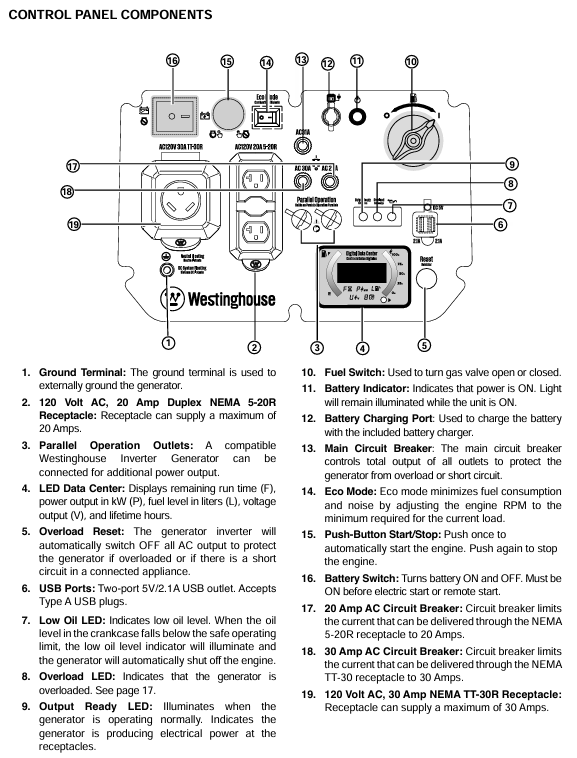
1. Core performance parameters
Power specifications: Operating power of 3900 watts, peak power of 5000 watts, rated voltage of 120V, rated frequency of 60Hz, total harmonic distortion ≤ 3%, single-phase output.
Engine parameters: displacement 224cc, spark plug model 97109-F7RTC, electrode clearance 0.024-0.032 inches (0.60-0.80mm), intake valve clearance 0.0031-0.0047 inches (0.08-0.12mm), exhaust valve clearance 0.0051-0.0067 inches (0.13-0.17mm).
Fuel and engine oil: Tank capacity 3.4 gallons (12.8 liters), recommended 87-93 octane gasoline, ethanol content ≤ 10% (E15/E85 prohibited); The oil capacity is 0.63 US quarts (0.60 liters), and the recommended model for regular use is 10W-30. For extreme temperatures, 5W-30, 10W-40, or 5W-30 synthetic oil can be selected.
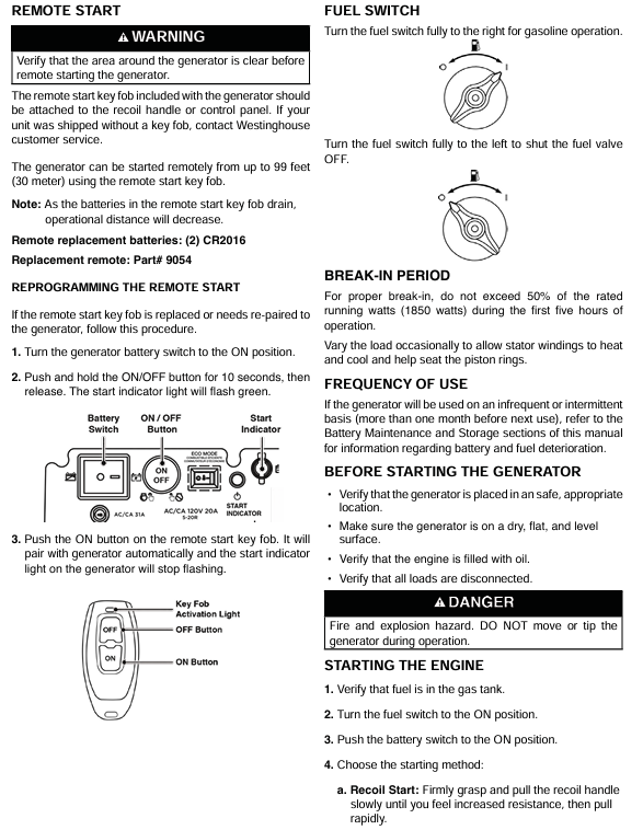
Start and Control: Supports recoil start, electric start, remote start (up to 99 feet/30 meters), equipped with a digital data center that can display remaining operating time, power output, fuel level, voltage, and cumulative operating hours.
2. Key configurations
Control panel: including 120V 20A dual socket (NEMA 5-20R), 120V 30A socket (NEMA TT-30R), USB dual port (5V/2.1A), parallel operation interface, overload reset button, ECO mode switch, etc.
Safety configuration: low oil level indicator light, overload indicator light, output ready indicator light, main circuit breaker and branch circuit breaker, floating neutral grounding system, spark plug lightning arrester.
Portable design: equipped with a retractable handle, transport wheels, and a two person carrying handle, making it easy to move and transport.
Safety operation standards (top priority)
1. Environment and scene security
Only operate in well ventilated outdoor areas, away from closed or semi closed spaces such as doors, windows, ventilation openings, garages, basements, etc., to prevent carbon monoxide poisoning.
Maintain a ventilation gap of at least 5 feet (1.5 meters) around the generator, avoid flammable and combustible materials, and cool for at least 30 minutes after operation before storage or transportation.
Do not use in damp environments (rainy, snowy, or waterlogged), avoid skin contact with engine oil and gasoline, and wear protective equipment during operation.
2. Fuel safety operation
Before refueling, the engine must be turned off and cooled for at least 5 minutes. Smoking or being close to sources of ignition is prohibited to avoid fuel spillage.
Fuel should be stored in approved containers, in a well ventilated area, away from heat and ignition sources, and gasoline should not be used as a cleaning agent.
If there is a fuel leak, it should be wiped clean immediately, and the generator should be started only after the leak area is completely dry. Burning the leaked fuel is prohibited.
3. Electrical safety
It is prohibited to directly connect to the building's power grid unless the conversion switch is installed by a qualified electrician and complies with local electrical regulations.
Only use grounded three core extension cords, tools, and appliances, or double insulated equipment to avoid using worn or damaged wires.
When starting and shutting down the generator, it is necessary to disconnect all load connections and gradually add loads to avoid instantaneous overload.
4. Operation taboos
Not suitable for driving medical support equipment, operation is prohibited when fatigued, under the influence of alcohol, or under the influence of drugs.
During transportation or maintenance, it is necessary to disconnect the spark plug wire and battery connection to prevent accidental starting.
Avoid tilting or flipping the generator to prevent fuel or oil leakage.
Complete operational process
1. Preparation before startup
Check that the generator is placed in a horizontal, dry, and ventilated outdoor area, away from doors, windows, and flammable materials.
Confirm that the oil level is between the L (low) and H (high) marks on the dipstick. If it is insufficient, add the recommended model of oil (new engines do not have oil and need to be refilled for the first time).
Check that the fuel is sufficient, the fuel switch is in the off position, all loads have been disconnected, and the battery switch is in the off state.
Connect battery: Open the battery access cover, ensure the battery is securely fixed, connect the quick connector, and reset the battery cover.
2. Startup steps
Turn on the fuel switch (clockwise to the ON position).
Turn on the battery switch (press to the ON position).
Choose the startup method:
Backlash start: Slowly pull the recoil handle until resistance is felt, then quickly pull it.
Electric start: Long press the start/stop button on the control panel for 2 seconds.
Remote start: Long press the ON button on the remote control for 1 second (distance not exceeding 99 feet).
Maintenance Plan and Operation
1. Battery maintenance
After running for 30-60 minutes, the generator will automatically charge the battery. If not in use for a long time, the accompanying charger should be used to charge for 8 hours per month (no more than 8 hours to avoid overcharging).
Battery replacement: Disconnect the battery and connect the new battery (part number 511019) to the positive and negative poles (red+, white -). Secure the battery strap and reset the battery cover. Dispose of used batteries according to local regulations.
2. Storage maintenance
(1) Short term storage (<1 month)
Clean the surface of the generator, remove the protective cover of the control panel, store in a dry, ventilated place, away from fire and heat sources.
Keep the battery charged once a month to ensure sufficient power for the next use.
(2) Mid term storage (2-6 months)
Add fresh fuel and fuel stabilizer, run the generator for 5 minutes, and allow the stabilizer to circulate throughout the entire fuel system.
Drain the fuel from the carburetor float chamber to avoid the formation of gum and carbon deposits.
Turn off the battery switch, charge once a month, and cover with a dust cover (plastic cover is prohibited to prevent moisture accumulation).
(3) Long term storage (>6 months)
Drain the fuel from the fuel tank (using a manual fuel pump for extraction, electric fuel pumps are prohibited), and clean the fuel filter.
Drain the fuel from the carburetor float chamber, remove the spark plug, inject 1 teaspoon of engine oil into the cylinder, pull the recoil lever to the piston compression stroke (valve closed), and then install the spark plug (without wiring).
Disconnect the battery, store it separately and charge it regularly. Place the generator in a dry, ventilated, and cool place.
Common troubleshooting
Possible causes and solutions for the fault phenomenon
The engine cannot start due to battery switch OFF, insufficient fuel, or fuel deterioration. Open the battery switch and add fresh fuel. If the fuel deteriorates, empty the fuel tank and clean the fuel system
The air filter is dirty and the low oil level triggers a shutdown for cleaning or replacing the air filter. Add engine oil to the standard level
Wait for 5 minutes until the spark plug is wet (flooded), faulty, or has improper clearance, and then pull the recoil handle to exhaust; Disassemble the spark plug, dry or replace it, and adjust the gap to the specified value
Start the battery with recoil when it runs out of power, or charge it for 8 hours with the included charger
Immediately stop the engine after starting, if there is insufficient fuel, abnormal oil level, or clogged air filter, add fuel, check and adjust the oil level, and clean the air filter
Fuel pollution, low fuel level switch malfunction. Drain the fuel tank and add fresh fuel. If the problem is not resolved, contact customer service
The generator lacks power, the air filter is clogged, the fuel has deteriorated or contaminated. Clean or replace the air filter, empty the old fuel and add fresh fuel
Fuel filter blockage, ignition system malfunction, contact authorized service provider for maintenance
Unstable engine operation/engine shutdown, dirty air filter, generator overload, clean air filter, disconnect partial load, ensure total load does not exceed rated power
Replace or repair faulty equipment due to tool or electrical malfunction, and restart the generator
The overload indicator light of the AC socket without output is on, and the circuit breaker trips to disconnect all loads. Press the overload reset button to reset the circuit breaker and check if the load power exceeds the standard
Output ready light not on, equipment failure. Restart the generator and check if the equipment is normal. If there is still no output, contact customer service
Product registration and after-sales support
After starting, wait for the engine speed to stabilize and the output ready indicator light (green) to light up before connecting the load.
ECO mode on: Only used when there is no heavy load. Press the ECO mode switch, and the engine will adjust its speed according to the load, reducing fuel consumption and noise; When driving large start-up loads such as air conditioning and water pumps, the ECO mode needs to be turned off.
3. Operation and load management
The total power of the load shall not exceed 3900 watts (operating power), and the total starting load shall not exceed 5000 watts (peak power).
Load connection sequence: Start the generator first, connect the maximum load after it stabilizes, and then add other loads in sequence. Connect each load and wait for the generator to stabilize.
Extension cable selection: An outdoor dedicated three core grounding extension cable should be used, and the cable diameter should be selected according to the load current (such as using a 10 gauge cable with a length not exceeding 100 feet for a 20A load).
4. Shutdown steps
Disconnect all connected loads, turn off the electrical switch, and unplug the plug.
Run the generator without load for 3-5 minutes to stabilize the internal temperature.
Press the start/stop button on the control panel for 1 second, or the OFF button on the remote control for 1 second.
Turn off the battery switch (press to OFF position) and turn off the fuel switch (turn counterclockwise to OFF position).
If not used for a long time, the fuel and battery should be disposed of according to storage requirements.
5. Special operation: Parallel operation
Only compatible Westinghouse inverter generators can be connected in parallel, requiring the use of dedicated parallel cables (such as 507PC model).
Operation steps:
Both generators have turned off the fuel switch and ECO mode.
Connect the parallel interface of two generators using parallel cables.
Start one generator first, wait for the output ready light to turn on, and then start another one.
Gradually connect the load, with the total load not exceeding the sum of the power of the two generators.
Attention: Do not enable ECO mode during parallel operation to avoid voltage instability during high load startup.
6. High altitude operations (>2000 feet/762 meters)
High altitude carburetor kit (part number 518913-01) needs to be installed, otherwise it will result in decreased performance and increased fuel consumption.
For every 1000 feet increase in altitude, the power decreases by about 3.5%, and the load needs to be adjusted according to the actual altitude.
Do not use high-altitude kits at low altitudes (<2000 feet) to avoid damaging the engine.

- YOKOGAWA
- Reliance
- ADVANCED
- SEW
- ProSoft
- WATLOW
- Kongsberg
- FANUC
- VSD
- DCS
- PLC
- man-machine
- Covid-19
- Energy and Gender
- Energy Access
- Renewable Integration
- Energy Subsidies
- Energy and Water
- Net zero emission
- Energy Security
- Critical Minerals
- A-B
- petroleum
- Mine scale
- Sewage treatment
- cement
- architecture
- Industrial information
- New energy
- Automobile market
- electricity
- Construction site
- HIMA
- ABB
- Rockwell
- Schneider Modicon
- Siemens
- xYCOM
- Yaskawa
- Woodward
- BOSCH Rexroth
- MOOG
- General Electric
- American NI
- Rolls-Royce
- CTI
- Honeywell
- EMERSON
- MAN
- GE
- TRICONEX
- Control Wave
- ALSTOM
- AMAT
- STUDER
- KONGSBERG
- MOTOROLA
- DANAHER MOTION
- Bentley
- Galil
- EATON
- MOLEX
- Triconex
- DEIF
- B&W
- ZYGO
- Aerotech
- DANFOSS
- KOLLMORGEN
- Beijer
- Endress+Hauser
- schneider
- Foxboro
- KB
- REXROTH
- YAMAHA
- Johnson
- Westinghouse
- WAGO
- TOSHIBA
- TEKTRONIX
- BENDER
- BMCM
- SMC
- HITACHI
- HIRSCHMANN
- XP POWER
- Baldor
- Meggitt
- SHINKAWA
- Other Brands
- UniOP
- KUKA
- IBA
- Beckhoff
-
ADLINK CPCI-6860A - 51-31310-OB10 industrial motherboard CompactPCI SBC
-
ADLINK AmITX-SL-G-H110 - 51-7A104-0A30 Mini-ITX Industrial Motherboard
-
ADLINK PXI-2005-003 - CPCI Industrial PC Data Acquisition Card Multi-Function DAQ
-
ADLINK DININ-814M - 51-14032-0A3D SCSI-100P cable connection Interface Terminal Board
-
ADLINK CPCI-3920NA/C2D15/M1G - 3U CompactPCI Intel Core 2 Duo Single Board Computer
-
ADLINK PCIE-8560 - 51-18014-0A20 Communication Card High Speed DAQ
-
ADLINK PCI-C154+ - Motion Control Card 4-axis Motion Controller Board
-
ADLINK PCI-RTV24 - image capture card Analog Video Frame Grabber
-
ADLINK NuPRO-842LV/P - 51-41360-0B30 Industrial Motherboard CPU Board
-
ADLINK cBP-3208/3208R - CPCI Board 3U 8-Slot CompactPCI Backplane
-
ADLINK PCI-8164 - 4-Axis Motion Controller PCI Card 51-12406-0A40
-
ADLINK PCIe-GIE64+ - 4-CH GigE Vision PoE+ Frame Grabber Video Capture Card
-
ADLINK CPCI-6860 / 6860A - CompactPCI Dual Xeon Single Board Computer
-
ADLINK IEC-915GV - REV 1.1 Industrial motherboard CPU Board
-
ADLINK ND-6520 - Technology RS-232 to RS-422RS-485 Converter NuDAM Module
-
ADLINK RTV-24 / PCI-MP4S - 51-12519-1C30 4-Channel Real Time Video Capture Board
-
ADLINK cPCI-6910 / cPCI-6910AM/M1G - cPCI-6910AM/DXL16/M1G/S80G(G)-3120 BOARD CompactPCI SBC
-
ADLINK NUPRO-A40H - Linghua 51-41807-1A30 Industrial Control Computer Motherboard
-
ADLINK USB-3488A - USB to GPIB INTERFACE USB-3488A(G) Controller Module
-
ADLINK PCI-8134A - motion control card 4-Axis Controller Card
-
ADLINK PCI-8134 - 51-12403-0B20 PCB Board Motion Controller Card
-
ADLINK LPCI-3488A - PCI Card 51-12801-0A30 Low Profile IEEE-488 GPIB Card
-
ADLINK NUPRO-900A - industrial computer motherboard Single Board Computer
-
ADLINK cPCI-6840V - industrial control motherboard CompactPCI SBC
-
ADLINK M-342 - industrial motherboard ATX Mainboard
-
ADLINK NUPRO-935A/LV - industrial control motherboard
-
ADLINK cPCI-3538 - CompactPCI Async Serial Communications Module
-
ADLINK PCI-1610 - Card 4-Port RS-232 PCI Serial Communication Card
-
ADLINK HSL-DI32-DB-N - Distributed I/O Module 32-CH Digital Input
-
ADLINK CPCI-6860A - motherboard E7501 CompactPCI Single Board Computer
-
ADLINK PCI-8134A - 4-Axis Motion Control Card PCB Board
-
ADLINK EURESYS LINK - grabbers Video Capture Card Frame Grabber
-
ADLINK NuPRO-965DV - motherboard Industrial Control Board
-
Thermo Fisher Scientific 80100-60500 - 80000-61010R 80000-21000R 80000-60457 Spectrum System Controller ADLINK Components
-
ADLINK PCI-7296 - IO card High Density 96-CH Opto-Isolated DIO Card
-
ADLINK MXC-6322D - Matrix Industrial Computer Fanless Embedded PC
-
ADLINK DIN-825-GP4 - connector board Terminal Block Interface
-
ADLINK AMP-208C - Motion Control Card DSP-based 8-axis
-
ADLINK PCIe-GIE72 - 51-18531-0A10 2-CH GigE Vision Frame Grabber PoE+ Card
-
ADLINK PXIS-3320 - PXI/PXIe Chassis 15-slot 6U PXI/CompactPCI SEM-I-1518=9N41
-
ADLINK MI-965 - Industrial CPU Motherboard
-
ADLINK M-302 - Industrial control motherboard
-
ADLINK PCI-6308V - 51-12202-0A50 Isolated Analog Output Card PCB-I-E-1813=ZA03
-
ADLINK NUPRO-935A - Industrial Mother Board CPU Board
-
ADLINK PCI-7434 - PLOTECH Digital Output Card PCB-I-E-1182=6EX2
-
ADLINK PCI-7432 - 64 Channel Isolated Digital I/O PCI CARD
-
ADLINK NUPRO-935A/DV - 51-41802-0A10 motherboard Industrial Control Board
-
ADLINK PCIe-GIE72 - 51-18531-0A10 2-CH GigE Vision Frame Grabber PoE+ Card
-
ADLINK HSL-DI16DO16-M-NN - HSL-DI16DO16-M-NN(G)-0280 Discrete I/O Module Distributed I/O
-
ADLINK cPCI-6760D / cPCI-6840V - cPCI Single Board Computer Industrial Motherboard
-
ADLINK NuPRO-A301 - Motherboard IPC Motherboard
-
ADLINK NuPRO-935A/LV - motherboard Industrial Control Board
-
ADLINK NUPRO-E320LV - motherboard Industrial Control Board
-
ADLINK NuPRO-E42 - Industrial Control Board Motherboard
-
ADLINK M-342 - ATX Motherboard Industrial PC Mainboard
-
ADLINK CPCI-6860 / 6860A - Industrial Control Motherboard CompactPCI SBC
-
ADLINK AmITX-SL-G-Q170/GEHC(EA)-021E - 51-7A104-0A20 Industrial Motherboard w/ DDR4
-
ADLINK NUPRO-852 / NUPRO-852LV - industrial control motherboard
-
ADLINK DAQ-2006-004 - Multi-Function DAQ Cards Data Acquisition
-
ADLINK PCIe-RTV24 - Frame Grabbers Video Capture Cards PCI-e x1 4-CH 120fps
-
ADLINK PCI-8134 - 51-12403-0B20 4-Axis Motion Controller Card
-
ADLINK PCI-8132 - 2-Axis Motion Controller Card
-
ADLINK cBP-6402 - Backplane Passive Backplane
-
ADLINK cPCI-6760D - cPCI Single Board Computer Industrial Control Motherboard
-
ADLINK DIN-825-4PO(G)-0030 - Terminal Board Motion Control Breakout Board
-
ADLINK M-322 - Industrial Motherboard
-
ADLINK ABX-1301 - 51-63808-0A20 Industrial Motherboard
-
ADLINK PCI-7433 - 64-CH Isolated Digital Input Card
-
ADLINK AMP-208C - Motion Control card
-
ADLINK DIN-50S-01 - TECHNOLOGY TERMINAL BLOCK INTERFACE MODULES W/ DIN RAIL
-
ADLINK PCI-8134 - 51-12403-0B20 4-Axis Motion Controller Card
-
ADLINK MXE-201/MSSD64G - Technology Automation Computer Fanless Embedded System
-
ADLINK USB-3488A (G) - USB to GPIB CARD Controller Interface
-
ADLINK cPCI-3720L2 - SBC Single Board Computer PCB AMAT 0190-14599
-
ADLINK PCI-7251 - Relay Output Board Expansion Module
-
ADLINK PCI-8124-C - PCB Board 4-CH Encoder Trigger Card
-
ADLINK HD636 - Industrial Computer Board PCB-I-E-2200=9L32-2 Main Board
-
ADLINK USB-3488A - THERMOTRON INDUSTRIES IEEE 488 CPU INTERFACE WITH USB/GPIB
-
ADLINK MI-965 - motherboard Industrial CPU Board
-
ADLINK LPCIe-7250 - Technology Digital IO card Low Profile PCIe Relay Output
-
ADLINK NuPro-720/SCOPUS - Technology With 256MB Industrial MotherBoard
-
ADLINK NuPR0-840 - industrial control motherboard
-
ADLINK M-342 - Motherboard ATX PC Mainboard
-
ADLINK MI-965 - motherboard Industrial CPU Board
-
ADLINK CPCI-6530V/4402E/M4G - AMAT CPCI-6503VED/4402E/M4-0/SD64G-2550 Universal SBC
-
ADLINK IMB-M43-IRV - Industrial Motherboard ATX PC Board
-
ADLINK 52983 / 58183 - Chroma PXI I/O Input/Output Card + Carrier Adapter
-
ADLINK PXI-3920 - PXI 3U cPCI Industrial Controller w/ RAM SSD Embedded CPU
-
ADLINK NuPRO-842LV/P - motherboard Industrial Control PC Board
-
ADLINK PCI-7442 - 64-Channel Datalogging Acquisition Switch Card
-
ADLINK PCIe-RTV24 - Cadre Agrippeurs Vidéo de Capture Cartes Pci-E x1 4-CH
-
ADLINK ACL-7122A - TECHNOLOGY 51-11004-1A1 CIRCUIT BOARD 96-CH DIO Card
-
ADLINK PCIe-RTV24 - 51-18016-0A20 Image Acquisition Video Capture Card
-
ADLINK AMP-204C - DSP-Based 4-Axis Advanced Pulse-Train Motion Controller
-
ADLINK 52981 / 58183 - Chroma PXI Digital I/O DIO Input/Output Card + Carrier Adapter
-
ADLINK PCI-8102 - motion control card 2-Axis
-
ADLINK NuPRO-E320LV - industrial computer motherboard
-
ADLINK PCI-RTV24 - card Analog Video Capture Frame Grabber
-
ADLINK M-302 - Motherboard P/N: 08GSAQ96501102
-
ADLINK NEON-1020 - Smart camera Industrial Machine Vision
-
ADLINK AMP- 208C - card DSP-based 8-axis Motion Controller
-
ADLINK PCI-9114DG - Multi-Function Daq Card Data Acquisition
-
ADLINK MXC-6322D/BE_FanG) - Matrix PM2-MXC Fanless Embedded Computer
-
ADLINK DIN-825-4P0 - Terminal Board Motion Control Breakout Board
-
ADLINK HPCI-8S4 REV.B2 - Industrial Control Base Plate Passive Backplane
-
ADLINK HSL-DI32-DB-N - Distributed I/O Module 32-CH Digital Input
-
ADLINK NuPRO-935A/DV - industrial control motherboard
-
ADLINK PCI-7442 - Switch card 64-CH Datalogging Acquisition Card
-
ADLINK NuPRO-E42 - motherboard 51-41808-0A30 Industrial Motherboard
-
ADLINK CPCI-3610D/N45/M1G(G)-10B0 - CompactPCI Intel Atom Single Board Computer CPU Board
-
ADLINK LPCI-7250 - GP Output Isolated Digital Input Card PCB 51-12803-0A10
-
ADLINK PCI-7250 - 51-12007-0A40 PCI7250 8-CH Relay Output & 8-CH Isolated DI Card
-
ADLINK STC-1005 - 10.4inch touch panel PC E3845 CPU
-
ADLINK PCI-FIW64 - image card FireWire Frame Grabber
-
ADLINK NuPRO-935A/LV - industrial computer motherboard
-
ADLINK PCI-8164 00B0 - Centralized Motion Controller 4-axis PCB-I-E-1179=6EX2
-
ADLINK ACLD-9137F REV A1 - 51-14006-101 Screw Termination Board
-
ADLINK PCI-7248 - 51-12006-0A40 Control Card Digital I/O
-
ADLINK HPCI-8S4 - Technology Backplane PCB GaSonics 3500 Asher Passive Backplane
-
ADLINK NuPRO-E320LV - Cpu Board 51-41804-0A20 Industrial Motherboard
-
ADLINK HPX-13S4 - device baseboard Passive Backplane
-
ADLINK M-322 - industrial motherboard
-
ADLINK NuPRO-865 REV :3.0 - industrial motherboard
-
ADLINK DIN-68S-01 - Terminal Block Interface Module Cable Connection
-
ADLINK ETX-IM266-C100Z - motherboard ETX CPU Module
-
ADLINK NuPRO-E320LV - motherboard Industrial Control Board
-
ADLINK NuPRO-841 REV:2.0 - motherboard Industrial PC Board
-
ADLINK ETX-AT-N270-18 - N270 Board ASH-EAT-18/S512 ET Mainboard

K-JIANG

Add: Jimei North Road, Jimei District, Xiamen, Fujian, China
Tell:+86-15305925923