
K-WANG


YOKOGAWA ZR22G, ZR402G split zirconia oxygen/humidity analyzer
YOKOGAWA ZR22G, ZR402G split zirconia oxygen/humidity analyzer
Core parameters and components of the product
(1) Core components and functions
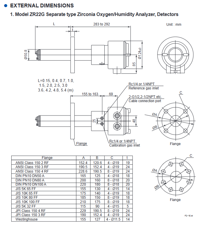
ZR22G detector:
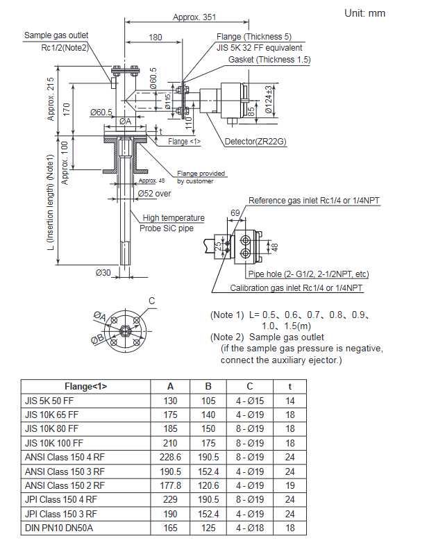
Type: Universal type (sample temperature range 0-700 ℃), High temperature type (0.15m probe, paired with ZO21P adapter, sample temperature range 0-1400 ℃)
Probe length: 0.15-5.4m (excluding 0.15m for humidity analyzer), material: SUS316 (universal type), SiC/SUS310S (high temperature type)
Protection level: equivalent IP44D (universal type), IP66 (pressure compensation type, when cable is sealed)
ZR402G converter:
Display: 320 × 240 dot LCD touch screen, supporting numerical values, trend charts, and fault display
Power supply: 100-240V AC (50/60Hz), maximum power consumption of 300W
Communication: Supports HART protocol (refer to IM 11M12A01-51E document)
Auxiliary equipment:
ZO21R probe protector: suitable for scenarios with gas velocity ≥ 10m/s, anti dust wear
ZH21A dust protector: only for use with humidity analyzers, to prevent combustible dust from entering
ZA8F flow setting unit: for manual calibration, controlling the flow rate of calibration gas/reference gas
ZR40H automatic calibration unit: automatically switches calibration gas, supports timed calibration
(2) Key measurement parameters
Measurement type, measurement range, accuracy, related indicators, response time
Oxygen concentration 0.01-100 vol% O ₂ repeatability ± 0.5% -1% (range), linearity ± 1% -3% (range) 90% response ≤ 5 seconds
Humidity (volume fraction) 0-100 vol% H ₂ O repeatability ± 1 vol% H ₂ O (sample gas pressure ≤ 2kPa)-
Humidity (mixing ratio) 0-1.000 kg/kg --
Core operating procedures
(1) Installation and wiring
Installation requirements:
Environment: Detector ambient temperature -20-150 ℃, converter -20-55 ℃, no corrosive gases, no vibration
Probe installation: For lengths ≤ 2m, it can be installed horizontally to vertically. For lengths ≥ 2.5m, it needs to be installed vertically (± 5 °). High temperature SiC probes need to be installed vertically
Flange specifications: Supports JIS, ANSI, DIN and other standards, and needs to be matched with equipment models
Wiring specifications:
Cable: 6-core shielded cable for detector signal (two-way resistance ≤ 10 Ω), 2-core cable for heater, temperature resistance ≥ 80 ℃
Grounding: Protective grounding resistance ≤ 100 Ω, shielding layer connected to converter FG terminal
Partition wiring: separate signal cables from power/heater cables to avoid interference
(2) Calibration process
Calibration preparation:
Gas requirements: Zero gas (0.95-1.0 vol% O ₂+N ₂), span gas (dry and clean air, dew point ≤ -20 ℃)
Flow setting: Calibrate air flow rate of 600 ± 60 ml/min, reference air flow rate of 800-1000 ml/min
Calibration mode selection:
Manual calibration: Gas valve is manually controlled through ZO21S/ZA8F unit, suitable for system 1/2
Semi automatic calibration: Start with touch panel or touch input, complete calibration according to preset time
Automatic calibration: System 3 dedicated, automatically executed at set intervals (up to 255 days)
Core steps:
Span calibration: Introduce span gas and confirm calibration after the value stabilizes
Zero calibration: Introduce zero gas and complete calibration in the same way
After calibration: Close the calibration gas valve and wait for the output to stabilize (default 10 minutes)
(3) Key points for safe operation
Power safety: Confirm that the power supply voltage matches the rated value of the equipment (100-240V AC), and disconnect the power before wiring
High temperature protection: The working temperature of the detector probe reaches 750 ℃, and gloves should be worn during maintenance to avoid direct contact
Gas safety: Calibration gas/sample gas may be toxic, ventilation or protective mask should be worn during maintenance, and pipelines should be checked for leaks
Sensor protection: The sensor is made of ceramic material to avoid impact and pressure, and direct contact with water droplets is prohibited
Maintenance and troubleshooting
(1) Regular maintenance
Daily maintenance: Clean and calibrate the gas pipeline (anti clogging), check the filter (K9471UA dust filter)
Regular replacement: Sensor components (according to the calibration coefficient, zero gas calibration proportional to 100 ± 30% and span gas calibration proportional to 0 ± 18% are normal), metal O-rings (must be replaced when replacing sensors), heater units (when resistance is abnormal)
Cycle: It is recommended to conduct regular inspections at intervals not exceeding those specified in the equipment manual, and the calibration cycle should be adjusted according to the usage scenario
(2) Common faults and their solutions
Key points for troubleshooting fault types, fault codes/phenomena
Cell voltage fault Error 1: Check the CELL ± wiring, whether the sensor is damaged, and the internal wiring of the detector
Heater temperature fault Error 2: Check the heater resistance (≤ 90 Ω), thermocouple wiring, and cold end temperature (-25-155 ℃)
Zero calibration coefficient alarm Alarm 6 confirms that the zero gas concentration is consistent with the set value, the gas flow rate is normal, and the sensor is not contaminated
High measurement value (oxygen analyzer) - check whether the reference gas humidity is stable, whether the calibration gas leaks, and whether the sample gas pressure is abnormal
Other key information
Product disposal: Local/national environmental regulations must be followed, and batteries must be classified and recycled (EU/UK region)
Spare parts list: Key spare parts include sensor components (E7042UD/ZR01A01), fuses (A1113EF, 3.15A), and metal O-rings (K9470BJ)
Key issues
Question 1: What are the core differences between the three system configurations of ZR22G and ZR402G analyzers? What scenarios are they applicable to?
Answer: The core difference lies in the calibration method and auxiliary equipment configuration, which are applicable in the following scenarios:
System 1: Only includes detector+converter+ZO21S standard gas unit, without fixed calibration gas pipeline, requiring manual connection of calibration gas, suitable for simple humidity monitoring scenarios such as small boiler oxygen concentration monitoring and food production;
System 2: Add ZA8F flow setting unit, zero gas cylinder, pressure reducing valve, reference gas is instrument air, support manual precise calibration, suitable for scenarios such as large boilers and heating furnaces that require regular manual calibration;
System 3: Replace with ZR40H automatic calibration unit, support timed automatic calibration, including combustible gas detection contact input (cutting off heater power), suitable for scenarios such as large industrial furnaces that require long-term stable operation and reduce manual intervention.
Question 2: How to determine if the sensor (zirconia cell) needs to be replaced? What are the key points to pay attention to when replacing?
answer:
Replacement criteria: ① The calibrated zero gas calibration ratio exceeds 100 ± 30% or the span gas calibration ratio exceeds 0 ± 18%; ② In the detailed data display, the cell internal resistance significantly increased (new sensor ≤ 200 Ω, reaching 3-10k Ω after aging); ③ Cell robustness shows' life<1 month '; ④ The sensor has cracks, corrosion, or impact damage.
Replacement precautions: ① Operate after the detector has completely cooled down to avoid high-temperature burns; ② The metal O-ring (K9470BJ) and contact (E7042BS) must be replaced and old parts cannot be reused; ③ When installing the sensor, the four fixing bolts should be tightened evenly (with a torque of about 5.9 N · m) to avoid uneven force damage; ④ After replacement, the calibration process needs to be re executed to ensure measurement accuracy.
Question 3: What is the highest priority troubleshooting step when the device displays Error 2 (heater temperature fault)? What are the corresponding criteria for judgment?
Answer: The steps and criteria for priority screening are as follows:
Firstly, check the polarity of the thermocouple wiring: confirm that the detector TC+is connected to the converter TC+, and TC - is connected to TC -. If connected incorrectly, it will directly cause abnormal temperature detection, which is the most common cause;
Measure heater resistance: Disconnect the HTR terminal of the detector and measure the resistance value. The normal value should be ≤ 90 Ω. If the resistance value is too high, the heater will be disconnected and the heater unit needs to be replaced;
Check thermocouple resistance: After the detector cools down to a temperature difference of ≤ 50 ℃ from the environment, measure the TC ± terminal resistance. Normally, it should be ≤ 5 Ω. If it is>5 Ω, the thermocouple will break and the heater unit needs to be replaced;
Check the cold end temperature: Check the C.J. temperature through detailed data display. The normal temperature should be between -25-155 ℃. If it exceeds, check the cold end sensor or wiring.
- YOKOGAWA
- Reliance
- ADVANCED
- SEW
- ProSoft
- WATLOW
- Kongsberg
- FANUC
- VSD
- DCS
- PLC
- man-machine
- Covid-19
- Energy and Gender
- Energy Access
- Renewable Integration
- Energy Subsidies
- Energy and Water
- Net zero emission
- Energy Security
- Critical Minerals
- A-B
- petroleum
- Mine scale
- Sewage treatment
- cement
- architecture
- Industrial information
- New energy
- Automobile market
- electricity
- Construction site
- HIMA
- ABB
- Rockwell
- Schneider Modicon
- Siemens
- xYCOM
- Yaskawa
- Woodward
- BOSCH Rexroth
- MOOG
- General Electric
- American NI
- Rolls-Royce
- CTI
- Honeywell
- EMERSON
- MAN
- GE
- TRICONEX
- Control Wave
- ALSTOM
- AMAT
- STUDER
- KONGSBERG
- MOTOROLA
- DANAHER MOTION
- Bentley
- Galil
- EATON
- MOLEX
- Triconex
- DEIF
- B&W
- ZYGO
- Aerotech
- DANFOSS
- KOLLMORGEN
- Beijer
- Endress+Hauser
- schneider
- Foxboro
- KB
- REXROTH
- YAMAHA
- Johnson
- Westinghouse
- WAGO
- TOSHIBA
- TEKTRONIX
- BENDER
- BMCM
- SMC
- HITACHI
- HIRSCHMANN
- XP POWER
- Baldor
- Meggitt
- SHINKAWA
- Other Brands
- UniOP
- KUKA
- IBA
- Beckhoff
-
ADLINK PCI-7433 - switch value acquisition card Isolated Digital Input Card
-
ADLINK PCI-9112 - 51-12252-0D20 Multi-Function Data Acquisition Card
-
ADLINK NUPRO-A301 REV:1.4 - industrial control motherboard PICMG Full-Size SBC
-
ADLINK 51-18502-0A10 - Frame Grabber Image Acquisition Interface Card
-
ADLINK PCI-7296 - 51-12009-0A50 PCB-I-E-925=6DX1 96-CH Parallel Digital I/O Board
-
ADLINK PCI-8132 GP A2 - Motion Control Card 2-Axis Servo & Stepper Controller
-
ADLINK PCI-7442 - switch quantity card data acquisition card 64-CH Isolated Card
-
ADLINK HPX-13S4 - baseboard PICMG 1.3 Passive Backplane Chassis Baseplate
-
ADLINK NuPRO-590 / NTC-567-ZM-F36 - Single Board Computer PCB-I-E-1853=9L21 Half-Size SBC
-
ADLINK PCIe-8332 - 16-axis plate Motion Control Hardware Card
-
ADLINK NuPRO-775 REV.B1 - motherboard Pentium 4 Full-Size PICMG SBC
-
ADLINK PXI-3920 - Embedded Controller 3U PXI cPCI System Intelligence Board
-
ADLINK PCI-8134 - driver card motion control card 4-Axis Controller Board
-
ADLINK HSL-DI32-M-N-011 / HSL-TB32-M-DIN - Digital Input & Base Module PLC Distributed I/O System
-
ADLINK PCI-6216V-206 / PCI-208V 009 - 16 CH 16bit analog output card
-
ADLINK NuPro-E330 - 51-41805-0A20 PCB Single Board Computer Host Board
-
ADLINK PCI-1622C - Card 8-Port RS-232/422/485 PCI Serial Communication Board
-
ADLINK PCIe-7432 - 51-18402-0A10 Carte PCIe Avec Plage D'Entrée Élevée Isolated DIO Card
-
ADLINK PCI-7250 - PCI Acquisition Card 8-CH Relay Output Isolated DI Card
-
ADLINK PCI-7230 - 32-CH Isolated Digital I/O Card
-
ADLINK PCI-8164 - PCB 4-Axis Motion Controller Card
-
ADLINK PCI-7854 - Collection card High-Speed Link Distributed Motion Controller
-
ADLINK NuPRO-935A/LV - industrial control computer motherboard Full-Size PICMG SBC
-
ADLINK IMB-M40H - motherboard IH61-AA4 1155 LGA1155 Micro-ATX Mainboard
-
ADLINK PCI-7248 - Linhua 51-12006-0A40 48-CH Parallel Digital I/O Card
-
ADLINK HPCI-14S12U - Linhua industrial computer baseboard Passive Backplane
-
ADLINK PCI-8132 Rev.A2 - 2-Axis Servo & Stepper Motion Controller Card
-
ADLINK ACL-8111 - ISA card Multi-Function DAQ Card
-
ADLINK ACL-8111 - ISA card Multi-Function Data Acquisition Board
-
ADLINK PCI-7200 REV.A3 - Digital I/O card 12MB/s High-Speed Parallel Digital I/O
-
ADLINK PCI-7296 REV.A3 - 96-CH High-Density Opto-Isolated DIO Card
-
ADLINK PCI-7434 - 64-CH Isolated Digital Output Card
-
ADLINK M-342 - atx motherboard Industrial PC Mainboard
-
ADLINK NuPRO-935ADV (A) 1.9 - CPU Board Intel Core 2 Quad CPU Q9500 2.83GHz PICMG Board
-
ADLINK NUPRO-935A/DV - motherboard dual network port 51-41802-0A10 CPU Board
-
ADLINK PCI-RTV24 - image capture card Analog Video Frame Grabber Board
-
ADLINK HPX-13S4 - device baseboard PICMG 1.3 Passive Backplane Chassis Baseplate
-
ADLINK PCI-8134A - control card 4-Axis Motion Controller Card
-
ADLINK ACL-7130 REV. B2 - industrial control capture card Isolated Digital I/O Board
-
ADLINK EBP-13E2 - Industrial Backplane Board Passive Backplane Baseboard
-
ADLINK NuPRO-935ADV (A) 1.9 - CPU Board Intel Core 2 Quad CPU Q9500 2.83GHz PICMG SBC
-
ADLINK PCI-8134A - motion control card 4-Axis Pulse-Train Controller Card
-
ADLINK PCI-9112 REV A.1 - Multi Function DA&C Board Data Acquisition Card
-
ADLINK 51-12001-0C20 - Circuit Board Multi-Function Data Acquisition Hardware
-
ADLINK PCI-7300A - 80-CH High-Speed Digital I/O Card
-
ADLINK PCI-7230 - 16-CH Isolated Digital Input Output Card
-
ADLINK DIN-814-GP - motion control module Interface Terminal Block
-
ADLINK NUPRO-A40H - 51-41807-1A20 Industrial Control Motherboard LGA1155
-
ADLINK PCI-7433 rev A2 - Isolated Digital Input Card
-
ADLINK NuPRO-780 - Pentium III 800 512 MB SBC NuPRO780 51-41309-0B2 Single Board Computer
-
ADLINK PCI-7853 / PCI-7854 - Acquisition card High-Speed Link Control Card
-
ADLINK NUPRO-852 / NUPRO-852LV - Industrial motherboard Full-Size PICMG CPU Board
-
ADLINK NuPRO-842LV/P - 51-41360-0B30 Industrial Motherboard Half-Size PICMG SBC
-
ADLINK PCI-FIW64 - 4/2 Channel IEEE1394B Image Capture Card Frame Grabber
-
ADLINK PCI-7851 Rev A1.1 - HSL system card High-Speed Link Master Controller
-
ADLINK PCI-7230 - 51-12003-0A50 card 32-CH Isolated Digital I/O Card
-
ADLINK NuPRO-841REV:1.0 - Industrial CPU Board Mainboard
-
ADLINK NuPRO-841 REV:1.0 - motherboard Industrial Control PC Mainboard
-
ADLINK PCI-8256 - 8-Axis Advanced Motion Control PCI Board
-
ADLINK PCI-6S / PCI6S - Backplane 6-Slot Passive Backplane Board
-
ADLINK PCI-7234 REV B3 - 32-CH Isolated Digital Output PCI Card
-
ADLINK PCI-8213 - HannStar MV-4 51-45003-0b4 Board
-
ADLINK PCI-7233 - 51-12004-0a20 board PCI7233 32-CH Isolated Digital Input Card
-
ADLINK PCI-7851 - 006 51-24003-0B20 High-Speed Link Master Motion Control Card
-
ADLINK PCI-7432 - 64-CH Isolated Digital I/O PCI Cards
-
ADLINK LPCI-3488 - Card Low Profile IEEE-488 GPIB Interface Card
-
ADLINK HPCI14S REV.B1 - industrial control computer base plate Passive Backplane
-
ADLINK NEON-1020 - Industrial camera Smart Camera Vision System
-
ADLINK PCI-7432 - Isolated Digital I/O PCI Card 64-CH
-
ADLINK Pcm-7250+ - 8-Ch Relay Outputs & 8-Ch Isolated DI Module PC/104
-
ADLINK CPCI-7841 - DUAL-PORT ISOLATED CAN INTERFACE CARD CompactPCI
-
ADLINK PCI-3488 / PCI-GPIB - PCI IEEE-488 GPIB Interface Card
-
ADLINK PCI-1711U - Card Multi-Function Data Acquisition Board
-
ADLINK NUPRO-A301 - REV:1.1 1.2 1.4 PICMG Full-Size Single Board Computer
-
Adlink DIN-50S-01 - PLOTECH 51-14024-0A40 50-pin Wiring Terminal Board
-
Chroma 52962 / 58183 - PXI Optical Spectrometer carrier adapter Card
-
ADLINK PCI-6208V - PCI DATA ACQUISITION & RECORDING CARD 8-CH Analog Output
-
ADLINK HSL-DI32-DB-N - Industrial Control Board Distributed Digital Input Module
-
ADLINK HSL-AO4-U - 4-CH HIGH SPEED LINK ANALOG OUTPUT MODULE Distributed I/O
-
ADLINK PCI-7396 - 0050 GP 51-12012-0B20 96-CH High-Speed Digital I/O Card
-
ADLINK NUPRO-935A/DV - 51-41802-0A10 motherboard Industrial CPU Single Board Computer
-
ADLINK PCI-9111 DG - Industrial Acquisition Card Multi-Function DAQ Card
-
ADLINK NuPRO-E315 - industrial computer motherboard Intel Atom SHB SBC
-
ADLINK NUPRO-406 REV:B1 - Industrial Control Motherboard Full-Size PICMG CPU Board
-
ADLINK NuPRO-E330 - motherboard Industrial Control System Host Board PICMG 1.3
-
ADLINK ACL-6128A 103 - 51-11002-1A4 2-CH Isolated Analog Output Card
-
XTRAMUS cPS-H325/AC - POWER SUPPLY NUSTREAMS 600 NETWORK TESTING EQUIPMENT Power Module
-
ADLINK DIN-814P-A4 - 51-14056-0A10 Terminal Block Motion Control Breakout Board
-
ADLINK TB-24P/24-01 - 24-Channel Card Terminal Breakout Board
-
ADLINK PCI-7251 - 51-12008-0A30 PCI7251 8-CH Relay Output Isolated Digital Input Card
-
ADLINK HSL-TB64-DIN REV A1 / HSL-DO32-DB-N - 2ea Board Breakout Terminal Board Distributed I/O Module
-
ADLINK NuPRO-865 REV 3.0 - industrial computer motherboard Full-Size PICMG SBC
-
ADLINK NUPRO-A40H - motherboard 51-41807-1A30 OSP H61 Industrial PC Mainboard
-
ADLINK LPCI-3488A - PCI Card 51-12801-0A30 GPIB Interface Card
-
ADLINK DIN-825-4P0 - 51-14085-0A30 Terminal Printed Circuit Board Breakout Block
-
ADLINK IMB-T10/D2550 V - MOTHER BOARD 80-PXG160-A1A01 IMB-T10-M2G-S32G Industrial Mainboard
-
ADLINK PCI-8144N - Motion Control card Stepper Motor Controller
-
ADLINK PCI-7433 - Digital acquisition card Isolated Digital Input Card
-
ADLINK PCI-9112 DG - Data Acquisition card 51-12252-0D20 Multi-Function DAQ
-
ADLINK IMB-M40H - motherboard IH61-AA4 1155 LGA1155 Micro-ATX Mainboard
-
ADLINK TB-24P/24-01 - Carte 24 voies Terminal Breakout Board Connector Module
-
ADLINK HSL-D16DO16-M-NN - Distributed Discrete Input Output I/O Module
-
ADLINK PCI-7248 - PCI CARD 51-12006-0A40 48-CH Parallel Digital I/O Board
-
ADLINK HSL-DI32-DB-N - Industrial Control Board Distributed I/O Digital Input Module
-
ADLINK PCI-7433 - Pci 7433 Isolated Digital Input Card
-
ADLINK PCI-6208V - 008 Data acquisition card 8-CH Analog Output Card
-
ADLINK IH61-AA4 - industrial motherboard LGA1155 Micro-ATX Mainboard
-
ADLINK PXI-3920 - PXI 3U cPCI Industrial Controller Embedded System CPU Board
-
ADLINK PCI-6308 - Analog Output DAQ Card Isolated Voltage Output Card
-
ADLINK PCI-7200 - data acquisition card REV.A3 High-Speed Parallel DIO Card
-
ADLINK NuPRO-E315 - Industrial Control Computer Motherboard PICMG 1.3 SHB SBC
-
ADLINK PCI-1610C - Card 4-Port Isolated RS-232 PCI Serial Communication Card
-
ADLINK PCI-1716 - Card High-Resolution Multi-Function DAQ Card
-
ADLINK MI-965 - Industrial Mini-ITX Motherboard CPU Board
-
ADLINK PCI-1610A - Card 4-Port RS-232 PCI Serial Communication Card
-
ADLINK cBP-3208/3208R - CPCI Board 3U 8-Slot CompactPCI Backplane
-
ADLINK PCI-8134A - 51-12421-0A10 4-Axis Motion Controller Card
-
ADLINK PCI-8164 - Motion Control Card 4-Axis Advanced Controller Card
-
ADLINK NUPRO-935A/DV - motherboard dual network port 51-41802-0A10 CPU Board
-
ADLINK PCI-7248 - 51-12006-0A40 acquisition card 48-CH Parallel DIO Card
-
ADLINK PCI-7443 - 51-12022-0A10 BOARD 128-CH Isolated Digital Input Card
-
ADLINK DIN-825-GP4 - Terminal Block Interface Board Breakout Module
-
ADLINK PCI-7248 - Card 48-CH Parallel Digital I/O Card
-
ADLINK NUPRO-865 REV :3.0 - industrial motherboard Intel Pentium 4 CPU Board
-
ADLINK PCI-9113A - Isolated Analog Input Data Acquisition Card
-
ADLINK HPCI-8S4 - REV.B2 Industrial Control Base Plate Passive Backplane
-
ADLINK M-342 - atx motherboard Industrial PC Mainboard
-
ADLINK PCI-RTV24 - image capture card Analog Video Frame Grabber Board

K-JIANG

Add: Jimei North Road, Jimei District, Xiamen, Fujian, China
Tell:+86-15305925923