

K-WANG


- Telephone:+86-15305925923
- contacts:Mr.Wang
- Email:wang@kongjiangauto.com
These Application Notes are a guide to applying the G122-829A001 P-I Servoamplifier. These Application Notes can be used to: Determine the closed loop structure for your application. Select the G122-829A001 for your application. Refer also to data sheet G122-829. Use these Application Notes to determine your system configuration. Draw your wiring diagram. Install and commission your system. Aspects, such as hydraulic design, actuator selection, feedback transducer selection, performance estimation, etc. are not covered by these Application Notes. The G122-202 Application Notes (part no C31015) cover some of these aspects. Moog Application Engineers can provide more detailed assistance, if required.
MOOG-G122-829A001-P-I Servoamplifier
2 Description The G122-829A001 is a general purpose, user configurable, P-I servoamplifier. Selector switches inside the amplifier enable either proportional control, integral control, or both to be selected. Many aspects of the amplifier’s characteristics can be adjusted with front panel pots or selected with internal switches. This enables one amplifier to be used in many different applications. Refer also to data sheet G122-829.
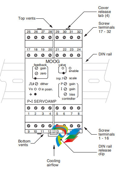
3 Installation 3.1 Placement A horizontal DIN rail, mounted on the vertical rear surface of an industrial steel enclosure, is the intended method of mounting. The rail release clip of the G122-829A001 should face down, so the front panel and terminal identifications are readable and so the internal electronics receive a cooling airflow. An important consideration for the placement of the module is electro magnetic interference (EMI) from other equipment in the enclosure. For instance, VF and AC servo drives can produce high levels of EMI. Always check the EMC compliance of other equipment before placing the G122-829A001 close by.
3.2 Cooling Vents in the top and bottom sides of the G122-829A001 case provide cooling for the electronics inside. These vents should be left clear. It is important to ensure that equipment below does not produce hot exhaust air that heats up the G122-829.
3.3 Wiring The use of crimp “boot lace ferrules” is recommended for the screw terminals. Allow sufficient cable length so the circuit card can be withdrawn from its case with the wires still connected. This enables switch changes on the circuit card to be made while the card is still connected and operating. An extra 100mm, for cables going outside the enclosure, as well as wires connecting to adjacent DIN rail units, is adequate. The screw terminals will accommodate wire sizes from 0.2mm2 to 2.5mm2 (24AWG to 12AWG). One Amp rated, 0.2mm2 should be adequate for all applications.
3.4 EMC The G122-829A001 emits radiation well below the level called for in its CE mark test. Therefore, no special precautions are required for suppression of emissions. However, immunity from external interfering radiation is dependent on careful wiring techniques. The accepted method is to use screened cables for all connections and to radially terminate the cable screens, in an appropriate grounded cable gland, at the point of entry into the industrial steel enclosure. If this is not possible, chassis ground screw terminals are provided on the G122-829A001. Exposed wires should be kept to a minimum length. Connect the screens at both ends of the cable to chassis ground.
6.2 Input 1 An input to the error amplifier: This input is ±10V non-inverting and has two important features: It has a scale pot on its input that enables large inputs to be scaled down to match smaller signals on other inputs. Scale range is 10 to 100%. Set fully clockwise (FCW), an input of 100V can match a 10V signal on the other inputs. Note that the maximum permissable input voltage is ±95V. It has a switch selectable (SW4:2) lag of 55mS that can be used to remove transients from the input signal that could cause unwanted rapid movement in the output. Input 1 is well suited to be a command because of these two features. If input 1 is used for feedback, be sure the lag is switched off. Input resistance after the scale pot is 94k Ohms. 6.3 Input 2 An input to the error amplifier: This input is differential, with non-inverting and inverting inputs. It is switch selectable (SW5) between 4-20mA and ±10V. The 4-20mA converter produces 0 to +10V for 4 to 20mA input to terminal 7. R34 connects from the output of the amplifier to the input of the error amp. It is a plug-in resistor with a default value of 100k Ohms, giving a nominal ±10V input signal range when V is selected. Input 2 is suitable for command or feedback. R34 can be increased to give a larger input range. Terminal 8. the inverting input, can be connected to ground with SW6:1. 6.4 Input 3 An input to the output summing and limiting amplifier via a plug-in resistor, R33. A typical use for this input is command feed forward or closing the outer loop of a three stage valve. With R33 at 10k Ohm, a ±10V input will produce ±100% valve drive. Increasing R33 reduces the valve drive. The summing amp gain can be changed with plug-in resistor R27. This is useful if input 3 is being used to close the outer loop of a three stage valve. 7 Output configuration Select the output to match the input requirements of the valve (SW2). When voltage (V) is selected, ±10V is available into a minimum load of 200 Ohm. When current (I) is selected, the current level switches (SW1:X) enable ±5 to ±100mA to be selected. The switch selections sum, so, if for instance 45mA is required, select 30.10 and 5. The output can drive all known Moog valves up to ±100mA. The maximum load at I (Amp) output is: RL max = 11V – 39 Ohm I (Amp) eg. at 50mA RL max is 181 Ohm When 4-20mA is selected, the output V/I switches must be in I and the output current SW1 must have switch 3 selected for 20mA. Maximum load for 4-20mA output is 500 Ohm. The output amplifier is limited to approximately 105% of the selected full scale output. If both the proportional and integrator stages are saturated, the output will not be twice the selected full scale but still only 105% of full scale. 8 Step push button The step push button (SW3) injects -50% valve drive disturbance into the output. When released, the valve drive reverts to its original level. This feature is useful for closed loop gain optimisation.
9 P-I selection For position closed loops, initially select only P (SW6:2). For pressure or velocity loops select I (SW6:4) initially and then P. See paragraph 12 below for more detail. For a complete discussion of P and I control, see the G122-202 servoamplifier Application Notes (part no C31015). 10 Integrator input The servoamplifier has a unity gain input error amplifier followed by two parallel stages, one a proportional amplifier and the other an integrator. The outputs of these two stages can be switched to the output power amplifier (see paragraph 7 above) which then drives the valve. The input to the integrator stage can be switch selected (SW4:1) from either the output of the error amplifier, I in = E, or the output of the proportional stage, I in = P. The latter arrangement is used in the G122-202. It is beyond the scope of these Application Notes to detail the benefits of each arrangement. If you have experience with the G122-202. I in = P would seem to be an easy choice. 11 P only gain For position loops select only P control (SW6:2). Input a step disturbance of 50% valve current with the step push button (SW3). Adjust the P gain for the required stability, while monitoring the front panel valve test point, or the feedback signal. The gain range of the proportional amplifier can be moved by changing the plug-in resistor R17. The value loaded when shipped is 100k Ohms, which gives a 1 to 20 range. Selecting 200k Ohms will give 2 to 40. The circuit will function correctly with the value of R17 between 100k Ohms and 10M Ohms. Note that as P gain is increased, the movement due to the step push button decreases. 12 P and I gains together If you are inexperienced with integral control the following set-up method is a good starting point. I in = E: Initially select only I (SW6:4). Press the step push button (SW3). Increase I gain until one overshoot in the feedback signal is observed. Next select P (SW6:2) and I (SW6:4) together and increase the P gain to reduce the overshoot. For the I in = E arrangement the P and I sequence could be reversed. i.e.: adjust P first, followed by I. I in = P: For an I in = P arrangement, only the “P followed by I” sequence of adjustment can be used. For a more thorough discussion see G122-202 Application Notes (part no C31015). 13 I limit The contribution from the integrator to the output amplifier can be reduced by selecting I limit on (SW6:3). When this switch is on the integrator contribution is reduced to approximately 15% of the level when it is off. This feature is useful in a position loop that may require integral control to achieve the required steady state accuracy. The limited integral control removes valve null error when the final position is reached. It is also useful in a pressure loop to limit overshoot, if the valve drive saturates.
| User name | Member Level | Quantity | Specification | Purchase Date |
|---|


-
 Honeywell HC900 Process and Safety Controller
 -
 ABB ControlMaster CM10 Universal Process Controller
 -
 ABB dual power conversion switch
 -
 ABB RET 541/543/545 Transformer Terminal Device
 -
 ABB Relion ® RET620 Transformer Protection and Control Device
 -
 ABB Relion ® REU615 Voltage Protection and Control Device
 -
 ABB Relion ® REU615 Voltage Protection and Control Device
 -
 ABB REX615 Protection and Control Relay Products
 -
 ABB PGC2000 series E2 process gas chromatograph
 -
 ABB PROCOLOR P 88QT03 bus coupling module
 -
 Honeywell WEB-8000 Controller
 -
 ABB Protection Relay REX 521
 -
 ABB 5SGY3545L0020 Controller Module
 -
 ABB 5SGY3545L0017 module tension controller
 -
ABB 5SGY3545L003 IGCT control module
-
ABB SNAT609TAI 5761789-6H Industrial I/O Interface Card
-
 ABB SNAT602TAC circuit board
 -
 ABB SNAT603 CNT Control Board
 -
 ABB SNAT634PAC pulse amplifier module
 -
 ABB RK682011-BA RL0B 100 standard unit module
 -
 ABB PP846A 3BSE042238R2 Industrial Control Panel
 -
 ABB ZMU-02 inverter memory card
 -
 ABB 3BHE014135R0011 UAD149A0011 DCS POSITIONING CONTROL MODULE
 -
 ABB 3BHE014135R0011 UAD149 A00-0-11 I/O module
 -
 ABB MEASUREMENT & ANALYTICS Web Tension Systems with Tension Electronics PFEA113
 -
 ABB GDD471A001 2UBA0022R0001 motor control module
 -
ABB UCD224A103 high-performance control module
-
 ABB PDD205A0121 control module
 -
 ABB PDD205A1121 3BHE02535R1211 processor module
 -
 ABB DSDX453 Digital Input/Output Module
 -
 ABB DSPC454 controller module
 -
 Woodward ESDR4 Current Differential Protection Relay
 -
 Siemens SIJECT CI16iP StepB 6AТ1131-6DF21-0AB0 Compact Control
 -
 EtherNet/IP™ to Remote I/O or DH+ Gateway AN-X2-AB-DHRIO
 -
 ABB 81EU01-E/R3210 Analog Signal Input Module
 -
 ABB TK457V050 Industrial Temperature Controller
 -
 ABB DSRF197K01 Control Module
 -
 ABB TK802F SD802F/SD812F power cord
 -
 ABB 3BHE03930R0101 I/O module
 -
ABB 3BHB0040277R0101 GVC700AE01 thyristor module
-
 ABB 3BHB003154R0101 5SXE05-0156 IGCT module
 -
 RELIANCE INSPECTOR VCIB-06 Advanced Industrial Visual Display
 -
ABB AO2000-LS25 Laser analyzer
-
 HIMA F8650X Central module
 -
ABB PM864AK01 Classic System 800xA hardware selector
-
 ABB 3BSE048845R1 CI868K01 IEC 61850 Interface
 -
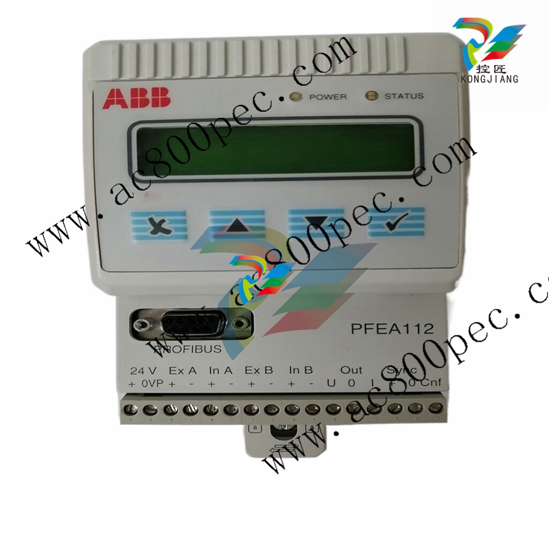 ABB 5SHY35L4520 Asymmetric Integrated Gate Converter Thyristor
 -
 ABB UNS0119A-P V101 3BHE029153R0101 processor module
 -
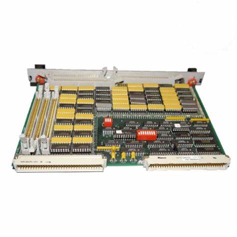
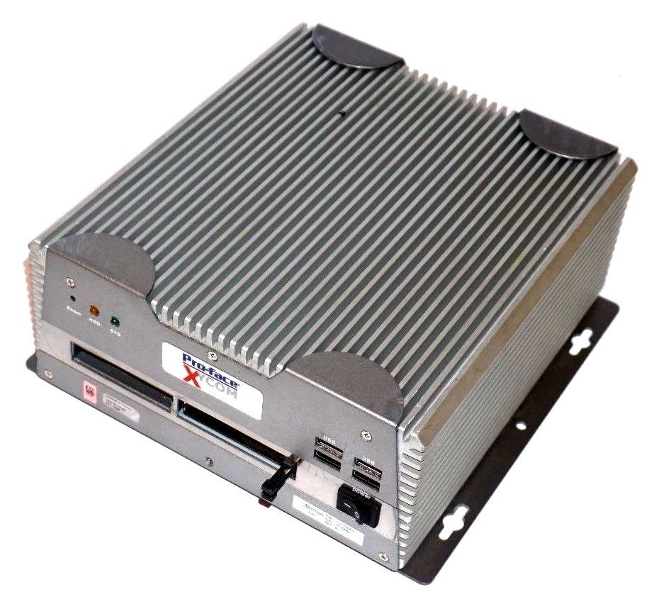
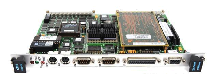
 Xycom 99212A-001 PC board
 -
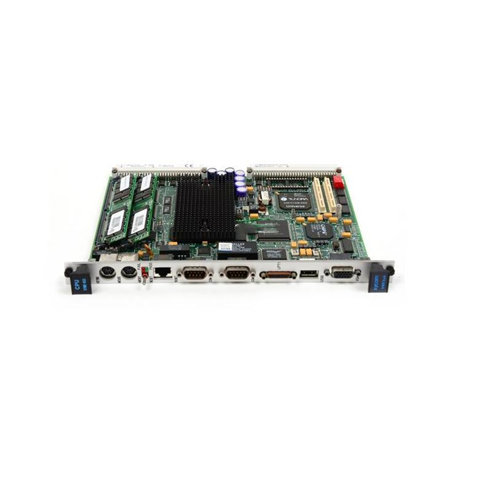
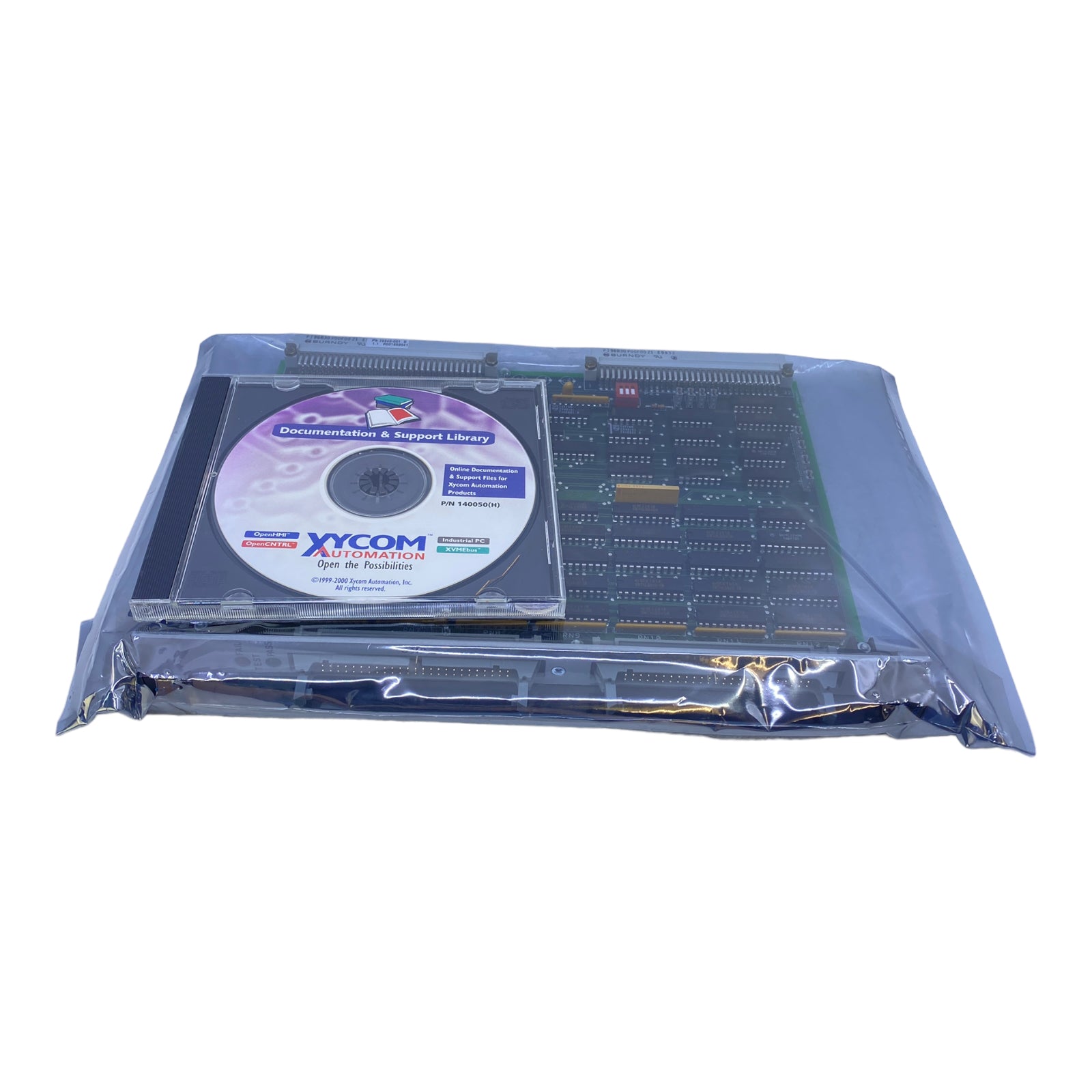
 Xycom 144365-001 motherboard
 -
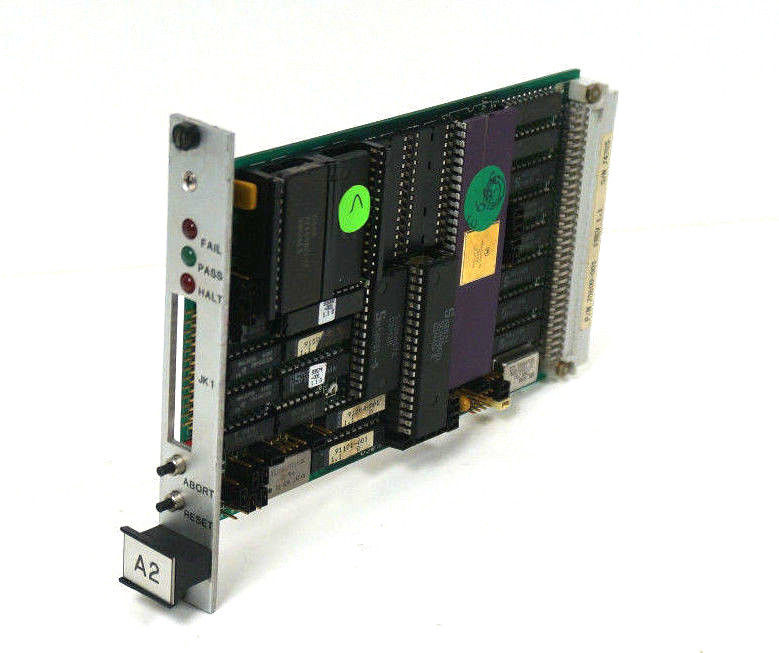
 XYCOM 70400-001 T3065-4 XVME-400 Board
 -
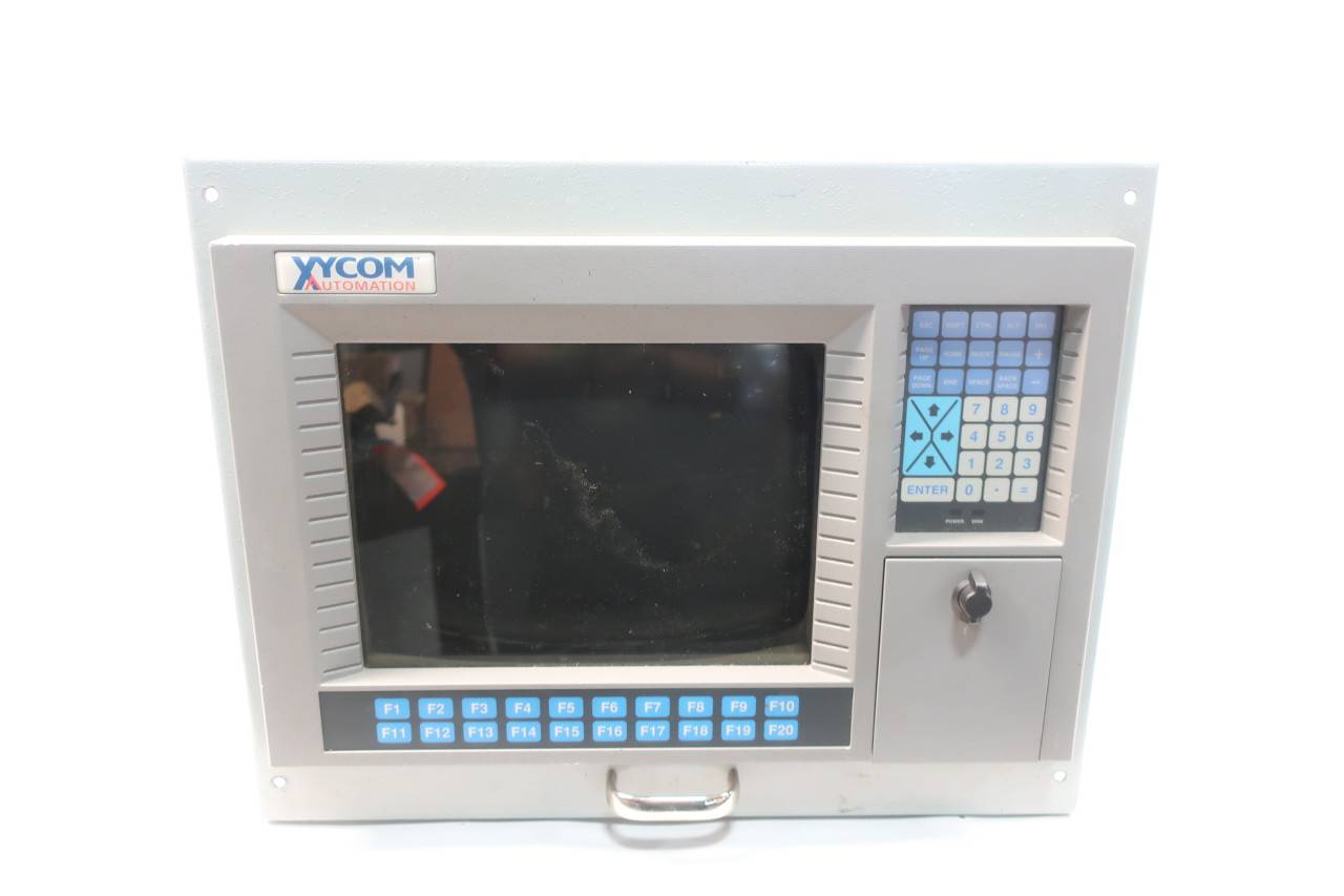 Xycom Automation # 9450-2480016010000 Interface Monitor Model
 -
 XYCOM 70560-001 AIN XVME-560, VMEbus module card, PCB board
 -
 Xycom XVME-491 VMEbus 71491A PN70491-001
 -
 Xycom 99157-001 Circuit Board
 -
 Xycom 1341 egemin PM-070016 computer P/N 701301-01 TF-AEC-6910-C13
 -
 Xycom 8430 Industrial Controller Options 71338 115/230V P/N 8430-078122A002110
 -
 Xycom XVME-203 VME Digital Counter I/O Module Board PLC 70203-001
 -
 ABB UNS0119A-P V101 Controller Module
 -
 ABB GCC960C103 3BHE033067R0103 Controller Module
 -
 ABB GVC736CE101 High Performance AC Inverter
 -
 ABB PCD244A101 Terminal Card Module
 -
ABB 3BHE020356R0101 GFD212A motor thermal relay
-
ABB PDD500A101 power distribution module
-
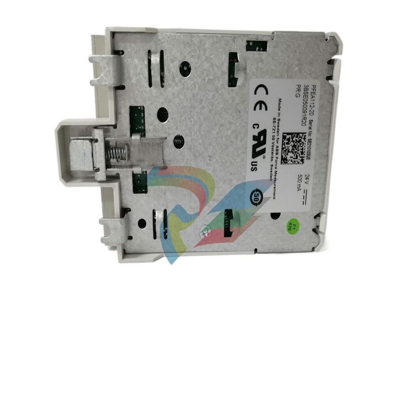 ABB PDD200A101 Industrial Control Module
 -
 Xycom 86863BA Control Card 86864-003/B
 -
 Xycom XVME-240 Digitale I/O-Karte für industriellen Einsatz
 -
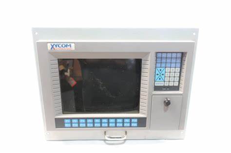 Xycom 9450 PC/AT computer operator interface HMI screen display keyboard control
 -
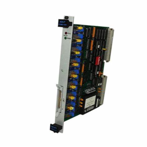 XYCOM XCME-540 Analog I/O Module VMEBUS 70540-001
 -
 XYCOM 9460 Touch Screen
 -
 Xycom Analog CDA XVME VME TI DSP SCSI I/O module sequence RS232 card board
 -
 ALSTOM MCGG62N1CB0753F Auxiliary Transmission Relay
 -
 ABB S3N 3P 150A Standard thermal-magnetic
 -
 ABB SPIET800 Ethernet CIU Transfer Module
 -
 ABB SPAD 346 C3 Differential Protection
 -
 ABB 15.04.2005 Instrument Transformer
 -
 ABB FPX86-9329-C High Performance Industrial Controller
 -
 ABB ARCOL 0346 Industrial Control Module
 -
ABB ARCOL 0338 Controller Module
-
ABB ARCOL 0339 Industrial Inverter
-
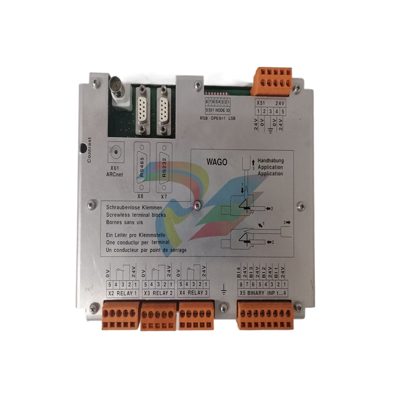 ABB 969-54 New Automation Controller Module DCS PLC Module
 -
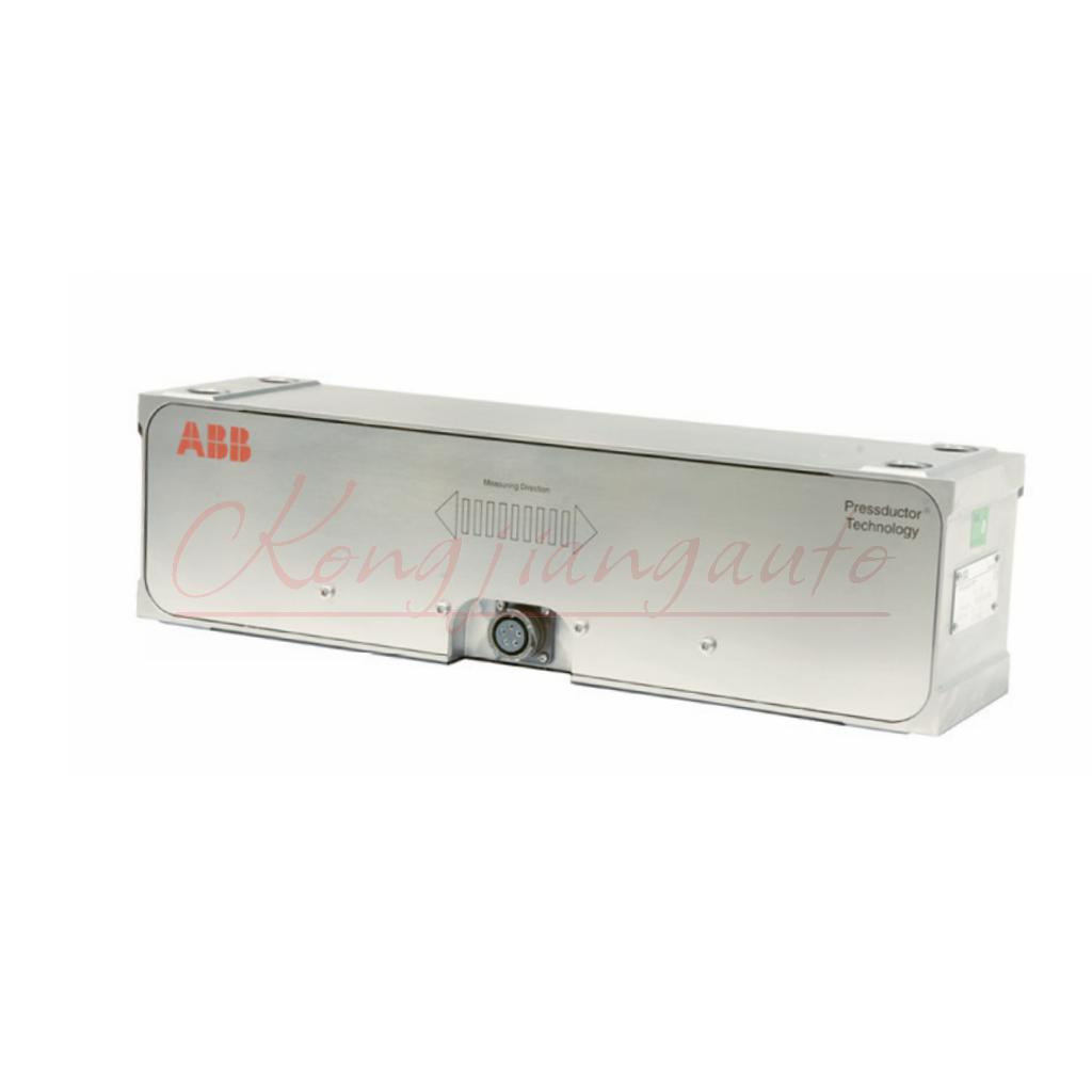 ABB 5SDD1060F0001 diode disk module
 -
ABB 5SDF0860H0003 Gate Cut off Thyristor Module
-
 ABB KUC720AE01 Industrial High Frequency Control Module
 -
 ABB KUC720AE - High Performance Industrial Control Module
 -
ABB UFC718AE01 high-performance main circuit interface
-
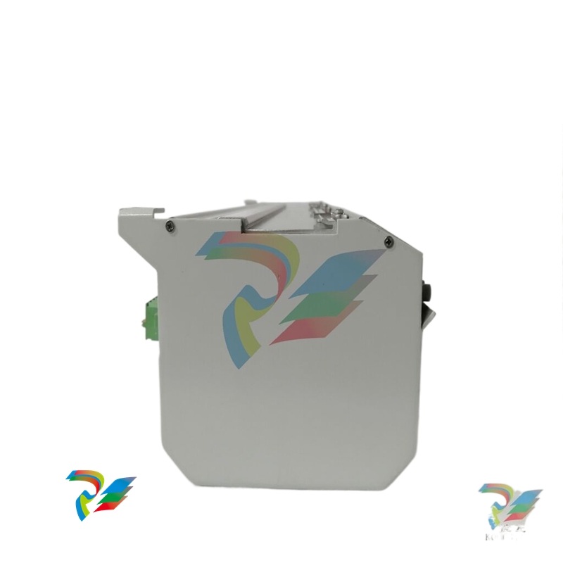 ABB 5SHX2645L0004 Integrated Gate Converter Thyristor
 -
 Xycom 2000-KB1 94687-001 keyboard
 -
 Xycom 141452-001 5-slot amplifier card 141452001
 -
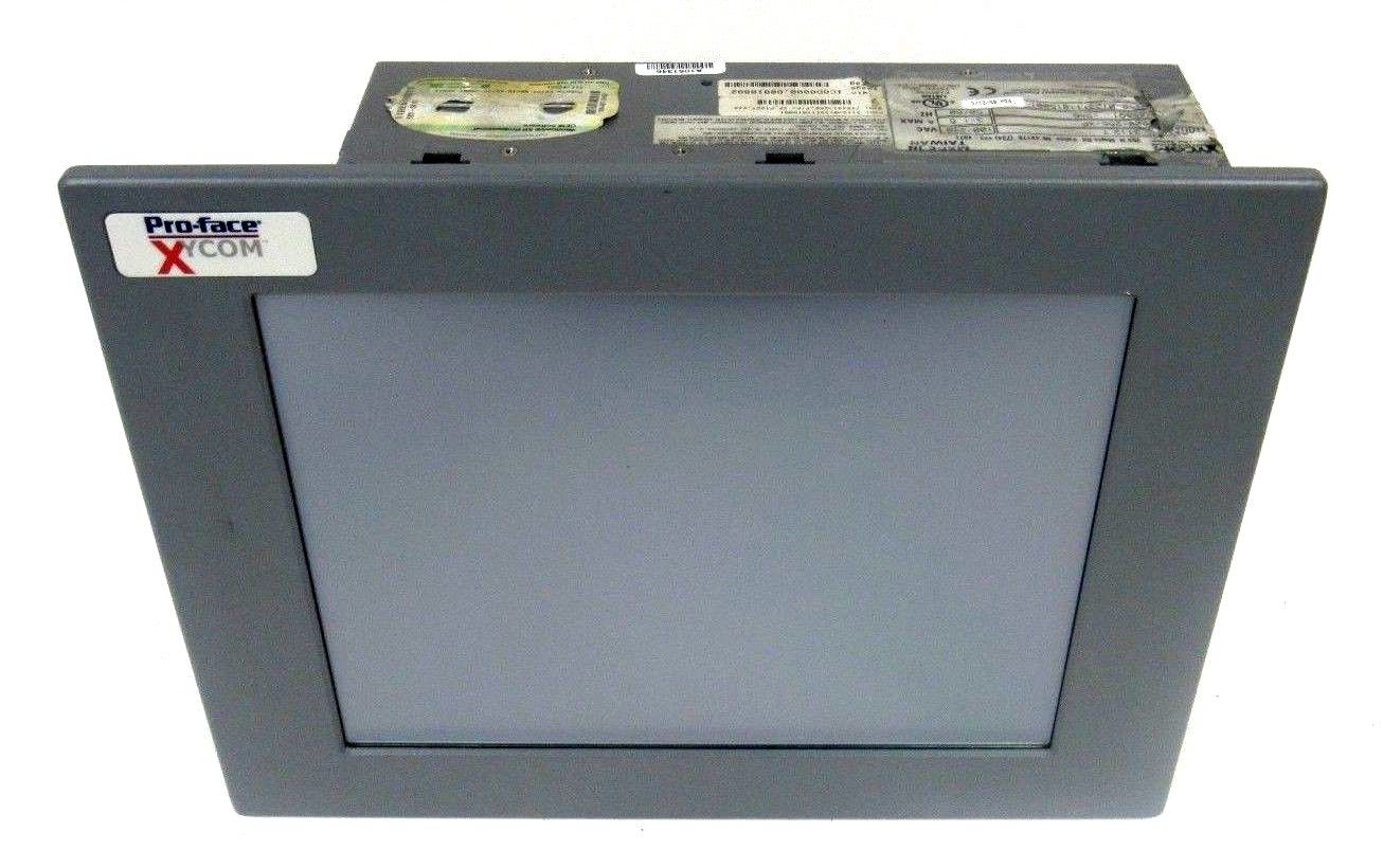
 Xycom 5015T/R2, Pro-face LCD 15" Monitor
 -
 Xycom 95212B-001 Module Circuit Board Card 95213-007 8503 PCB PWA Programmable Logic Controller
 -
 Xycom XVME-957 71957C-001 Circuit Board
 -
 XYCOM 99157-001 Circuit Board
 -
 Xycom 4115 T Operator Interface Panel 100-240v-ac
 -
 Xycom 2005 CRT Direct REPLACMENT LCD with Cable Kit
 -
 Xycom 4850 LCD monitor upgrade with cable kit 12 inches
 -
 Xycom 4810A 9-inch CRT LCD monitor upgrade
 -
ABB KOFA12D3 Indoor current transformers
-
.jpg) WOODWARD ProAct Positioner (Flex I/O)
WOODWARD ProAct Positioner (Flex I/O) -
.jpg) WOODWARD ProAct Positioner (16 pin), 3rd Generation
WOODWARD ProAct Positioner (16 pin), 3rd Generation -
 WOODWARD ProAct 75 Speed Control ( 1st Generation)
 -
.jpg) WOODWARD R-Series Actuators
WOODWARD R-Series Actuators -
.jpg) WOODWARD F-Series Positioners
WOODWARD F-Series Positioners -
 WOODWARD DVP Digital Valve Positioner
 -
.jpg) WOODWARD GSOV25HT Gas Fuel Shutoff Valve, 2.0”Flange
WOODWARD GSOV25HT Gas Fuel Shutoff Valve, 2.0”Flange -
.jpg) WOODWARD GSOV80 Gas Fuel Shutoff Valve, 2.0” Flange
WOODWARD GSOV80 Gas Fuel Shutoff Valve, 2.0” Flange -
 WOODWARD USOV Universal Shutoff Valves
 -
.jpg) WOODWARD LSOV25 Liquid Fuel Shutoff Valve
WOODWARD LSOV25 Liquid Fuel Shutoff Valve -
 WOODWARD LQ25 Standard Valves
 -
WOODWARD LQ6 Liquid Fuel Valve Actuator with On-board Driver
-
.jpg) WOODWARD GS50 Gas Fuel Valve Actuator with On-board Driver
WOODWARD GS50 Gas Fuel Valve Actuator with On-board Driver -
.jpg) WOODWARD GS40 Gas Fuel Valve Actuator with On-board Driver
WOODWARD GS40 Gas Fuel Valve Actuator with On-board Driver -
 WOODWARD Turbine Shutdown Trip Block Assemblies
 -
.jpg) WOODWARD TM Actuators (Linear)
WOODWARD TM Actuators (Linear) -
.jpg) WOODWARD CPC-II Current-to-Pressure Converter
WOODWARD CPC-II Current-to-Pressure Converter -
.jpg) WOODWARD UG Actuators
WOODWARD UG Actuators -
WOODWARD UG25+ Actuators
-
WOODWARD UG25+ Governors for Steam Turbines
-
.jpg) WOODWARD TGE Turbine Actuators
WOODWARD TGE Turbine Actuators -
 WOODWARD TG611 speed controller
 -
.jpg) WOODWARD TG Turbine Governors
WOODWARD TG Turbine Governors -
 WOODWARD MicroNet™ System Modules
 -
.jpg) WOODWARD Flex500 Platform
WOODWARD Flex500 Platform -
WOODWARD 2300E Electronic Load Sharing and Speed Controls
-
.jpg) WOODWARD 5009XT Steam Turbine Controls
WOODWARD 5009XT Steam Turbine Controls -
.jpg) WOODWARD 505 Steam Turbine Controls
WOODWARD 505 Steam Turbine Controls -
WOODWARD Peak200 Steam Turbine Controls
-
.jpg) WOODWARD 2301E-ST Steam Turbine Controls
WOODWARD 2301E-ST Steam Turbine Controls

