

K-WANG


- Telephone:+86-15305925923
- contacts:Mr.Wang
- Email:wang@kongjiangauto.com
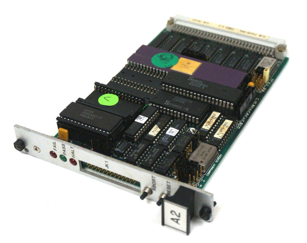
PURPOSE The purpose of this document is to describe the features of the Advanced Micro Controller 2, providing basic information in a datasheet form.
GE FANUC T1693EN Liquid Cooled DELTA
AEM
Active Energy Management
CDC
Common Drive Controller
CDM
Complete Drive Module
DDM
Drive Data ManagerTM
DELTA
Generic term for the transistor module or rectifier unit in the DELTA modular drive
DFE
Diode Front End
DIB
DELTA Interface Board
Drive
Cubiclised DELTA components (CDM)
DNV
Det Norske Veritas
I/O
Input /Output
IEC
International Electro-technical Committee
IGBT
Insulated Gate Bipolar Transistor
Machine Bridge
The machine bridge controls the bi-directional power flow between the d.c. link and
the motor or generator
MVM
Mains Voltage Monitor
Network Bridge
The network bridge controls the power flow from the mains supply into the d.c. link.
In the case of an AEM system, bi-directional power flow between the supply and the
d.c. link is controlled.
PDS
Power Drive System
PWM
Pulse Width Modulation
SFE
Sinusoidal Front End
SMPS
Switch Mode Power Supply
System
General term for the PDS
UNITS COVERED
LIQUID COOLED DELTA POWER MODULES
MVDL643-4702
Transistor Module 643 A, 690V a.c. 1200Vd.c.
MVDL800-47xx
Transistor Module 800 A, 690 Va.c. 1250Vd.c.
MVDL800-XXxxXXX
Transistor Module 800 A, 690 Va.c. 1250Vd.c
MVDL1000-47xx
Transistor Module 1000 A,690Va.c.1250Vd.c.
MVDL1000-xxxxxxx
Transistor Module 1000 A, 690Va.c. 1250Vd.c
MVRL2100-4601
Rectifier Module 2100 A,690Va.c.
MVRL2100-4602
Rectifier Module 2100 A, 690V a.c.Hosetail connection.
DFE NETWORK BRIDGE SHARING REACTORS
50Z0081/01
3 phase, 986 A, 690Va.c.
AEM AND MACHINE BRIDGE SHARING REACTORS
50Z0126/01
3 phase, 645 A, 690Va.c.
5020126/02
3 phase, 800 A, 690Va.c.
50Z0126/03
3 phase, 1000 A, 690Va.c.
DELTA CONTROL COMPONENTS
MVC3001-400x
MV3000e Controller
MVC3002-4001
User I/O Termination Panel
MVC3003-40xx
Switched Mode Power Supply
MVC3006-400x
Mains Voltage Monitor
MVS3000-4001
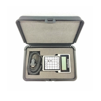
Drive Data ManagerT™(Keypad)
MVS3001-4001
Drive Data Manager T™(Keypad) Mounting Kit
DELTA RIBBON CABLES +ACCESSORIES
MVS3017-4001
16way Ribbon Cable Earthing Clamp
MVS3018-400x
40way Ribbon Cable Earthing Clamp
MVS3019-4001
50way Ribbon Cable Earthing Clamp
MVS3020-40xx
40way Screened Ribbon Cable
LIQUID COOLED DELTA MOUNTING FRAMES FOR RITTAL TS8 ENCLOSURE
MVDL-TS-4001
Liquid Cooled DELTA Mounting Kit 800Dx600W
MVDL-TS-4002
Liquid Cooled DELTA Mounting Kit 800Dx800W
MVDL-TS-4003
Liquid Cooled DELTA Mounting Kit 800Dx 1000W
MVDL-TS-4004
Liquid Cooled DELTA Mounting Kit 800Dx1200W
MVDL-TS-4005
Liquid Cooled DELTA Mounting Kit 600Dx 600W
MVDL-TS-4006
Liquid Cooled DELTA Mounting Kit 600Dx800W
MVDL-TS-4007
Liquid Cooled DELTA Mounting Kit 600Dx1000W
MVDL-TS-4008
Liquid Cooled DELTA Mounting Kit 600Dx 1200W
1.
INTRODUCTION
1.1
GENERAL DESCRIPTION
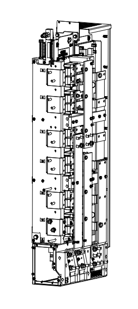
An MV3000e DELTA a.c. drive is used to control a motor, generator, or power conditioning application.
It uses a modular approoch which allows the use of a small number of common components to create a
large number of system variants.
1.1.1 Advantages Of The Modular System
The DELTA transistor and rectifier modules are of a standard mechanical design, using the
same mounting method and dimensions:
DELTA rectifier and transistor modules can be connected in parallel to provide a wide range of
power levels;
Modular construction makes maintenance and repair work simple, and enables rapid module
replacement;
.
DELTA transistor and rectifier modules can be withdrawn on a simple slide system for ease of
assembly and maintenance.
Ease of handling - smaller, lighter modules are assembled to form large drives.
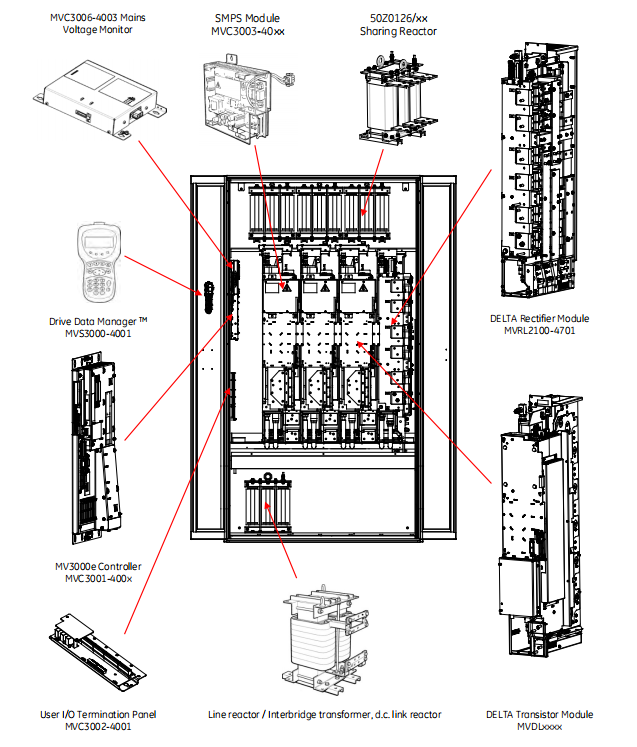
1.1.2
DELTA Product Range
Rectifer module:
Transistor modules;
MV3000e Controller
SMPS (Switch Mode Power Supply) units;
User I/O termination panel;
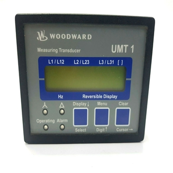
MVM (Mains Voltage Monitor;
DDM (Drive Data Manager™- Keypad;
Reactors and transformers;
Installation accessories (mounting kits and control cables).
1.2
ASSOCIATED MANUALS
T1676-MV3000e Getting Started Manual (for rectifier fed systems);
T1679-MV3000e Software Manual (and Firmware SupplementT21541;
T2002-MV3000e Getting Started Manual (for AEM systems).
The T1676 and T2002 manuals include commissioning and operating details for the complete MV3000e
DELTA drive.
The T1676,T1679 and T2002 manuals should be regarded as part of the DELTA product.Individual DELTA
component instructions sheets that may also be required are shown below.
T1694
MVS3007-4002-Profibus Field Coupler 12 Mb/s;
T1915
MVS3000-4001-Drive Data Manager ™(keypod);
T1916
MVS3001-4001-Keypad mounting kit;
T1930
MVC3006-4003- Mains Voltoge Monitor (MVM);
T1968
MVS3011-4001-CANbus communications module,
T1973
MVC3003-40xx - Switch Mode Power Supply (SMPS) Module;
T2034
MVS3012-400x-Ethernet interfoce;
T2100
MVDL800 DELTA Transistor Module;
T2101
MVDL1000 DELTA Transistor Module,
T2112
MVC3001-400x-DELTA Controller.
2.
SPECIFICATION
2.1
INTRODUCTION
The specifications provided in this section are for the individual DELTA components.These components are
the transistor and rectifier modules, the MV3000e Controller,the Switched Mode Power Supply (SMPS), the
User I/O Termination Panel, associated reactors and transformers and the installation occessories (for use
in endosures).Consideration should be given to the rating of individual components when they are
indluded in a CDM as derating for parallel applications may apply.
2.2
DELTA COMPONENTS (GENERAL ENVIRONMENT)
All DELTA components are designed to comply with the common specifications in Table 2-1 to Table 2-6
unless otherwise detailed in the individual component specification.Drive performance data for an
MV3000e based DELTA drive is indluded in Table 2-7.
2.2.1
Electrical Supply
DELTA modules are intended to be used in a drive connected to an electrical supply with the following
characteristics:
FUNCTION
SPECIFICATION
Electrical Supply
TN or TT (i.e. earthed/grounded neutrall.
Network Type
Can also be connected to IT network (i.e. isolated or high impedance neutral) if IT network
separated from public mains supply by an isolating transformer
Isee Section 4.5.1: Protection Against Transients).
Voltoge Range
575 V-690V(600V nominal)
Voltage Variation
(on voltage range)
±10% long term,±15% for 0.5 to 30 cycles with loss of performance but no trip
Voltage Unbalance
Negative sequence voltage not to exceed 3%
Frequency loptimised)
50Hz,60 Hz
Operational Frequency
45 Hz to 63 Hz.With frequencies outside the optimised values, extra d.c. link ripple may
Range
be apparent and may impair motor control performance.
Insulation Coordination
EN 50178,IEC 61800-5-1,UL 840,CSA C22.2 No.0.2
TN or TT network
: Overvoltage Category Ill
Overvoltage Category
IT network
: Overvoltoge Category ll
(line to earth)
For full compliance with UL 508C, transient suppressers complying with UL 1449 must be
fitted between line and earth. These must be fitted as close as possible to the point
where the electrical supply enters the drive enclosure.
Table 2-1.-Electrical Specification
2.2.2
Switching Frequency
The switching frequency is set by parameter P35.00 in the MV3000e controller (see MV3000e Software
Manual T16791.The range of possible switching frequencies is given in Table 2-2.
Default
Alternatives Available
Network Bridge(AEM only)
2.5kHz
5kHz
Machine Bridge
1.25kHz
2.5kHz,5kHz
Notes:
1.If one of the alternative switching frequencies is selected, it may be necessary to reduce the power rating
of the drive, particularly at higher ambient temperatures.
2. lf the switching frequency of the network bridge is altered, the effects on the PWM filter must be
assessed.The change of PWM frequency will affect the power dissipation in the filter and will also affect
the emissions onto the electricity supply.
| User name | Member Level | Quantity | Specification | Purchase Date |
|---|


-
 Honeywell HC900 Process and Safety Controller
 -
 ABB ControlMaster CM10 Universal Process Controller
 -
 ABB dual power conversion switch
 -
 ABB RET 541/543/545 Transformer Terminal Device
 -
 ABB Relion ® RET620 Transformer Protection and Control Device
 -
 ABB Relion ® REU615 Voltage Protection and Control Device
 -
 ABB Relion ® REU615 Voltage Protection and Control Device
 -
 ABB REX615 Protection and Control Relay Products
 -
 ABB PGC2000 series E2 process gas chromatograph
 -
 ABB PROCOLOR P 88QT03 bus coupling module
 -
 Honeywell WEB-8000 Controller
 -
 ABB Protection Relay REX 521
 -
 ABB 5SGY3545L0020 Controller Module
 -
 ABB 5SGY3545L0017 module tension controller
 -
ABB 5SGY3545L003 IGCT control module
-
ABB SNAT609TAI 5761789-6H Industrial I/O Interface Card
-
 ABB SNAT602TAC circuit board
 -
 ABB SNAT603 CNT Control Board
 -
 ABB SNAT634PAC pulse amplifier module
 -
 ABB RK682011-BA RL0B 100 standard unit module
 -
 ABB PP846A 3BSE042238R2 Industrial Control Panel
 -
 ABB ZMU-02 inverter memory card
 -
 ABB 3BHE014135R0011 UAD149A0011 DCS POSITIONING CONTROL MODULE
 -
 ABB 3BHE014135R0011 UAD149 A00-0-11 I/O module
 -
 ABB MEASUREMENT & ANALYTICS Web Tension Systems with Tension Electronics PFEA113
 -
 ABB GDD471A001 2UBA0022R0001 motor control module
 -
ABB UCD224A103 high-performance control module
-
 ABB PDD205A0121 control module
 -
 ABB PDD205A1121 3BHE02535R1211 processor module
 -
 ABB DSDX453 Digital Input/Output Module
 -
 ABB DSPC454 controller module
 -
 Woodward ESDR4 Current Differential Protection Relay
 -
 Siemens SIJECT CI16iP StepB 6AТ1131-6DF21-0AB0 Compact Control
 -
 EtherNet/IP™ to Remote I/O or DH+ Gateway AN-X2-AB-DHRIO
 -
 ABB 81EU01-E/R3210 Analog Signal Input Module
 -
 ABB TK457V050 Industrial Temperature Controller
 -
 ABB DSRF197K01 Control Module
 -
 ABB TK802F SD802F/SD812F power cord
 -
 ABB 3BHE03930R0101 I/O module
 -
ABB 3BHB0040277R0101 GVC700AE01 thyristor module
-
 ABB 3BHB003154R0101 5SXE05-0156 IGCT module
 -
 RELIANCE INSPECTOR VCIB-06 Advanced Industrial Visual Display
 -
ABB AO2000-LS25 Laser analyzer
-
 HIMA F8650X Central module
 -
ABB PM864AK01 Classic System 800xA hardware selector
-
 ABB 3BSE048845R1 CI868K01 IEC 61850 Interface
 -
 ABB 5SHY35L4520 Asymmetric Integrated Gate Converter Thyristor
 -
 ABB UNS0119A-P V101 3BHE029153R0101 processor module
 -
 Xycom 99212A-001 PC board
 -
 Xycom 144365-001 motherboard
 -
 XYCOM 70400-001 T3065-4 XVME-400 Board
 -
 Xycom Automation # 9450-2480016010000 Interface Monitor Model
 -
 XYCOM 70560-001 AIN XVME-560, VMEbus module card, PCB board
 -
 Xycom XVME-491 VMEbus 71491A PN70491-001
 -
 Xycom 99157-001 Circuit Board
 -
 Xycom 1341 egemin PM-070016 computer P/N 701301-01 TF-AEC-6910-C13
 -
 Xycom 8430 Industrial Controller Options 71338 115/230V P/N 8430-078122A002110
 -
 Xycom XVME-203 VME Digital Counter I/O Module Board PLC 70203-001
 -
 ABB UNS0119A-P V101 Controller Module
 -
 ABB GCC960C103 3BHE033067R0103 Controller Module
 -
 ABB GVC736CE101 High Performance AC Inverter
 -
 ABB PCD244A101 Terminal Card Module
 -
ABB 3BHE020356R0101 GFD212A motor thermal relay
-
ABB PDD500A101 power distribution module
-
 ABB PDD200A101 Industrial Control Module
 -
 Xycom 86863BA Control Card 86864-003/B
 -
 Xycom XVME-240 Digitale I/O-Karte für industriellen Einsatz
 -
 Xycom 9450 PC/AT computer operator interface HMI screen display keyboard control
 -
 XYCOM XCME-540 Analog I/O Module VMEBUS 70540-001
 -
 XYCOM 9460 Touch Screen
 -
 Xycom Analog CDA XVME VME TI DSP SCSI I/O module sequence RS232 card board
 -
 ALSTOM MCGG62N1CB0753F Auxiliary Transmission Relay
 -
 ABB S3N 3P 150A Standard thermal-magnetic
 -
 ABB SPIET800 Ethernet CIU Transfer Module
 -
 ABB SPAD 346 C3 Differential Protection
 -
 ABB 15.04.2005 Instrument Transformer
 -
 ABB FPX86-9329-C High Performance Industrial Controller
 -
 ABB ARCOL 0346 Industrial Control Module
 -
ABB ARCOL 0338 Controller Module
-
ABB ARCOL 0339 Industrial Inverter
-
 ABB 969-54 New Automation Controller Module DCS PLC Module
 -
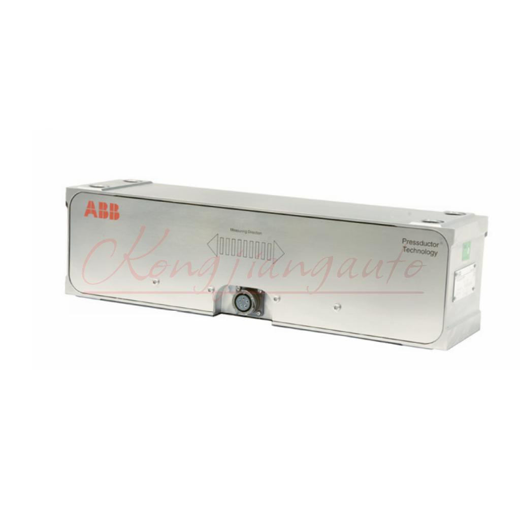 ABB 5SDD1060F0001 diode disk module
 -
ABB 5SDF0860H0003 Gate Cut off Thyristor Module
-
 ABB KUC720AE01 Industrial High Frequency Control Module
 -
 ABB KUC720AE - High Performance Industrial Control Module
 -
ABB UFC718AE01 high-performance main circuit interface
-
 ABB 5SHX2645L0004 Integrated Gate Converter Thyristor
 -
 Xycom 2000-KB1 94687-001 keyboard
 -
 Xycom 141452-001 5-slot amplifier card 141452001
 -
 Xycom 5015T/R2, Pro-face LCD 15" Monitor
 -
 Xycom 95212B-001 Module Circuit Board Card 95213-007 8503 PCB PWA Programmable Logic Controller
 -
 Xycom XVME-957 71957C-001 Circuit Board
 -
 XYCOM 99157-001 Circuit Board
 -
 Xycom 4115 T Operator Interface Panel 100-240v-ac
 -
 Xycom 2005 CRT Direct REPLACMENT LCD with Cable Kit
 -
 Xycom 4850 LCD monitor upgrade with cable kit 12 inches
 -
 Xycom 4810A 9-inch CRT LCD monitor upgrade
 -
ABB KOFA12D3 Indoor current transformers
-
.jpg) WOODWARD ProAct Positioner (Flex I/O)
WOODWARD ProAct Positioner (Flex I/O) -
.jpg) WOODWARD ProAct Positioner (16 pin), 3rd Generation
WOODWARD ProAct Positioner (16 pin), 3rd Generation -
 WOODWARD ProAct 75 Speed Control ( 1st Generation)
 -
.jpg) WOODWARD R-Series Actuators
WOODWARD R-Series Actuators -
.jpg) WOODWARD F-Series Positioners
WOODWARD F-Series Positioners -
 WOODWARD DVP Digital Valve Positioner
 -
.jpg) WOODWARD GSOV25HT Gas Fuel Shutoff Valve, 2.0”Flange
WOODWARD GSOV25HT Gas Fuel Shutoff Valve, 2.0”Flange -
.jpg) WOODWARD GSOV80 Gas Fuel Shutoff Valve, 2.0” Flange
WOODWARD GSOV80 Gas Fuel Shutoff Valve, 2.0” Flange -
 WOODWARD USOV Universal Shutoff Valves
 -
.jpg) WOODWARD LSOV25 Liquid Fuel Shutoff Valve
WOODWARD LSOV25 Liquid Fuel Shutoff Valve -
 WOODWARD LQ25 Standard Valves
 -
WOODWARD LQ6 Liquid Fuel Valve Actuator with On-board Driver
-
.jpg) WOODWARD GS50 Gas Fuel Valve Actuator with On-board Driver
WOODWARD GS50 Gas Fuel Valve Actuator with On-board Driver -
.jpg) WOODWARD GS40 Gas Fuel Valve Actuator with On-board Driver
WOODWARD GS40 Gas Fuel Valve Actuator with On-board Driver -
 WOODWARD Turbine Shutdown Trip Block Assemblies
 -
.jpg) WOODWARD TM Actuators (Linear)
WOODWARD TM Actuators (Linear) -
.jpg) WOODWARD CPC-II Current-to-Pressure Converter
WOODWARD CPC-II Current-to-Pressure Converter -
.jpg) WOODWARD UG Actuators
WOODWARD UG Actuators -
WOODWARD UG25+ Actuators
-
WOODWARD UG25+ Governors for Steam Turbines
-
.jpg) WOODWARD TGE Turbine Actuators
WOODWARD TGE Turbine Actuators -
 WOODWARD TG611 speed controller
 -
.jpg) WOODWARD TG Turbine Governors
WOODWARD TG Turbine Governors -
 WOODWARD MicroNet™ System Modules
 -
.jpg) WOODWARD Flex500 Platform
WOODWARD Flex500 Platform -
WOODWARD 2300E Electronic Load Sharing and Speed Controls
-
.jpg) WOODWARD 5009XT Steam Turbine Controls
WOODWARD 5009XT Steam Turbine Controls -
.jpg) WOODWARD 505 Steam Turbine Controls
WOODWARD 505 Steam Turbine Controls -
WOODWARD Peak200 Steam Turbine Controls
-
.jpg) WOODWARD 2301E-ST Steam Turbine Controls
WOODWARD 2301E-ST Steam Turbine Controls

