
K-WANG
+086-15305925923
Service expert in industrial control field!
Product
Article
NameDescriptionContent
Adequate Inventory, Timely Service
pursuit of excellence


Ship control system
Equipment control system
Power monitoring system
Brand
Product parameters
- Telephone:+86-15305925923
- contacts:Mr.Wang
- Email:wang@kongjiangauto.com
Description
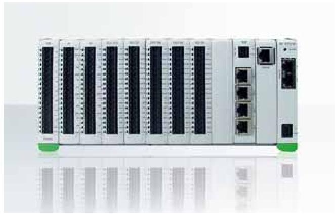
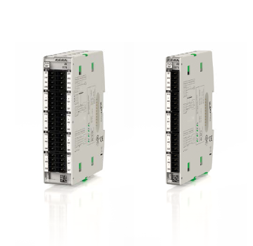
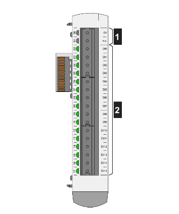
Analog Input Module (900A01-xxxx)
The Universal Analog Input module supports up to 8
user-configurable inputs on a per point basis for
thermocouple, RTD, Resistance, V, mV, mA or
slidewire. Point-to-point isolation and back-plane
isolation are provided. Modules perform analog to
digital conversion in synchronization with CPU
control execution, eliminating data interchange
latency. All analog input modules are processed in
parallel, eliminating scan time increases as modules
are added.
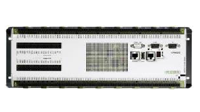
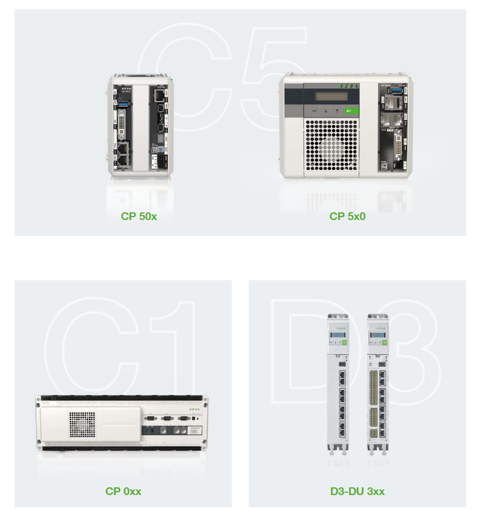
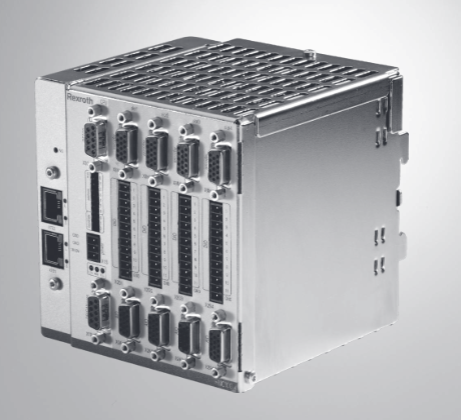
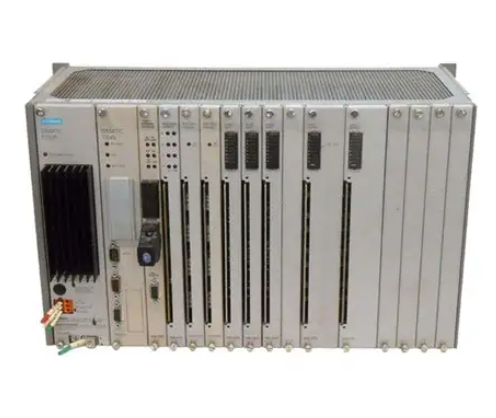
Honeywell Controller C50 CPU - SIL 900C50S-0360-00
Analog Input Module (900A01-xxxx)The Universal Analog Input module supports up to 8
user-configurable inputs on a per point basis for
thermocouple, RTD, Resistance, V, mV, mA or
slidewire. Point-to-point isolation and back-plane
isolation are provided. Modules perform analog to
digital conversion in synchronization with CPU
control execution, eliminating data interchange
latency. All analog input modules are processed in
parallel, eliminating scan time increases as modules
are added.
A green blinking status LED on the module indicates
when the module is being scanned. An amber
blinking status LED when input channels are forced
and a red status LED when module diagnostics
exist. A user-selectable failsafe value is supported
on a per channel basis. A warning signal is provided
for thermocouple inputs to indicate maintenance is
needed prior to a sensor failure. A sensor failure
signal is also provided.
Table 1 - Analog Input Specifications
Inputs per module 8 (isolated)
Input types mV, V, T/C, RTD, ohms, mA, slidewire assigned to any channel
Signal Source See Table 2 on page 7 for range types.
Thermocouple with cold junction compensation
RTD, PT100 3 wire, 40 ohms balanced maximum
Thermocouples: 100 Ohms/Leg
100 (except Low), 500 & 1000 RTD: 100 Ohms/Leg
Table 1 - Analog Input Specifications
100 YIS: 100 Ohms/Leg
100-Low RTD & 10 ohm Cu: 10 Ohms/Leg
Slidewire 100 to 6,500 Ohms: 10% of total res./leg
Input Impedance 10 megohms for T/C and mV inputs; >1 megohm for volts and 250 ohms
for mA inputs
Galvanic Input Isolation 400 VDC point to point, 1K VDC to logic
RTDs are isolated in pairs (IRTD is common to two inputs).
Noise Rejection Series Mode >60dB.
Common Mode >130dB at 120VAC.
Burnout T/C, mV, V (except for ranges below) configurable to upscale,
downscale, defined value, or none.
Volt: –500 mV to 500 mV; –1 V to 1 V; –2 V to 2 V; –5 V to 5 V; 0 V to 10
V; –10 V to 10 V; inherent to zero volt
RTD: Inherent upscale
mA: Inherent downscale
Over-range limit +/- 10% for linear ranges (volts). +/-1% for non-linear ranges (T/C, RTD).
T/C Break Detection Via current pulse
Faulty thermocouple detection If greater than 100 ohms, a warning status is provided as an output for
the AI block
Accuracy Factory configured accuracy = ± 0.1 % of range (± 0.2 % of range for 0V
to 10V and -10V to 10V)
Cold junction accuracy = ± 0.7 °C
Field calibration accuracy = ± 0.05 % of range
Reference conditions:
Temperature = 25 °C ± 3 °C (77 °F ± 5 °F)
Humidity = 45 % to 55 % RH non-condensing
Line voltage = Nominal ± 1 %
Source resistance = 0 ohm
Series mode and common mode = 0 V
Frequency = Nominal ± 1 %
Temp. Effect on Accuracy 0.01% of full scale per degree Celsius maximum
A/D Converter One per module
A/D Resolution 15 Bits
Reference Junction Sensing Via 2 RTDs at top/bottom of module
Update rate 500ms (Analog to Digital Converter per module)
Long term Stability 0.1% per year
Calibration Data is stored in non-volatile memory
Redundant Factory Calibration
Individual Channel Field Calibration
Diagnostics Monitoring of Factory Calibration, Field Calibration, 24 VDC supply, and
configuration.
Channel Configuration Data Stored in non-volatile memory
Power supply loading 5V; 40mA max
24V; 25mA max
Purchase history
| User name | Member Level | Quantity | Specification | Purchase Date |
|---|
Total 0 Record
Related products
Customer Reviews
Satisfaction :
5 Stars
No evaluation information


KONG JIANG


Add: Jimei North Road, Jimei District, Xiamen, Fujian, China
Tell:+86-15305925923


