
K-WANG
+086-15305925923
Service expert in industrial control field!


Product
Article
NameDescriptionContent
Adequate Inventory, Timely Service
pursuit of excellence


Ship control system
Equipment control system
Power monitoring system
Brand
Product parameters
- Telephone:+86-15305925923
- contacts:Mr.Wang
- Email:wang@kongjiangauto.com
Description
The High-Level Analog Input module supports up to 16
user-configurable inputs on a per point basis for Voltage
or current. Point-to-point isolation and back-plane
isolation are provided. Modules perform analog to digital
conversion in synchronization with CPU control
execution, eliminating data interchange latency. All
analog input modules are processed in parallel,
eliminating scan time increases as modules are added.
Honeywell Controller C30 CPU - SIL 900C30S-0360-00
RTD F C F C
Platinel -94 to 1382 -70 to 750 3.0 1.7
Platinel (low) 32 to 2516 0 to 1380 1.5 0.8
100 Pt. (high) RTD*** –300 to 1500 –184 to 816 1.8 1.0
100 Pt. (mid) RTD*** -300 to 1200 -184 to 649 1.4 0.8
100 Pt. (low) RTD*** -300 to 600 -184 to 316 0.9 0.5
500 Pt. RTD*** -300 to 1200 -184 to 649 0.9 0.5
1000 Pt RTD***** -40 to 500 -40 to 260 0.8 0.4
100 JIS -328 to 932 -200 to 500 1.3 0.7
100 JIS (low) 0 to 212 -18 to 100 0.5 0.3
Cu10 -4 to 482 -20 to 250 2.0 1.0
YSI405 50 to 100 10 to 37.8 0.05 0.03
Input Type Range Reference Accuracy
Ohms, 200 0 to 200 +/- 0.4 ohms
Ohms, 500 0 to 500 +/- 1.0 ohms
Ohms, 1000 0 to 1000 +/- 2.0 ohms
Ohms, 2000 0 to 2000 +/- 4.0 ohms
Ohms, 4000 0 to 4000 +/- 8.0 ohms
Milliamperes 4 to 20 mAdc 0.2% F.S. (mA)****
0 to 20 mAdc 0.2% F.S. (mA)****
Millivolts 0 to 10 mVDC 0.17% F.S. (mV)
0 to 50 mVDC 0.1% F.S. (mV)
0 to 100 mVDC 0.1% F.S. (mV)
-10 to 10 mVDC 0.2% F.S. (mV)
-50 to 50 mVDC 0.1% F.S. (mV)
-100 to 100 mVDC 0.1% F.S. (mV)
-500 to 500 mVDC 0.1% F.S. (mV)
Volts 1 to 5 VDC 0.1% F.S. (mV)
0 to 1 VDC 0.1% F.S. (mV)
0 to 2 VDC 0.1% F.S. (mV)
0 to 5 VDC 0.1% F.S. (mV)
0 to 10 VDC 0.2% F.S. (mV)
-1 to 1 VDC 0.1% F.S. (mV)
-2 to 2 VDC 0.1% F.S. (mV)
-5 to 5 VDC 0.1% F.S. (mV)
-10 to 10 VDC 0.2% F.S. (mV)
Slidewire ≤ 250 ohms
250 to 1250 ohms
1250 to 4000 ohms
4000 to 6500 ohms
Carbon 0 to 1250 mVDC 0.1% F.S. (mV)
Oxygen -30 to 510 mVDC 0.1% F.S. (mV)
*** Conforms to IEC751
****Tolerances for these input types include that of the external Dropping Resistors.
***** 0.00375 Ohm/Ohm/ DegC
Calibration standards are based on ITS-90; except Ni-NiMo is based on IPTS-68
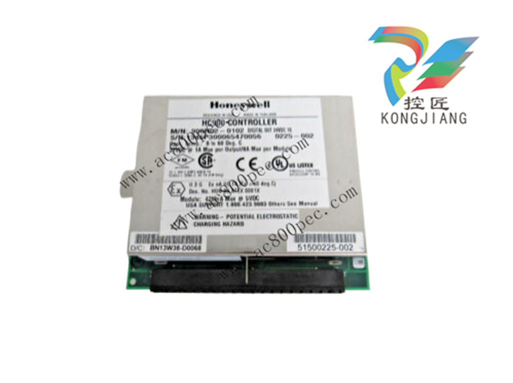
High Level Analog Input Module (900A16-xxxx)
The High-Level Analog Input module supports up to 16
user-configurable inputs on a per point basis for Voltage
or current. Point-to-point isolation and back-plane
isolation are provided. Modules perform analog to digital
conversion in synchronization with CPU control
execution, eliminating data interchange latency. All
analog input modules are processed in parallel,
eliminating scan time increases as modules are added.
A green blinking status LED on the module indicates
when the module is being scanned. An amber blinking
status LED when input channels are forced and a red
status LED when module diagnostics exist. A userselectable failsafe value is supported on a per channel
basis.
The module supports field calibration. Each of the inputs
has its own integrated 250-ohm shunt resistor which is
activated through DIP switches.
Requires Euro style 36-terminal terminal block.
Table 3 – High Level Analog Input Specifications
Inputs per module 16 (isolated)
Input types V, mA
Signal Source See Table 4 on next page for range types.
Input Impedance >1 megohm for volts and 250 ohms for mA inputs
Galvanic Input Isolation 400 VDC point to point, solid state switching; 1K VDC to logic.
Noise Rejection Series Mode >31dB
Common Mode >90dB at 120VAC
Over-range limit +/- 10% for linear ranges (volts).
Table 3 – High Level Analog Input Specifications
Accuracy Factory configured accuracy = ± 0.1 % of range.
Field calibration accuracy = ± 0.05 % of range
Reference conditions
Temperature = 25 °C ± 3 °C (77 °F ± 5 °F)
Humidity = 45 % to 55 % RH non-condensing
Line voltage = Nominal ± 1 %
Source resistance = 0 ohm
Series mode and common mode = 0 V
Frequency = Nominal ± 1 %
Temp. Effect on Accuracy ±0.01% of full scale per degree Celsius maximum
A/D Converter One per module
A/D Resolution 15 Bits
Update rate 100ms (Analog to Digital Converter per module)
Long term Stability 0.1% per year
Calibration Data is stored in non-volatile memory
Redundant Factory Calibration
Individual Channel Field Calibration
Diagnostics Monitoring of Factory Calibration, Field Calibration, 24 VDC supply, and
configuration.
Channel Configuration Data Stored in non-volatile memory.
Power supply loading 5V ; 75mA max
24V ; 50mA max
Table 4 - High Level Analog Input Reference Accuracy
Input Type Range Reference Accuracy
Milliamperes 4 to 20 mAdc 0.15% F.S. (mA)**
0 to 20 mAdc 0.15% F.S. (mA)**
**Tolerances for these input types include that of the internal Dropping Resistors.
Volts 0 to 1VDC 0.1% F.S. (mV)
0 to 2 VDC 0.1% F.S. (mV)
0 to 5 VDC 0.1% F.S. (mV)
0 to 10 VDC 0.1% F.S. (mV)
1 to 5 VDC 0.1% F.S. (mV)
-1 to 1 VDC 0.1% F.S. (mV)
-2 to 2 VDC 0.1% F.S. (mV)
-5 to 5 VDC 0.1% F.S. (mV)
-10 to 10 VDC 0.1% F.S. (mV)
Purchase history
| User name | Member Level | Quantity | Specification | Purchase Date |
|---|
Total 0 Record
Related products
Customer Reviews
Satisfaction :
5 Stars
No evaluation information


- other
- LTI Drives
- ADLINK
- Beckhoff
- Other Brands
- AMAT
- Iba
- PEPPERL+FUCHS
- Aerotech
- WATLOW
- MAN
- ADVANCED
- Abaco
- YOKOGAWA
- KOLLMORGEN
- MEGGITT
- kong-sberg
- METSO
- Motorola
- NI
- OEMAX
- RELIANCE
- scanlab
- schneider
- uniop
- Vibro-Meter
- Honeywell
- Rolls-Royce
- MOOG
- GE
- B&R
- Woodward
- Yaskawa
- xYCOM
- Siemens
- Emerson
- HIMA
- Bently
- ZYGO
- FOXBORO
- OMACO
- PROSOFT
- ENTERASYS
- TRICONEX
- Parker
- Lenze
- KEBA
- Alstom
- CTI
- ABB
- A-B
142

-
 ADLINK AmITX-SL-G Mini ITX Embedded Motherboard
 -
 ADLINK AmITX-AL-I ultra-thin Mini ITX industrial motherboard
 -
 ADLINK NuPRO-E315 Full length PICMG 1.3 Industrial SHB Single Board Computer
 -
 ADLINK NuPRO-842 Full length PICMG 1.0 PCI/ISA Industrial Single Board Computer
 -
 ADLINK NuPRO-900A PICMG 1.2 ePCI-X Dual Xeon Industrial System Motherboard (SHB)
 -
 ADLINK cPCI-6910 series 6U CompactPCI single board computer
 -
 ADLINK cPCI-6860A 6U CompactPCI dual core single board computer with cPCI-R6860A rear adapter board
 -
 ADLINK cPCI-8168 6U CompactPCI Eight Axis Motion Control Card
 -
 ADLINK NuPRO-E340 PICMG 1.3 Industrial SHB motherboard
 -
 ADLINK NuPRO-A40H Full length PICMG1.0 Industrial Single Board Computer (SBC)
 -
 ADLINK NuPRO-852 Full length PICMG1.0 Industrial Single Board Computer
 -
 ADLINK NuPRO-841 Full length Industrial SBC
 -
 ADLINK NuPRO-590/591/592 series Socket7 full-length industrial SBC
 -
 ADLINK MXE-5500 series fanless embedded industrial computer
 -
 ADLINK MXE-200/200i Fanless Embedded Machine
 -
 ADLINK cPCI-6770 series CompactPCI CPU board
 -
 ADLINK NuPRO-A301 standard PICMG 1.0 full-length industrial SBC single board computer
 -
 ADLINK NuPRO-965 PICMG 1.3 SHB Express Full length Industrial Motherboard
 -
 ADLINK NuPRO-935A Full length PICMG1.0 Industrial Single Board Computer
 -
 ADLINK NuPRO-865 Full length Single Board Computer
 -
 ADLINK NuPRO-840 DV/LV Full Length PICMG Industrial Single Board Computer
 -
 ADLINK NuPRO-770 series full-length industrial single board computer
 -
 ADLINK NuPRO-595 series half length Socket 7 industrial motherboard
 -
 ADLINK cPCI-6840 series 6U CompactPCI single board computer
 -
 Foxboro 43AP series pneumatic indicator controller (PSS 3-1B3 A)
 -
 ADLINK cPCI-3720 Series 3U Low Power CompactPCI Single Board Computer
 -
 ADLINK NuPRO-E47, PICMG 1.3 full-length industrial SHB system motherboard
 -
 ADLINK NuPRO-E43 PICMG 1.3 full-length system motherboard
 -
 ADLINK NuPRO-780 series full-length industrial CPU board
 -
 ADLINK cPCI-6965 series 6U CPCI single board computer
 -
 ADLINK USB/LPCI/LPCIe-3488A GPIB interface card
 -
 Rittal SK 3241.700 Blue e+Fan Filter Unit
 -
 ADLINK cPCI-8168 6U CompactPCI 8-Axis Motion Control Card
 -
 ADLINK PCIe PXIe-8638 PCIe to PXIe Bus Expansion Kit
 -
 ADLINK PCIe GIE7x series acquisition card
 -
 ADLINK PCIe-7396 96 96 channel TTL digital IO card
 -
 ADLINK PCI/MPC/PXI-8164 Three in One Motion Control Card
 -
 ADLINK PCI-8154 Four Axis Pulse Motion Control Card
 -
 ADLINK PCI-8134 Four Axis Servo/Stepper Motion Control Card
 -
 ADLINK NuPRO-E42 PICMG1.3 full-length SHB motherboard
 -
 ADLINK MXC-6600 series high-performance fanless extended industrial computer
 -
 ADLINK MXC-6000 series embedded industrial control computer
 -
 ADLINK MXC-2300 series fanless expandable embedded industrial computer
 -
 ADLINK MCM-204 Independent Ethernet DAQ User Manual
 -
 ADLINK MCM-100/102 Edge IoT Platform for Machine Condition Monitoring User’s Manual
 -
 ADLINK MXC-6400 series sixth generation Core Fanless Scalable Industrial Control Computer
 -
 ADLINK Matrix Full Series Fanless Embedded Industrial Control Computers
 -
 ADLINK GIE64+4-channel PoE Gigabit Vision Capture Card
 -
 Honeywell UMS Security System Troubleshooting Guide
 -
 Honeywell Expert Series-C I/O Module
 -
 ADLINK EOS-1200 Embedded Vision Host
 -
 ADLINK DLAP-5200 series high-performance fanless AI industrial computer
 -
 ADLINK DLAP-4000 series embedded industrial control computer
 -
 ADLINK Matrix MXC-2000 Series Fanless Industrial Control Computer Specification
 -
 ADLINK DAQ -/DAQE -/PXI-2000 Series Multi functional Synchronous Acquisition Card
 -
 ADLINK cPCI-6520 6U CompactPCI Single Board Computer
 -
 ADLINK CM1-86DX3 PC/104 Single Board Computer
 -
 Honeywell DC1000 series PID temperature controller
 -
 ALSTOM MiCOM C264 Modular Substation Controller
 -
 EMERSON AMS 2140 Mechanical Health Analyzer
 -
 ADLINK NuPRO-E320 PICMG1.3 Full length Industrial Motherboard
 -
 ADLINK NuPRO-800 Series Full length Industrial SBC User Manual
 -
 ADLINK NuPRO-598 Industrial Single Board Computer
 -
 ADLINK MXC-6300 Fanless Embedded Industrial Control Computer
 -
 ADLINK Express-BASE7 User Manual
 -
 ADLINK DLAP-211 Series Fanless Edge AI Platform Specification Manual
 -
 ADLINK PCI/LPCI/LPCIe/cPCI-723X series 32 channel isolated digital I/O card
 -
 ADLINK cPCI-6965 series 6U CompactPCI single board computer
 -
 ADLINK NuDAQ 7200 series high-speed digital I/O board
 -
 Linghua ADLINK DLAP Deep Learning Acceleration Platform Product Manual
 -
 DEIF TCM-2 thyristor control module
 -
 Installation Manual for DEIF MVR-200 Series Medium Voltage Protection Device
 -
 DEIF MDR-2 multifunctional differential relay
 -
 DEIF AOM-1 Analog Output Module
 -
 DEIF AGI 400 series industrial/marine touch screen
 -
 Installation Manual for DEIF BRW-1 Marine Wing Bridge Instrument
 -
 DEIF AGC200 Quick Start Guide
 -
 DEIF AGC Multi line 2 Generator Set ControllerProduct basic information
 -
 ABB SPA-ZC 400 Ethernet Gateway Installation and Debugging Manual
 -
 ABB REM 543/545 motor generator protection device
 -
 DEIF PPU 300 controller
 -
 DEIF Delomatic 4 Offshore/Ocean Platform Dedicated Generator Power Management System DM-4
 -
 DEIF Delomatic Modular Generator Set Integrated System
 -
 DEIF AGC-4 Mk II Generator Set Controller
 -
 DEIF AGC-4 diesel generator set integrated controller
 -
 DEIF Multi line 2 Series PPU Unit Power Management (PPM) Operation Manual
 -
 DEIF Multi line 2 V2.4X Installation Manual
 -
 Beckwith M-6280 Digital Capacitor Bank Controller
 -
 Beckwith M-3311 Transformer Protection Relay
 -
 Beckwith M-3311A Transformer Integrated Protection Device
 -
 Beckwith M-3310 Transformer Integrated Protection Device Specification
 -
 Beckwith M-0359 Syncrocloser Check Plus Application Guide for Synchronous Calibration Relay
 -
 Beckwith M-0293A On Load Tap changer Controller Application Guide
 -
 DEIF GPU-3 Synchronous/Asynchronous Generator Integrated Microcomputer Protection Controller
 -
 Installation Instructions for DEIF PPM-3
 -
 Beckwith M-3520 distributed power grid connected comprehensive protection device
 -
 Beckwith M-3430 generator comprehensive protection device
 -
 Beckwith M-2293B adapter panel
 -
 Beckwith M-2001C digital on load voltage regulator controller
 -
 Beckwith M-2001B Digital On Load Voltage Regulating Controller
 -
 Beckwith M-0388/M-0389 synchronous verification relay
 -
 Beckwith M-0193B synchronous closing device
 -
 Beckwith M-0115A Transformer Parallel Balancing Module
 -
 Beckwith M-0067E on load tap changer controller
 -
 Beckwith M-4272 Digital Motor Bus Switching System
 -
 Beckwith M-3311A Transformer Integrated Protection Device
 -
 Beckwith M-3425A Generator Integrated Protection Device Manual
 -
 Basler BE1-27/BE1-59/BE1-27/59 undervoltage/overvoltage relay
 -
 Basler AVC63-12/AVC125-10 excitation voltage regulator
 -
 Basler L301kc Color Three Line Array Camera Operation Manual
 -
 Basler CBS 212A Current Enhanced Excitation System
 -
 Basler BE3-25 synchronous check relay
 -
 Operation Manual for Basler BE1-32R/BE1-32O/U Direction Power Relay
 -
 Basler Electric PRS-250 Veri Sync Synchronous Relay
 -
 Basler Pilot Series Area Array Industrial Camera piA2400-17gc
 -
 Basler BE1-11g comprehensive protection device for generator
 -
 Basler VR63-4C/UL Analog Excitation Voltage Regulator
 -
 Basler BE1-DFPR distribution feeder protection relay
 -
 Basler CBS310/CBS320 current strong excitation system
 -
 Basler UFOV250A/UFOV260A Low Frequency Overvoltage Module
 -
 Basler MVC104/MVC108/MVC232 manual voltage control device
 -
 Basler XR2002/XR2002F PMG excitation regulator
 -
 Basler DECS-400 Digital Excitation Control System
 -
 Basler DGC-2020 Digital Generator Set Controller
 -
 Basler MVC-300 Electronic Manual Excitation Controller
 -
 Basler MVC-104/MVC-108/MVC-232 manual excitation controller
 -
 Basler SSR32-12/SSR63-12/SSR125-12 Static Excitation Voltage Regulator
 -
 Basler SR4A/SR8A Analog Excitation Voltage Regulator

K-JIANG

Add: Jimei North Road, Jimei District, Xiamen, Fujian, China
Tell:+86-15305925923