

K-WANG
+086-15305925923
Service expert in industrial control field!


Product
Article
NameDescriptionContent
Adequate Inventory, Timely Service
pursuit of excellence


Ship control system
Equipment control system
Power monitoring system
Brand
Product parameters
- Telephone:+86-15305925923
- contacts:Mr.Wang
- Email:wang@kongjiangauto.com
Description
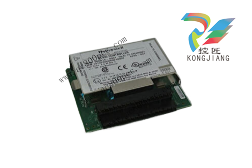
The Honeywell ControlEdge HC900 Controller is an
advanced loop and logic controller offering a modular design
sized to satisfy the control and data acquisition needs of a
wide range of process equipment.
Honeywell Redundant Controller C75 CPU 900C75-0360-00
ControlEdge HC900 IO Modules
Specifications
51-52-03-41, May 2019
Overview
The Honeywell ControlEdge HC900 Controller is an
advanced loop and logic controller offering a modular design
sized to satisfy the control and data acquisition needs of a
wide range of process equipment.
I/O Modules
The following I/O modules are available to create a custom
control solution.
16 Channel Universal IO Module Galavanically isolated
Input/Output to chassis (p.27)
8-point universal analog input modules: Galvanic
isolation point to chassis inputs may be mixed on a
module and may include multiple thermocouple types,
RTDs, ohms, voltage or mill voltage types – all easily
assigned using the Process Control Designer
configuration tool. High point-to-point galvanic isolation
simplifies installation and saves the expense of external
isolation hardware (p.6).
16-point high level analog input module: each point is
configurable for V or mA. Galvanically isolated point to
chassis. Galvanically isolated point to point (p.10). 250-
ohm shunt resistors can be added per channel.
4-point galvanically isolated analog output module.
Galvanically isolated point to chassis supports from 0 to
20mA each (p.12).
8-point analog output, galvanically isolated in 2 groups
of 4 points. Galvanically isolated point to chassis.
Supports from 0 to 20mA each (p.13).
16-point analog output, galvanically isolated in 4 groups
of 4 points. Galvanically isolated point to chassis.
Supports from 0 to 20mA each (p.14).
16-point digital input modules: Contact closure type, DC
Voltage, AC Voltage and AC/DC voltage types (p.15).
Galvanically isolated in groups of 8 channel to chassis
32-point digital input module: DC voltage. Galvanically
isolated point to chassis. Galvanically isolated in 2
groups of 16 points (p.1915).
8-point AC or 16-point DC digital output modules
(sinking type). Galvanically isolated point to chassis.
Galvanically isolated in 2 groups of 8 points (p.18).
32-point digital output: DC voltage (sourcing type).
Galvanically isolated point to chassis. Galvanically
isolated in 2 groups of 16 points (p.23).
8-point relay output module: four form C type and four
form A type relays. Galvanically isolated point to
chassis. Galvanically isolated relay to relay (p.20).
4 channel Pulse/Frequency/Quadrature I/O module.
Galvanically isolated point to chassis (p.24).
Insert and Removal of I/O under Power
For ease of maintenance, the ControlEdge HC900 controller
supports removing and inserting I/O modules from the
module rack without removing power from the controller.
Each module is sensed for validity by the controller
and auto-configured on insertion.
Other Modules
In addition to I/O, the following modules are available.
Scanner 1 module, single port (p.31)
Scanner 2 Module, dual port (p.32)
Universal AC Power Supply, 60W (p.4)
Power Supply 24VDC, 60W (p.4)
Redundant Switch Module (p.33)
Power Status Module (p.33)
Failsafe
All ControlEdge 900 Platform I/O modules support a user
specified failsafe value (analog) or state (digital) that the
module outputs or inputs will assume if communication
between the controller and the module is interrupted. Output
modules are also disabled if the controller fails to start.
Module diagnostics are not initiated if the control strategy
does not call for the inputs or outputs on the modules to
execute.
Failsafe is restricted to de-energize in safety applications
Remote Terminal Panels
Optional DIN rail mounted Remote Terminal Panels (RTPs) are available for use with pre-wired cables to reduce installation
time and labor expense. Three types of RTPs are available: analog inputs, relay outputs, and other I/O modules. Three cable
lengths are also available to match hardware to installation variations. Analog inputs RTPs include transmitter shunt resistors
and transmitter power terminals with individual circuit fuses. The Relay Output RTP includes a fuse and power disconnect
switch for each output. All the three types of RTP panels also switch power to allow module removal and installation under
controller power. See page 34.
Terminal Blocks
20-screw Barrier style and Euro style terminal blocks are available for use with all ControlEdge HC900 I/O Modules.
Red terminal blocks are used for high voltage connections for added safety while black terminal blocks are used for low
voltage connections. A 36-terminal Euro style block is available with the 16 AI, the 8 and 16 AO as well as the 32 DC DI and
32 DC DO module types. See page 27.
Specifications for modules
I/O Module Attributes
Remove & Insert under power Standard. Modules are automatically sensed and configured on insertion. Field power
shall be disconnected before removing field terminal blocks.
LED Channel State indicators Via light pipes at front of module, one state LED for each digital I/O point – green
indicates ON, logic side
LED Module Status indicator Via light pipe, one per module, tri-color to represent module status, Green = OK, Red
= Fault (# of flashes indicates fault), Amber = Override (Force)
I/O Labels Color-coded, on module door, removable, with write-on area to label I/O
Processor Micro-controller per module for parallel processing
Terminal Boards 20 screw: Barrier or Euro style, tin-plated or gold-plated (for DC connections)
36 screw: Euro style gold plated (Required with certain higher capacity modules)
Keying Hardware keying matches each module to its terminal block with its field wiring.
Environmental and Vibration Specifications
Mounting
Standard 35mm wide DIN Rail Provides connection of field wiring to controller I/O within an enclosure only.
Dimensions 4.38” (111.1 mm) x 3.70” (94.0mm) x 2.60” (66.0mm) (L x W x H)
Vibration
Amplitude
Acceleration
Vibration
5Hz to 15.77Hz, 2.03mm (0.08”) amplitude (peak to peak)
15.77 to 250Hz, 1.0-g
Sweeping, at rate of .33 octave/min.
Tray material
Tray and end caps
Flammability
Polyvinyl Chloride (PVC)
UL94-V0
Environmental
Temperature
Relative Humidity
Harsh Environment **
ROHS**
** Except PSU module
Operating: 0 deg. C (32F) to 60 deg. C (140F)
Storage: -40 deg. C (140F) to 70 deg. C (158F)
Operating: 10% to 90% Non-condensing
Storage: 5% to 95% Non-condensing
All the modules including CPU, Scanner, PSU, RTP, Backplane, RSM/PSM, and
Backplanes have conformal coating that is suitable for operation in G3 level of harsh
environment.
Entire system is compliant to RoHS 2 directive
Purchase history
| User name | Member Level | Quantity | Specification | Purchase Date |
|---|
Total 0 Record
Related products

Customer Reviews
Satisfaction :
5 Stars
No evaluation information


- LTI Drives
- other
- ADLINK
- Beckhoff
- Shinkawa
- Other Brands
- AMAT
- Iba
- PEPPERL+FUCHS
- Aerotech
- WATLOW
- MAN
- ADVANCED
- Abaco
- YOKOGAWA
- KOLLMORGEN
- MEGGITT
- kong-sberg
- METSO
- Motorola
- NI
- OEMAX
- RELIANCE
- scanlab
- schneider
- uniop
- Vibro-Meter
- Honeywell
- Rolls-Royce
- MOOG
- GE
- B&R
- Woodward
- Yaskawa
- xYCOM
- Siemens
- Emerson
- HIMA
- Bently
- ZYGO
- FOXBORO
- OMACO
- PROSOFT
- ENTERASYS
- TRICONEX
- Parker
- Lenze
- KEBA
- Alstom
- CTI
- ABB
- A-B
142

-
 SIGMATEK TAE 1941 Touch Display Unit
 -
 SIGMATEK TAE 151 Touch Display Unit
 -
 SIGMATEK AKM series servo motor
 -
 SIGMATEK S-DIAS Control System
 -
 SIGMATEK Human Machine Interface (HMI)
 -
 SIGMATEK DIAS Drive 310-23 servo amplifier
 -
 SIGMATEK CCP 521 C-DIAS processor module
 -
 MEGMEET L6 series electric drive
 -
 Sysmex XN-1000/XN-2000 Hematology Analyzer
 -
 Sysmex XN-L series (XN-530/XN-430/XN-330) fully automatic blood cell analyzer
 -
 Sysmex XN-9000 Series Fully Automated Blood Analysis Pipeline
 -
 LTI‑Motion ServoOne Field Bus Systems PROFIBUS and PROFINET
 -
 Micro Innovation MICRO PANEL GF1 Color Touch Human Computer Interface
 -
 Micro Innovation WINbloc Distributed Remote I/O System
 -
 Micro Innovation MICRO PANEL GS-2 Industrial Touch Visualization Operation Panel (HMI)
 -
 LTi LST/LSH series synchronous servo motor
 -
 LTi CDE/CDB3000 positioning controller
 -
 ENOTEC SILOTEC ® Installation and Operation Instructions for 8000 Silo Monitoring O ₂/CO ₑ Analyzer System
 -
 ENOTEC ENSITU ® 7000 Compact Oxygen Transmitter Probe
 -
 ENOTEC COMTEC ® Installation and Operation Instructions for 6000 ATEX GasEx Explosion proof O ₂/COE Analyzer System
 -
 ENOTEC Integrated Products
 -
 ENOTEC OXITEC ® 500E Extraction Oxygen Analyzer
 -
 KUKA KR CS Box-2 Compact Controller for Four Axis SCARA Robot
 -
 KUKA KR C5 slim-2 Robot Controller
 -
 KUKA KR C5 micro With KUKA System Software (KSS/VSS) Assembly Instructions
 -
 KUKA KR C5 micro controller
 -
 KUKA KR C5 Controller Assembly Instructions
 -
 KUKA KR C5 compactcab and KR C5 small-size cab cabinets
 -
 KUKA KR C4 smallsize-2 small robot control cabinet
 -
 KUKA KR C4 Midsize/KR C4 Midsize CK Assembly Manual
 -
 ENOTEC ® Installation and Operation Instructions for 5000/5000+Oxygen Analyzer System
 -
 KUKA KR C4 extended; KR C4 extended CK Assembly Instructions Assembly Manual
 -
 Assembly/Installation Manual for KUKA KR C4 Compact Control Cabinet
 -
 KUKA Sunrise Cabinet Med Medical Collaborative Robot Special Control Cabinet
 -
 KUKA Sunrise Cabinet Next Generation Small Control Cabinet
 -
 KUKA KR C4 Smallsize-2 family's smallest control cabinet
 -
 KUKA KR C4 midsize; KR C4 midsize CK medium-sized control cabinet
 -
 KUKA KR C4 extended is a high-power multi axis control cabinet
 -
 General installation and operation instructions for KUKA KR C4 and KR C4 CK controllers
 -
 KUKA KR C4 compact controller operation instructions
 -
 Installation and Operation Instructions for KUKA Robot Arm
 -
 KUKA TITAN-2 Ultra Ground Overloading Six Axis Robot
 -
 Assembly instructions for KUKA KR SCARA-2 CS series robotic arm body
 -
 KUKA MA KR SCARA X Installation Guide
 -
 KUKA KR FORTEC-2 Ultra Heavy duty Ground Six Axis Robot Mechanical Assembly Manual
 -
 KUKA KR FORTEC-2 new generation heavy-duty ground six axis robot
 -
 KUKA Robots KR 1000 titan; KR 1000 L750 titan With F Variants Assembly Instructions
 -
 KUKA KR 600 FORTEC heavy-duty six axis ground mounted industrial robot
 -
 KUKA KR 500 MT FORTEC Heavy duty Six Axis Industrial Robot
 -
 KUKA KR 360 FORTEC Heavy duty Six Axis Industrial Robot
 -
 KUKA Sunrise Cabinet Med Medical Edition Robot Controller User Manual
 -
 KUKA Robots KR SCARA HO Assembly Instructions
 -
 KUKA Robots KR QUANTEC-2 PA Assembly Instructions
 -
 KUKA Robots KR QUANTEC-2 K and KR QUANTEC-2 P With K-F and P-C Variants Assembly Instructions
 -
 KUKA Robots KR QUANTEC-2 HO Assembly Instructions
 -
 KUKA Robots KR QUANTEC-2 HC Assembly Instructions
 -
 KUKA KR QUANTEC-2 series heavy-duty ground mounted six axis industrial robot
 -
 KUKA KR QUANTEC PA series heavy-duty palletizing robot
 -
 KUKA KR IONTEC-2 series six axis industrial robot
 -
 KUKA KR IONTEC ultra series six axis heavy-duty industrial robot
 -
 KUKA KR IONTEC HO Robot Assembly Manual
 -
 KUKA Robots KR CYBERTECH-3 HW Assembly Instructions
 -
 KUKA Robots KR CYBERTECH-3 Assembly Instructions
 -
 KUKA Robots KR CYBERTECH-2 arc Assembly Instructions
 -
 KUKA Robots KR CYBERTECH nano-2 Assembly Instructions
 -
 KUKA KR CYBERTECH CR HO (KR 20 R1810-HO) assembly instructions
 -
 KUKA Robots KR CYBERTECH With F variant Assembly Instructions
 -
 KUKA KR CYBERTECH CR (KR 20 R1810-CR) Clean Room (CR) Version 6-Axis Industrial Robot
 -
 KUKA KR AGILUS-3 ultra series small six axis serial robot
 -
 KUKA KR 300 R2700-2 C-F Cast Ceiling Mounted 6-Axis Heavy duty Industrial Robot
 -
 KUKA KR 20 R1820-2 E Six Axis Industrial Robot
 -
 Assembly instructions for KUKA KR AGILUS-3 small six axis robot
 -
 KUKA KR AGILUS-2 New Generation Small Six Axis Robot
 -
 KUKA KR 1000 1300 titan PA; KR 1000 L950 titan PA With F Variants Assembly Instructions
 -
 KUKA KR 700 PA/KR 700 PA Arctic Installation Guide
 -
 KUKA KR 18 R1450-3 PP six axis ground mounted industrial robot
 -
 KUKA 12 SCARA Series 4-axis SCARA Horizontal Joint Robot
 -
 KUKA KR 4 R600 Small Six Axis Industrial Robot
 -
 Installation Guide for KUKA KR 3 R540 Small 6-Axis Industrial Robot
 -
 KUKA LBR iiwa CR Clean 7-Axis Lightweight Collaborative Robot
 -
 KUKA KR AGILUS sixx series six axis industrial robot operation instructions
 -
 KUKA 4-axis heavy-duty SCARA horizontal multi joint robot KR 60 R1200 Z400 CS
 -
 KUKA KR 23 SCARA-2 CS SCARA Horizontal Multi Joint Robot
 -
 KUKA KR 20 SCARA CS Robot Assembly Instructions
 -
 KUKA KR 15 DELTA-2 Assembly Manual
 -
 KUKA KR 13 SCARA-2 CS Assembly Manual
 -
 KUKA KR 3 D1200 (Standard Delta Robot) Assembly Instructions
 -
 KUKA KR 3 D1200 HM Assembly Manual
 -
 KUKA LBR Med 7 R800, LBR Med 14 R820 Medical Edition Robot
 -
 KUKA Robots LBR iiwa 7 R800, LBR iiwa 14 R820 Operating instructions
 -
 KUKA LBR iiwa CR (Clean Room Version Robot) Operating Instructions
 -
 Lauer PCStopline series text operation panel
 -
 KUKA LBR iisy (MA_LBR_iisy V5) assembly manual
 -
 KUKA LBR iisy 3 R760 Assembly Manual
 -
 KUKA LBR iico Collaborative Robot Assembly Manual
 -
 Lauer LCAstarline (LCA300/LCA320/LCA325) Text Display Screen
 -
 Lauer PCS950/PCS950c/PCS950e operation console
 -
 Lauer EPC Series Industrial Embedded Human Computer Integrated PC User Guide
 -
 Bonfiglioli Precision Planetary Gearbox TIR-STD ENG R07
 -
 Bonfiglioli ACT/ACU Cold Plate Inverter Installation Instructions
 -
 Bonfiglioli EM-RES-02 Expansion Module
 -
 Bonfiglioli EM-RES-01 Expansion Module
 -
 Bonfiglioli EM-IO-04 Expansion Module
 -
 Bonfiglioli EM-IO-03 Expansion Module
 -
 Bonfiglioli EM-IO-02 Expansion Module
 -
 Bonfiglioli Vectron EM-IO-01 Expansion Module
 -
 Bonfiglioli F series gearbox
 -
 Installation, operation, maintenance, and spare parts of Bonfiglioli HF series reducers
 -
 Installation, Operation, and Maintenance of Bonfiglioli 300-300M Series ATEX Reducer
 -
 Bonfiglioli R3 series planetary gearbox
 -
 Bonfiglioli C series inline helical gear explosion-proof reducer
 -
 Bonfiglioli EM-ENC-05 Expansion Module
 -
 Bonfiglioli EM-ENC-04 Expansion Module
 -
 Bonfiglioli EM-ENC-03 Expansion Module
 -
 Bonfiglioli EM-ENC-02 Expansion Module
 -
 Bonfiglioli CM-CAN CANopen communication module
 -
 Bonfiglioli EM-SYS System Bus Expansion Module
 -
 Bonfiglioli CM-PDP Profibus DP Communication Module
 -
 Bonfiglioli CM-232/CM-485/CM-485T Modbus Communication Manual
 -
 Bonfiglioli BMS series precision planetary servo reduction motor
 -
 Bonfiglioli ACTION series ACT210 (230V), ACT410 (400V) frequency converter operation manual
 -
 Bonfiglioli ACT series frequency converter
 -
 Bonfiglioli HDP/HDO series gear unit IOM installation, operation and maintenance instructions
 -
 Installation, operation, and maintenance of Bonfiglioli 300-300M series reducers
 -
 Bonfiglioli 300M Modular planetary gearboxe
 -
 Bonfiglioli 3/H series heavy-duty modular gearbox
 -
 Bonfiglioli KRG-KCG-KSD hydraulic coupling
 -
 Bonfiglioli Vectron BTD-BCR servo motor

K-JIANG

Add: Jimei North Road, Jimei District, Xiamen, Fujian, China
Tell:+86-15305925923