

K-WANG
+086-15305925923
Service expert in industrial control field!


Product
Article
NameDescriptionContent
Adequate Inventory, Timely Service
pursuit of excellence


Ship control system
Equipment control system
Power monitoring system
Brand
Product parameters
- Telephone:+86-15305925923
- contacts:Mr.Wang
- Email:wang@kongjiangauto.com
Description
RX3i features a wide range of Specialty Modules to meet all of your application needs.
From temperature controls, high-speed counters, I/O processors, coprocessors, to PID
auto-tuning modules, these Specialty Modules are designed to meet the demand for
versatile industrial solutions.
GE IC695CMM002 Co-Processor and Serial Communications Modules
PACSystems RX3i Programmable Controllers
RX3i features a wide range of Specialty Modules to meet all of your application needs.
From temperature controls, high-speed counters, I/O processors, coprocessors, to PID
auto-tuning modules, these Specialty Modules are designed to meet the demand for
versatile industrial solutions.
Co-Processor and Serial Communications Modules
IC695CMM002 IC695CMM004 IC695PRS015 HE693ASC900
Product Name
Two Port Serial Module Four Port Serial Module Pressure Transducer Module
supporting Honeywell LG1237
Smart Sensors
Horner ASCII Basic Module
Lifecycle Status Active Active Active Active
Module Type
Serial Communications
2 Isolated Serial Ports
Serial Communications
4 Isolated Serial Ports
Serial Communications Serial Communications
4 Isolated Serial Ports
ASCII Basic Co-Processor
Backplane Support Universal Backplane Only.
Uses PCI Bus
Universal Backplane Only.
Uses PCI Bus
Universal Backplane Only.
Uses PCI Bus.
No Backplane Restrictions
Number of Slots Module
Occupies on Backplane 1 1 1 1
Protocols Supported
Serial Read/Write Modbus
Master/Slave DNP 3.0 Master/
Slave CCM Slave and
Custom Protocols
Serial Read/Write Modbus
Master/Slave DNP 3.0 Master/
Slave CCM Slave and
Custom Protocols
Pressure Transducer Honeywell
LG1237 Smart Pressure
Transducer sensors
(Up to 15 sensors)
N/A
Programming Languages None required. Communications
set up in Proficy Machine Edition
None required. Communication
set up in Proficy Machine Edition
BASIC
Program Storage FLASH FLASH FLASH EEPROM
Communication Ports (2) Isolated RS-232 or RS-485/422 (4) Isolated RS-232 or RS-485/422 (1) RS-485 RS-232, RS-232/485
Network Data Rate
Selectable Baud Rates: 1200,
2400, 4800, 9600, 19.2K, 38.4K,
57.6K, 115.2K
Selectable Baud Rates: 1200,
2400, 4800, 9600, 19.2K, 38.4K,
57.6K, 115.2K
375K baud N/A
Internal Power Used 0.7 Amps maximum @ 3.3 VDC
0.115 Amps maximum @ 5 VDC
0.7 Amps maximum @ 3.3 VDC
0.150 Amps maximum @ 5 VDC
0.7 Amps maximum @ 3.3 VDC
0.115 Amps maximum @ 5.0 VDC
375 mA @ 5 VDC
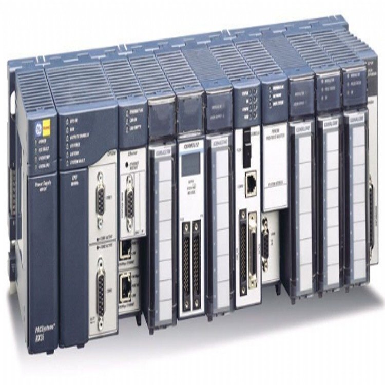
Programmable Controllers
The High Speed Counters can be used for a wide range of applications. The following types are supported.
Type A - Up or Down-Independent Pulse-4 counters
Type B - Both Directions-A QUAD B Encoder Inputs-2 Counters
Type C - Difference Between 2 changing values-A QUAD B Encoder Inputs -1 Counter
Type D - provides homing capability with count inputs and a Home Marker input. In A quad B mode, the counter detects quadrature errors
Type E - Pre-defined Counter Type that occupies two of the module’s internal counters, primarily a down counter, but can handle up
counts to account for A quad B jitter
Type E counter counts down to zero, it uses a second counter block to turn on a dedicated output for a configurable time. Type E can be
set up for sequenced strobing, which links all four strobes on so that they are all triggered by strobe input 1
Type Z - Two regular Clock inputs, a software controlled Preload and a special Clock Input Z. The Z input triggers a store of the
Accumulator value to the Strobe 1 register. After the store, the counter can optionally reset the Accumulator to 0. It can then either restart
immediately or after wait until the Clock Input Z is no longer set User-Defined Counter Type - Create a customized counter type by select ing High-Speed Counter features that are suited to the application. This counter type provides a Clear input that can be used to immedi ately reset the Accumulator to the starting value.
Motion Control (High Speed Counting)
IC694APU300 IC695HSC304 IC695HSC308 IC694APU305
Product Name PACSystems RX3i
High Speed Counter
PACSystems RX3i
High Speed Counter
PACSystems RX3i
High Speed Counter
PACSystems RX3i
I/O Processor Module
Lifecycle Status Active (Enhancement Mode
Available June 2012) Active Active Active
Module Type
High Speed Counter (*Enhanced
Mode support: 1Mhz input frequency,
expanded filtering, single ended,
differential encoders, 32 bit counters,
Z counter and windowing)
High Speed I/O Processing
(4 counters) Module supports High
Speed Counting, PLS (Programmable
Limit Switch), Camming, Input
Interrupts and Pulse Width Timing
High Speed I/O Processing
(8 counters) Module supports High
Speed Counting, PLS (Programmable
Limit Switch), Camming, Input
Interrupts and Pulse Width Timing
I/O Processor Module
Backplane Support No Backplane Restrictions Universal Backplane Only.
Uses PCI Bus.
Universal Backplane Only.
Uses PCI Bus.
No Backplane Restrictions
Number of Slots Module
Occupies on Backplane 1 1 1 1
Input/Output Type Positive Logic Positive Logic Positive Logic N/A
Off State Leakage Current 10 µA per point 200 µA 200 µA 10 µA per point
Output Protection 3 Amp Fuse for all points, Enhanced
Module will have ESCP protection
1.5 A maximum per channel, 10.5 A
maximum per module
1.5 A maximum per channel, 10.5 A
maximum per module
5 A Fuse for all points
Counter Operation Type A, Type B, and Type C
Enhanced Mode Type Z
Type A, Type B, Type C, Type D, Type
E, Type Z and User-Defined Counter
Type A, Type B, Type C, Type D, Type
E, Type Z and User-Defined Counter
Gray Code Encoder or A Quad B
Encoder every 500 microseconds
CPU Interrupt Support No Yes Yes N/A
PLS and Camming Support No Yes Yes N/A
Input Filters (Selectable)
High Frequency Filter - 2.5 µs;
Low Frequency Filter - 12.5 ms;
*Enhancement Mode: 5 ms, 500 µs,
10 µs and no filter
30 Hz, 5 KHz, 50 KHz, 500 KHz, 5 MHz 30 Hz, 5 KHz, 50 KHz, 500 KHz, 5 MHz N/A
Count Rate
High Frequency - 80 kHz;
Low Frequency - 20 Hz;
*Enhanced Mode Up to 1MHz with
2MHz internal Oscillator
High Frequency 1.5 MHz
(internal 2 MHz oscillator)
High Frequency 1.5 MHz
(internal 2 MHz oscillator)
30 kHz (Absolute Encoder) 200 kHz
(A Quad B Encoder)
Counter Range
-65,535 to 65,535 ; *Enhanced Mode
-2,147,483,648 to 2,147,483,647 with
roll over detection
-2,147,483,648 to 2,147,483,648 -2,147,483,648 to 2,147,483,648 N/A
Selectable On/Off
Output Presets
Each Counter has 2 present points,
On and Off; *Enhanced Mode up to 4
configurable outputs
Each Counter has 4 present points,
On and Off
Each Counter has 4 present points,
On and Off
N/A
Counters per Timebase
Each counter stores the number
of counts that have occurred in a
specified time. A timebase value
measurement from 1 ms to 65535
ms is configurable.
A Timebase from 100 nanoseconds
to 429,496 milliseconds can be
selected for each counter.
A Timebase from 100 nanoseconds
to 429,496 milliseconds can be
selected for each counter.
N/A
Strobe Register
Each counter has one or more strobe
registers that capture the current
accumulator value when a strobe
input transition in the direction
selected during the last
configuration of the module.
Each counter has one or more strobe
registers that capture the current
accumulator value when a strobe
input transition in the direction
selected during the last
configuration of the module.
Each counter has one or more strobe
registers that capture the current
accumulator value when a strobe
input transition in the direction
selected during the last
configuration of the module.
N/A
Local Fast Inputs
(12) 5 VDC or 10 to 30 VDC (8 inputs) 5 VDC nominal: 4.7 VDC
to 5.5 VDC 12 to 24 VDC nominal:
10 VDC to 26.4 VDC Inputs are
mapped to any counter or to the
controller as interrupts.
(16 inputs) 5 VDC nominal: 4.7 VDC
to 5.5 VDC 12 to 24 VDC nominal:
10 VDC to 26.4 VDC Inputs are
mapped to any counter or to the
controller as interrupts.
(12) 8.0 VDC (non-VTTL),
1.5 VDC (TTL)
Local Fast Outputs
(4) 10 to 30 VDC @ 500 mA maximum
4.75 to 6 VDC @ 20 mA maximum
(7 outputs) 4.7 to 40 VDC 1.5 A
maximum per channel, 10.5 A
maximum per module Outputs can
be used by the counters or as
standard outputs from the controller.
(14 outputs) 4.7 to 40 VDC 1.5 A
maximum per channel, 10.5 A
maximum per module Outputs can
be used by the counters or as
standard outputs from the controller.
Continuous Output Current
(10°V30 VDC supply) 1.0 A
(each output 1-V4) 0.5 A
(each output 5-V8)
Connector Type Terminal Block (20 screws),
included with module.
IC694TBBx32 or IC694TBSx32.
Sold Separately.
IC694TBBx32 or IC694TBSx32.
Sold Separately.
Terminal Block (20 screws),
included with module.
Internal Power Used 250 mA @ 5 VDC 64 mA maximum @ 5 V;
457 mA maximum @ 3.3 V
94 mA maximum @ 5 V;
561 mA maximum @ 3.3 V
360 mA @ 5 VDC
Purchase history
| User name | Member Level | Quantity | Specification | Purchase Date |
|---|
Total 0 Record
Related products
Customer Reviews
Satisfaction :
5 Stars
No evaluation information


- LTI Drives
- other
- ADLINK
- Beckhoff
- Shinkawa
- Other Brands
- AMAT
- Iba
- PEPPERL+FUCHS
- Aerotech
- WATLOW
- MAN
- ADVANCED
- Abaco
- YOKOGAWA
- KOLLMORGEN
- MEGGITT
- kong-sberg
- METSO
- Motorola
- NI
- OEMAX
- RELIANCE
- scanlab
- schneider
- uniop
- Vibro-Meter
- Honeywell
- Rolls-Royce
- MOOG
- GE
- B&R
- Woodward
- Yaskawa
- xYCOM
- Siemens
- Emerson
- HIMA
- Bently
- ZYGO
- FOXBORO
- OMACO
- PROSOFT
- ENTERASYS
- TRICONEX
- Parker
- Lenze
- KEBA
- Alstom
- CTI
- ABB
- A-B
145

-
 SIGMATEK TAE 1941 Touch Display Unit
 -
 SIGMATEK TAE 151 Touch Display Unit
 -
 SIGMATEK AKM series servo motor
 -
 SIGMATEK S-DIAS Control System
 -
 SIGMATEK Human Machine Interface (HMI)
 -
 SIGMATEK DIAS Drive 310-23 servo amplifier
 -
 SIGMATEK CCP 521 C-DIAS processor module
 -
 MEGMEET L6 series electric drive
 -
 Sysmex XN-1000/XN-2000 Hematology Analyzer
 -
 Sysmex XN-L series (XN-530/XN-430/XN-330) fully automatic blood cell analyzer
 -
 Sysmex XN-9000 Series Fully Automated Blood Analysis Pipeline
 -
 LTI‑Motion ServoOne Field Bus Systems PROFIBUS and PROFINET
 -
 Micro Innovation MICRO PANEL GF1 Color Touch Human Computer Interface
 -
 Micro Innovation WINbloc Distributed Remote I/O System
 -
 Micro Innovation MICRO PANEL GS-2 Industrial Touch Visualization Operation Panel (HMI)
 -
 LTi LST/LSH series synchronous servo motor
 -
 LTi CDE/CDB3000 positioning controller
 -
 ENOTEC SILOTEC ® Installation and Operation Instructions for 8000 Silo Monitoring O ₂/CO ₑ Analyzer System
 -
 ENOTEC ENSITU ® 7000 Compact Oxygen Transmitter Probe
 -
 ENOTEC COMTEC ® Installation and Operation Instructions for 6000 ATEX GasEx Explosion proof O ₂/COE Analyzer System
 -
 ENOTEC Integrated Products
 -
 ENOTEC OXITEC ® 500E Extraction Oxygen Analyzer
 -
 KUKA KR CS Box-2 Compact Controller for Four Axis SCARA Robot
 -
 KUKA KR C5 slim-2 Robot Controller
 -
 KUKA KR C5 micro With KUKA System Software (KSS/VSS) Assembly Instructions
 -
 KUKA KR C5 micro controller
 -
 KUKA KR C5 Controller Assembly Instructions
 -
 KUKA KR C5 compactcab and KR C5 small-size cab cabinets
 -
 KUKA KR C4 smallsize-2 small robot control cabinet
 -
 KUKA KR C4 Midsize/KR C4 Midsize CK Assembly Manual
 -
 ENOTEC ® Installation and Operation Instructions for 5000/5000+Oxygen Analyzer System
 -
 KUKA KR C4 extended; KR C4 extended CK Assembly Instructions Assembly Manual
 -
 Assembly/Installation Manual for KUKA KR C4 Compact Control Cabinet
 -
 KUKA Sunrise Cabinet Med Medical Collaborative Robot Special Control Cabinet
 -
 KUKA Sunrise Cabinet Next Generation Small Control Cabinet
 -
 KUKA KR C4 Smallsize-2 family's smallest control cabinet
 -
 KUKA KR C4 midsize; KR C4 midsize CK medium-sized control cabinet
 -
 KUKA KR C4 extended is a high-power multi axis control cabinet
 -
 General installation and operation instructions for KUKA KR C4 and KR C4 CK controllers
 -
 KUKA KR C4 compact controller operation instructions
 -
 Installation and Operation Instructions for KUKA Robot Arm
 -
 KUKA TITAN-2 Ultra Ground Overloading Six Axis Robot
 -
 Assembly instructions for KUKA KR SCARA-2 CS series robotic arm body
 -
 KUKA MA KR SCARA X Installation Guide
 -
 KUKA KR FORTEC-2 Ultra Heavy duty Ground Six Axis Robot Mechanical Assembly Manual
 -
 KUKA KR FORTEC-2 new generation heavy-duty ground six axis robot
 -
 KUKA Robots KR 1000 titan; KR 1000 L750 titan With F Variants Assembly Instructions
 -
 KUKA KR 600 FORTEC heavy-duty six axis ground mounted industrial robot
 -
 KUKA KR 500 MT FORTEC Heavy duty Six Axis Industrial Robot
 -
 KUKA KR 360 FORTEC Heavy duty Six Axis Industrial Robot
 -
 KUKA Sunrise Cabinet Med Medical Edition Robot Controller User Manual
 -
 KUKA Robots KR SCARA HO Assembly Instructions
 -
 KUKA Robots KR QUANTEC-2 PA Assembly Instructions
 -
 KUKA Robots KR QUANTEC-2 K and KR QUANTEC-2 P With K-F and P-C Variants Assembly Instructions
 -
 KUKA Robots KR QUANTEC-2 HO Assembly Instructions
 -
 KUKA Robots KR QUANTEC-2 HC Assembly Instructions
 -
 KUKA KR QUANTEC-2 series heavy-duty ground mounted six axis industrial robot
 -
 KUKA KR QUANTEC PA series heavy-duty palletizing robot
 -
 KUKA KR IONTEC-2 series six axis industrial robot
 -
 KUKA KR IONTEC ultra series six axis heavy-duty industrial robot
 -
 KUKA KR IONTEC HO Robot Assembly Manual
 -
 KUKA Robots KR CYBERTECH-3 HW Assembly Instructions
 -
 KUKA Robots KR CYBERTECH-3 Assembly Instructions
 -
 KUKA Robots KR CYBERTECH-2 arc Assembly Instructions
 -
 KUKA Robots KR CYBERTECH nano-2 Assembly Instructions
 -
 KUKA KR CYBERTECH CR HO (KR 20 R1810-HO) assembly instructions
 -
 KUKA Robots KR CYBERTECH With F variant Assembly Instructions
 -
 KUKA KR CYBERTECH CR (KR 20 R1810-CR) Clean Room (CR) Version 6-Axis Industrial Robot
 -
 KUKA KR AGILUS-3 ultra series small six axis serial robot
 -
 KUKA KR 300 R2700-2 C-F Cast Ceiling Mounted 6-Axis Heavy duty Industrial Robot
 -
 KUKA KR 20 R1820-2 E Six Axis Industrial Robot
 -
 Assembly instructions for KUKA KR AGILUS-3 small six axis robot
 -
 KUKA KR AGILUS-2 New Generation Small Six Axis Robot
 -
 KUKA KR 1000 1300 titan PA; KR 1000 L950 titan PA With F Variants Assembly Instructions
 -
 KUKA KR 700 PA/KR 700 PA Arctic Installation Guide
 -
 KUKA KR 18 R1450-3 PP six axis ground mounted industrial robot
 -
 KUKA 12 SCARA Series 4-axis SCARA Horizontal Joint Robot
 -
 KUKA KR 4 R600 Small Six Axis Industrial Robot
 -
 Installation Guide for KUKA KR 3 R540 Small 6-Axis Industrial Robot
 -
 KUKA LBR iiwa CR Clean 7-Axis Lightweight Collaborative Robot
 -
 KUKA KR AGILUS sixx series six axis industrial robot operation instructions
 -
 KUKA 4-axis heavy-duty SCARA horizontal multi joint robot KR 60 R1200 Z400 CS
 -
 KUKA KR 23 SCARA-2 CS SCARA Horizontal Multi Joint Robot
 -
 KUKA KR 20 SCARA CS Robot Assembly Instructions
 -
 KUKA KR 15 DELTA-2 Assembly Manual
 -
 KUKA KR 13 SCARA-2 CS Assembly Manual
 -
 KUKA KR 3 D1200 (Standard Delta Robot) Assembly Instructions
 -
 KUKA KR 3 D1200 HM Assembly Manual
 -
 KUKA LBR Med 7 R800, LBR Med 14 R820 Medical Edition Robot
 -
 KUKA Robots LBR iiwa 7 R800, LBR iiwa 14 R820 Operating instructions
 -
 KUKA LBR iiwa CR (Clean Room Version Robot) Operating Instructions
 -
 Lauer PCStopline series text operation panel
 -
 KUKA LBR iisy (MA_LBR_iisy V5) assembly manual
 -
 KUKA LBR iisy 3 R760 Assembly Manual
 -
 KUKA LBR iico Collaborative Robot Assembly Manual
 -
 Lauer LCAstarline (LCA300/LCA320/LCA325) Text Display Screen
 -
 Lauer PCS950/PCS950c/PCS950e operation console
 -
 Lauer EPC Series Industrial Embedded Human Computer Integrated PC User Guide
 -
 Bonfiglioli Precision Planetary Gearbox TIR-STD ENG R07
 -
 Bonfiglioli ACT/ACU Cold Plate Inverter Installation Instructions
 -
 Bonfiglioli EM-RES-02 Expansion Module
 -
 Bonfiglioli EM-RES-01 Expansion Module
 -
 Bonfiglioli EM-IO-04 Expansion Module
 -
 Bonfiglioli EM-IO-03 Expansion Module
 -
 Bonfiglioli EM-IO-02 Expansion Module
 -
 Bonfiglioli Vectron EM-IO-01 Expansion Module
 -
 Bonfiglioli F series gearbox
 -
 Installation, operation, maintenance, and spare parts of Bonfiglioli HF series reducers
 -
 Installation, Operation, and Maintenance of Bonfiglioli 300-300M Series ATEX Reducer
 -
 Bonfiglioli R3 series planetary gearbox
 -
 Bonfiglioli C series inline helical gear explosion-proof reducer
 -
 Bonfiglioli EM-ENC-05 Expansion Module
 -
 Bonfiglioli EM-ENC-04 Expansion Module
 -
 Bonfiglioli EM-ENC-03 Expansion Module
 -
 Bonfiglioli EM-ENC-02 Expansion Module
 -
 Bonfiglioli CM-CAN CANopen communication module
 -
 Bonfiglioli EM-SYS System Bus Expansion Module
 -
 Bonfiglioli CM-PDP Profibus DP Communication Module
 -
 Bonfiglioli CM-232/CM-485/CM-485T Modbus Communication Manual
 -
 Bonfiglioli BMS series precision planetary servo reduction motor
 -
 Bonfiglioli ACTION series ACT210 (230V), ACT410 (400V) frequency converter operation manual
 -
 Bonfiglioli ACT series frequency converter
 -
 Bonfiglioli HDP/HDO series gear unit IOM installation, operation and maintenance instructions
 -
 Installation, operation, and maintenance of Bonfiglioli 300-300M series reducers
 -
 Bonfiglioli 300M Modular planetary gearboxe
 -
 Bonfiglioli 3/H series heavy-duty modular gearbox
 -
 Bonfiglioli KRG-KCG-KSD hydraulic coupling
 -
 Bonfiglioli Vectron BTD-BCR servo motor

K-JIANG

Add: Jimei North Road, Jimei District, Xiamen, Fujian, China
Tell:+86-15305925923