

K-WANG


- Telephone:+86-15305925923
- contacts:Mr.Wang
- Email:wang@kongjiangauto.com
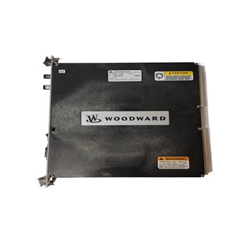
The Profibus Master Module (HE693PBM101/HE693PBM101-12) functions as a Profibus DP network master and is capable of controlling up to 64 slave devices. The Profibus DP application allows for the connection of I/O devices and simple field devices to an automation system via a Profibus network. Emphasis is on fast transmission of small data volumes. The PBM101/ PBM101-12 operates as Profibus DP module only and does not support other types of Profibus (FMS, PA).
GE HE693PBM101 Profibus Master Module
The PBM101/PBM101-12 function similarly except that PBM101 operates at 24MHz while the PBM101-12 operates at 48MHz. Profibus uses a Master-Slave type of communication with the PBM101/ PBM101-12 functioning as the master device. The PBM101/ PBM101-12 communicates with slave devices such as input/output devices, drives, valves, and measuring transmitters via a Profibus network. The PBM101/ PBM101-12 (when used with HE-APG Profibus Slave Modules) also allows communication between modules located in different PLC racks via the Profibus network. (For information covering HE-APG Slave Modules, see the User Manuals for the PBS105 and the PBM106.) 1.2 Profibus Overview Profibus, a token-passing network, supports one master (Type I) controlling the network and writing to the slave devices. Multiple masters (Type II), however, can read information simultaneously off the Profibus network. Master devices (PBM101/ PBM101-12) are used to determine the data communication on the bus. Slave devices are peripherals such as input/output devices, valves, drives, and measuring transmitters, etc. Slaves devices also include HE-APG Profibus Slave Modules located in PLCs that the PBM101/ PBM101-12 reads or writes to over the Profibus network. Slaves do not have bus access rights and only acknowledge received messages or send messages to the master when requested to do so. Data from the slave devices can be read by any master. All connected Slaves have the same priority. Up to 32 devices (masters or slaves) can be connected in one segment without using repeaters or up to 64 devices can be connected using repeaters.
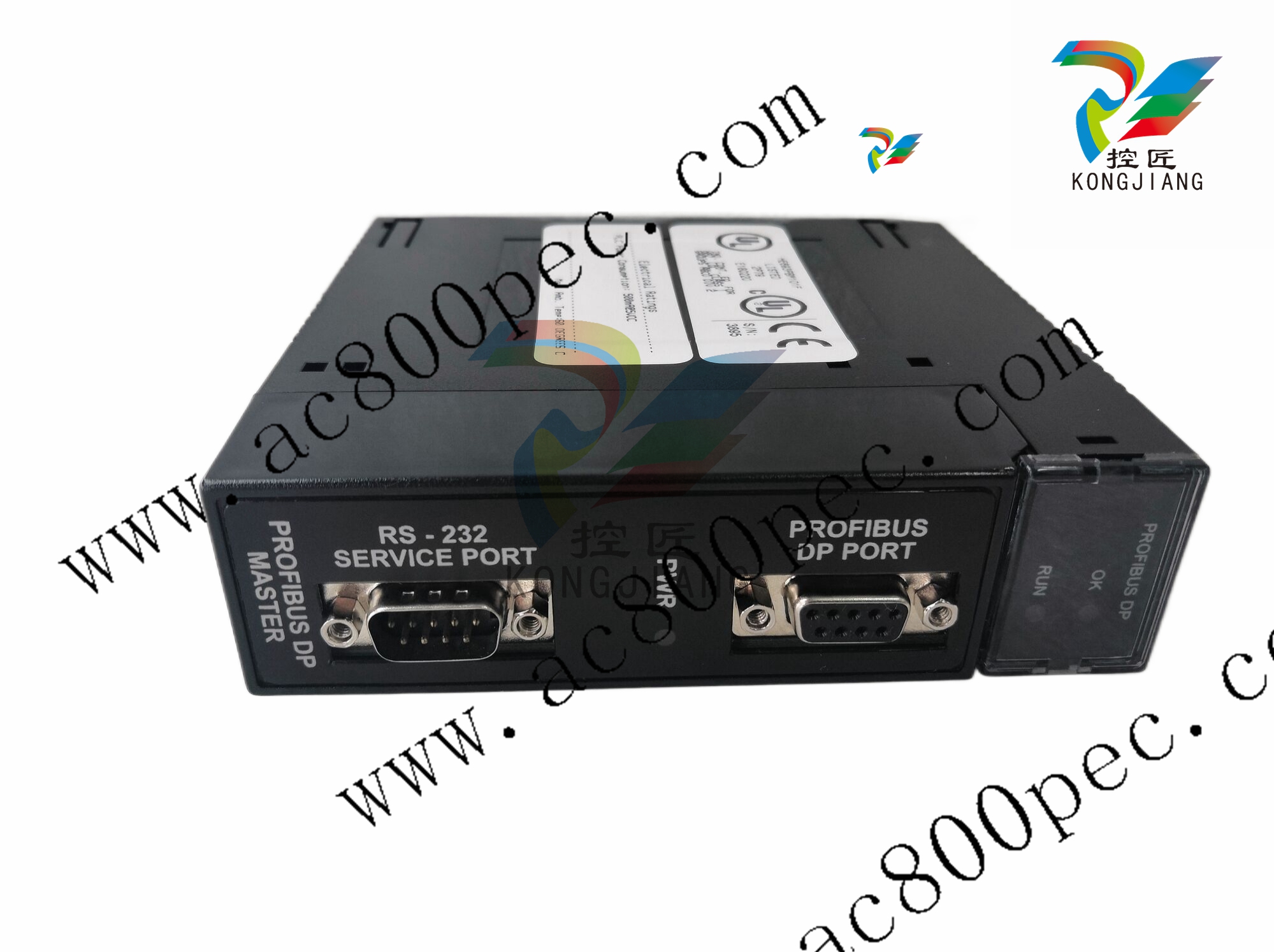
System Requirements and Limitations a. The PBM101/PBM101-12 require a CPU350 (or higher) with Firmware Version 8.0 (or higher). PBM101/PBM101-12: Up to 32 devices (masters or slaves) can be connected in one segment without using repeaters or up to 64 devices can be connected using repeaters. b. PBM101/PBM101-12: The number of slave devices on the network depends on the amount of total slave data produced and consumed on the network. Up to 504 bytes of total data can be produced on the network and up to 504 bytes of total data can be consumed from the network. Consumed data is reduced 2 bytes for every 1 word of diagnosis data. c. PBM101/PBM101-12: VersaPro Software (1.10) or Cimplicity Control (Version 2.20 or later) are required to configure the modules. The Series 9030 PLC is limited to 25 bytes of Extra Parameter Data. d. Logicmaster software and earlier versions of CPU Firmware do NOT support these modules. 1.4 Physical Layout of PBM101/PBM101-12 PROFIBUS DP MASTER PWR PROFIBUS DP OK RUN Figure 1.2 – Side View Figure 1.1 - Front Cover RS-232 SERVICE PORT PROFIBUS DP PORTMAN0219-05 15 APR 2003 PAGE 11 CH. 2 CHAPTER 2: INSTALLATION 2.1 PBM101/ PBM101-12 Mounting Requirements The PBM101/ PBM101-12 Module is designed to plug into any Series 90-30 local slot. The PBM101/ PBM101-12 requires at least a CPU350 model or higher with Firmware Revision 8. The PBM101/ PBM101-12 can not operate correctly with a lower version Firmware. Please refer to the appropriate manufacturer’s installation manual. 2.2 Profibus DP Connector The 9-pin Profibus DP connector is for physical connection between the slaves and the master. For further information on the cable and connectors, see Chapter 4 in this manual. 2.3 RS-232 Connector The RS-232 Service Port is used to upgrade the firmware specific to the slave. This port uses a standard RS-232 9-pin connector. 5 4 3 1 9 6 RI DTR RTS RXD CTS TXD DSR DCD Figure 2.1- Pin-out for the RS-232 2.4 LED Operation of PBM101/PBM101-12 There are three visible LED’s on the PBM101/ PBM101-12. the OK LED, RUN LED, and the POWER LED. Various combinations of these LED’s will indicate different states of the master. See Table 2.1 for the states indicated by the LED’s. Table 2.2 indicates fault conditions.
PBM101/ PBM101-12 Status Error/Diagnosis Reporting 2.5.1 PLC Status Bit Definition The PBM101/ PBM101-12 has 128 bits of diagnosis and status information reported to the PLC CPU. 64 bits are assigned as status bits, and 64 are assigned as diagnosis bits. The 64 status bits are by default assigned to the top of the existing memory map in the Settings tab of the PBM101/ PBM101-12 parameters screen (see Figure 3.4). The following explanation describes the Slave Status and indicates the information needed to setup the Slave Status parameters in the program language being used (such as Ladder Logic or C-Programming). The Slave Diagnosis inputs contain additional information about the slaves, which is useful for slave specific issues
| User name | Member Level | Quantity | Specification | Purchase Date |
|---|


-
 ABB UAD206A101 Programmable Logic Controller
 -
 ABB ACS800-04/U4 driver module
 -
 ABB UAD149A0011 3BHE014135R0011 Controller Module
 -
 ABB BSM series AC servo motor
 -
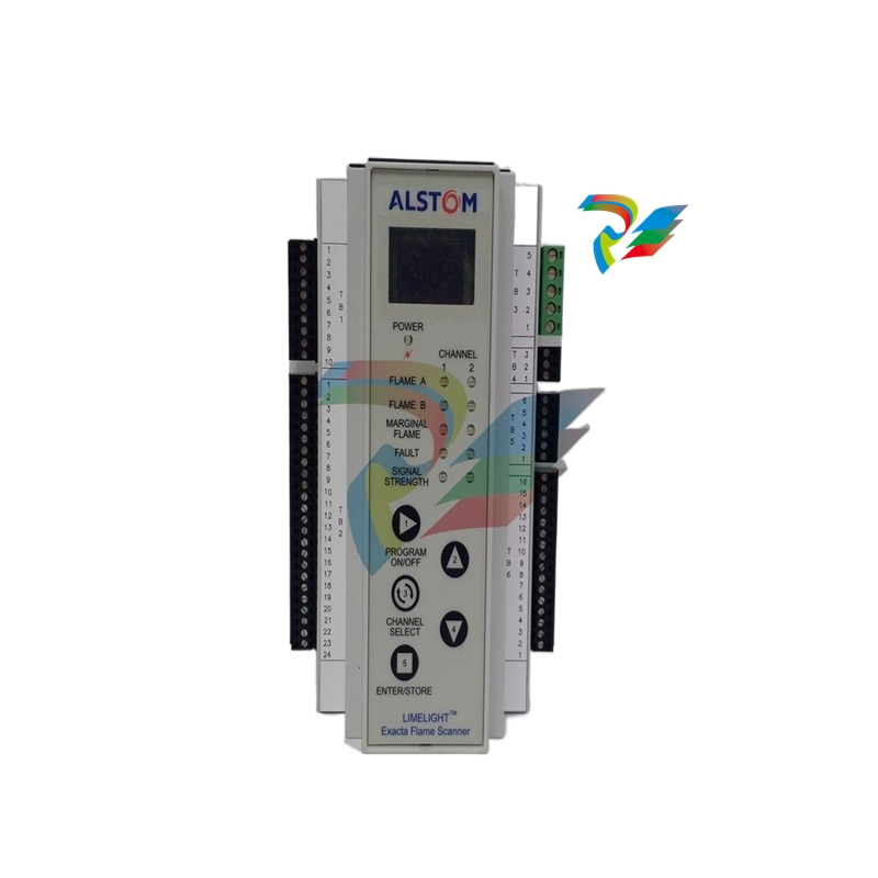
 ALSTOM DFI-150-0003- Limelight Diagnostic Board
 -
 ABB GCC960C102 motor driver
 -
 ABB INDUSTRIALDRIVES UCU-22, UCU-23 andUCU-24control units
 -
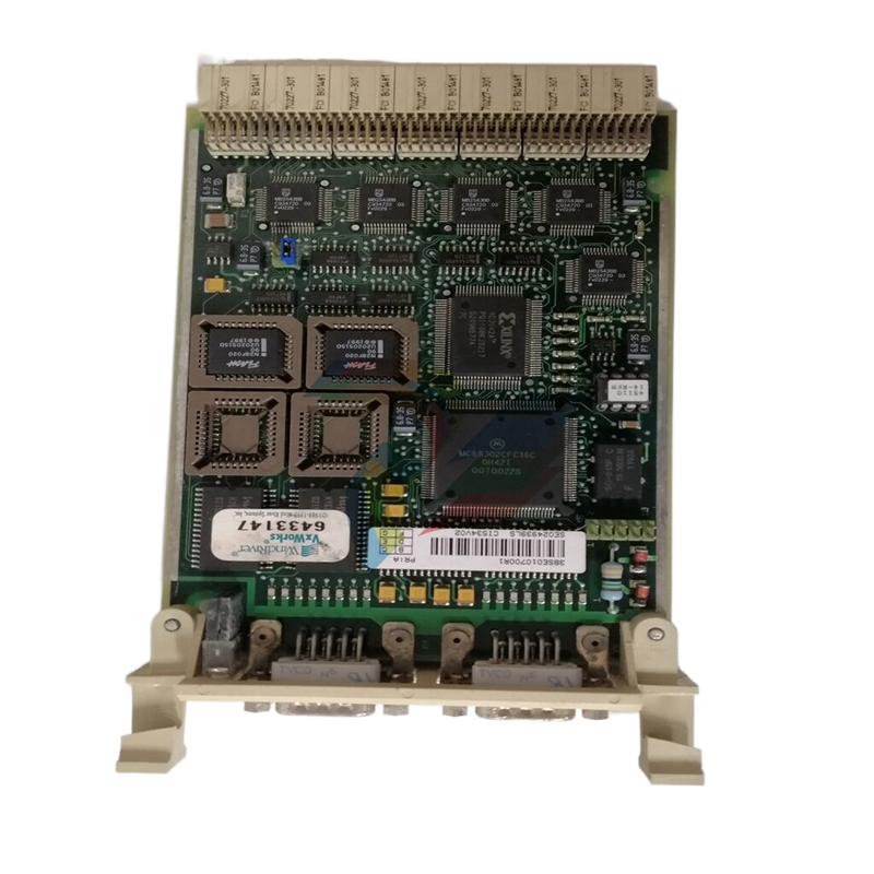 ABB XDD501A101 Bus Terminal Module
 -
 ABB S800 I/O DTM 5.3 module
 -
 ALSTOM N897164611M High Performance Control Module
 -
 ALSTOM N897164610L Pulse Output Module
 -
 ALSTOM N70032702L High Performance Control Module
 -
 ALSTOM MVAJ1L1GB0771B Auxiliary Transmission Relay
 -
 GE 239 MOTOR PROTECTION RELAY
 -
 ALSTOM ADVANCED MICRO CONTROLLER 2
 -
 Honeywell HC900 Process and Safety Controller
 -
 ABB ControlMaster CM10 Universal Process Controller
 -
 ABB dual power conversion switch
 -
 ABB RET 541/543/545 Transformer Terminal Device
 -
 ABB Relion ® RET620 Transformer Protection and Control Device
 -
 ABB Relion ® REU615 Voltage Protection and Control Device
 -
 ABB Relion ® REU615 Voltage Protection and Control Device
 -
 ABB REX615 Protection and Control Relay Products
 -
ABB PGC2000 series E2 process gas chromatograph
-
 ABB PROCOLOR P 88QT03 bus coupling module
 -
 Honeywell WEB-8000 Controller
 -
 ABB Protection Relay REX 521
 -
 ABB 5SGY3545L0020 Controller Module
 -
 ABB 5SGY3545L0017 module tension controller
 -
ABB 5SGY3545L003 IGCT control module
-
ABB SNAT609TAI 5761789-6H Industrial I/O Interface Card
-
ABB SNAT602TAC circuit board
-
 ABB SNAT603 CNT Control Board
 -
ABB SNAT634PAC pulse amplifier module
-
 ABB RK682011-BA RL0B 100 standard unit module
 -
 ABB PP846A 3BSE042238R2 Industrial Control Panel
 -
 ABB ZMU-02 inverter memory card
 -
 ABB 3BHE014135R0011 UAD149A0011 DCS POSITIONING CONTROL MODULE
 -
 ABB 3BHE014135R0011 UAD149 A00-0-11 I/O module
 -
 ABB MEASUREMENT & ANALYTICS Web Tension Systems with Tension Electronics PFEA113
 -
 ABB GDD471A001 2UBA0022R0001 motor control module
 -
ABB UCD224A103 high-performance control module
-
 ABB PDD205A0121 control module
 -
 ABB PDD205A1121 3BHE02535R1211 processor module
 -
 ABB DSDX453 Digital Input/Output Module
 -
ABB DSPC454 controller module
-
 Woodward ESDR4 Current Differential Protection Relay
 -
 Siemens SIJECT CI16iP StepB 6AТ1131-6DF21-0AB0 Compact Control
 -
 EtherNet/IP™ to Remote I/O or DH+ Gateway AN-X2-AB-DHRIO
 -
ABB 81EU01-E/R3210 Analog Signal Input Module
-
 ABB TK457V050 Industrial Temperature Controller
 -
 ABB DSRF197K01 Control Module
 -
 ABB TK802F SD802F/SD812F power cord
 -
ABB 3BHE03930R0101 I/O module
-
ABB 3BHB0040277R0101 GVC700AE01 thyristor module
-
 ABB 3BHB003154R0101 5SXE05-0156 IGCT module
 -
 RELIANCE INSPECTOR VCIB-06 Advanced Industrial Visual Display
 -
ABB AO2000-LS25 Laser analyzer
-
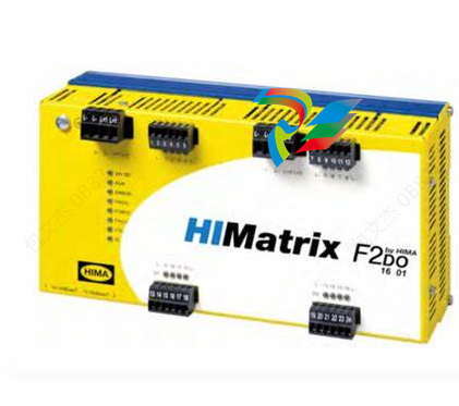 HIMA F8650X Central module
 -
ABB PM864AK01 Classic System 800xA hardware selector
-
 ABB 3BSE048845R1 CI868K01 IEC 61850 Interface
 -
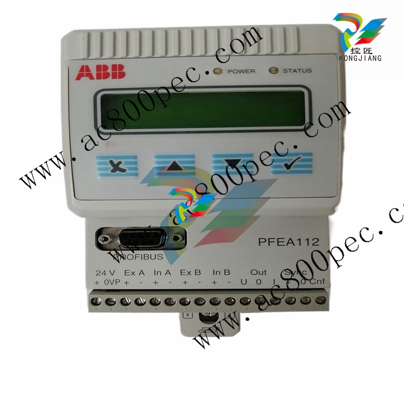 ABB 5SHY35L4520 Asymmetric Integrated Gate Converter Thyristor
 -
 ABB UNS0119A-P V101 3BHE029153R0101 processor module
 -
 Xycom 99212A-001 PC board
 -
 Xycom 144365-001 motherboard
 -
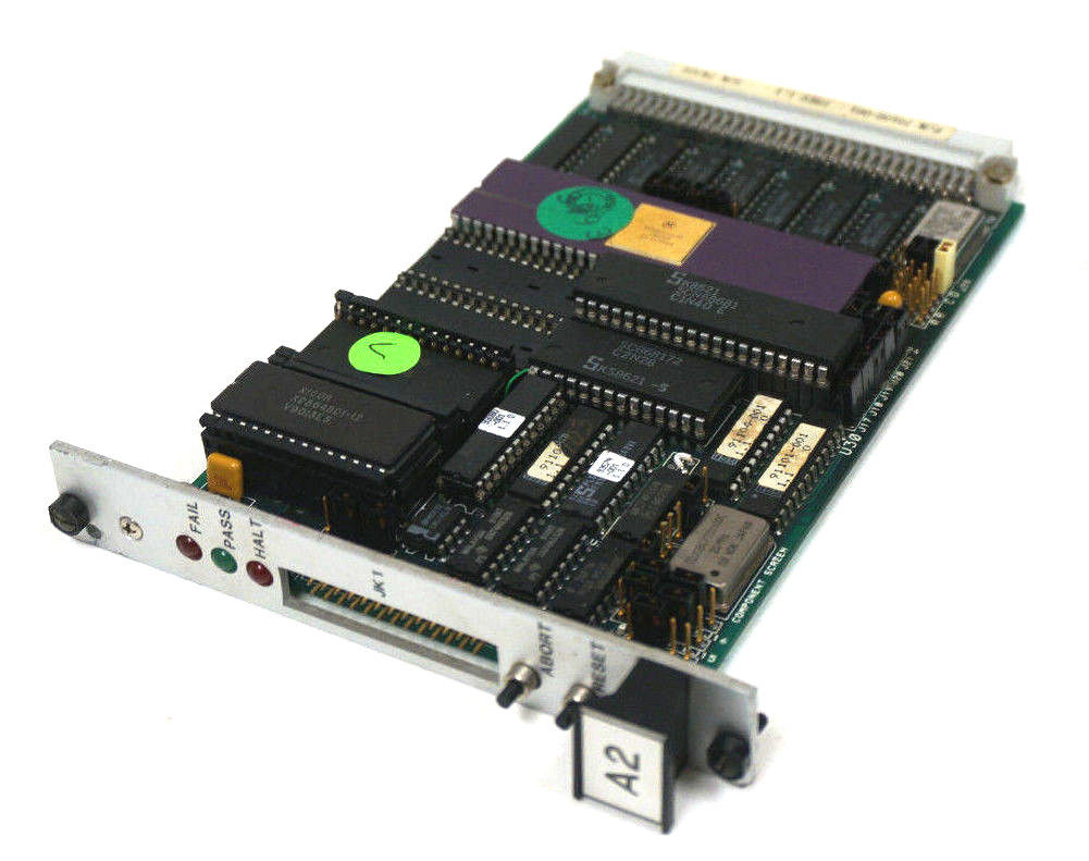
 XYCOM 70400-001 T3065-4 XVME-400 Board
 -
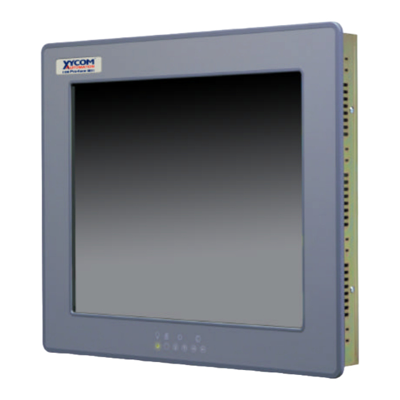
 Xycom Automation # 9450-2480016010000 Interface Monitor Model
 -
 XYCOM 70560-001 AIN XVME-560, VMEbus module card, PCB board
 -
 Xycom XVME-491 VMEbus 71491A PN70491-001
 -
 Xycom 99157-001 Circuit Board
 -
 Xycom 1341 egemin PM-070016 computer P/N 701301-01 TF-AEC-6910-C13
 -
 Xycom 8430 Industrial Controller Options 71338 115/230V P/N 8430-078122A002110
 -
 Xycom XVME-203 VME Digital Counter I/O Module Board PLC 70203-001
 -
 ABB UNS0119A-P V101 Controller Module
 -
 ABB GCC960C103 3BHE033067R0103 Controller Module
 -
 ABB GVC736CE101 High Performance AC Inverter
 -
 ABB PCD244A101 Terminal Card Module
 -
ABB 3BHE020356R0101 GFD212A motor thermal relay
-
ABB PDD500A101 power distribution module
-
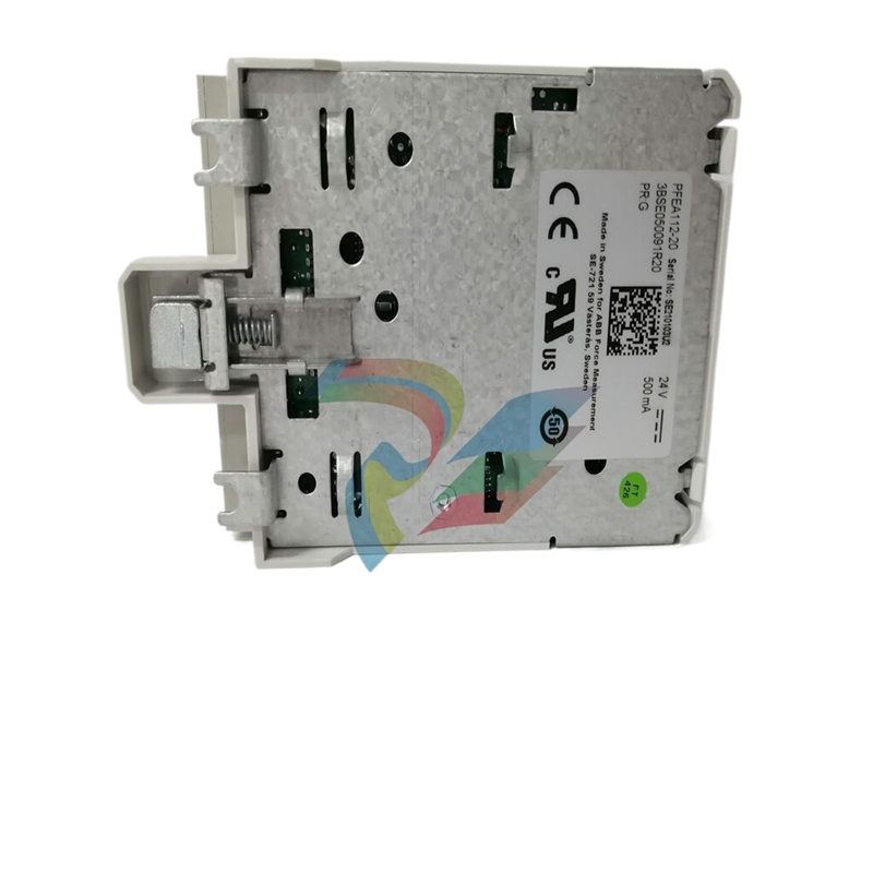 ABB PDD200A101 Industrial Control Module
 -
 Xycom 86863BA Control Card 86864-003/B
 -
 Xycom XVME-240 Digitale I/O-Karte für industriellen Einsatz
 -
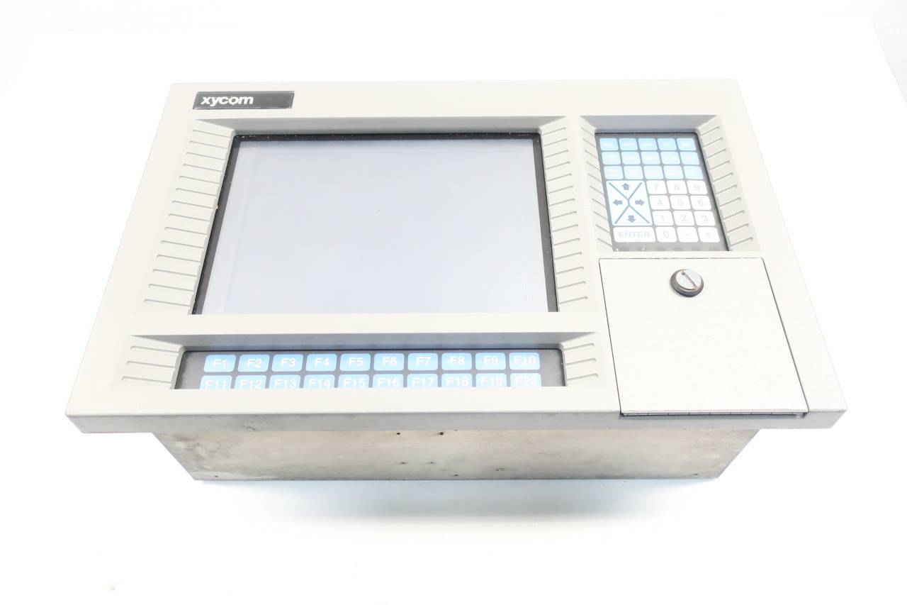
 Xycom 9450 PC/AT computer operator interface HMI screen display keyboard control
 -
 XYCOM XCME-540 Analog I/O Module VMEBUS 70540-001
 -
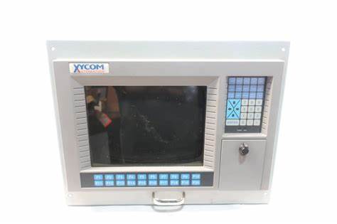
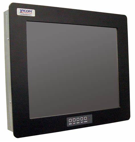
 XYCOM 9460 Touch Screen
 -
 Xycom Analog CDA XVME VME TI DSP SCSI I/O module sequence RS232 card board
 -
 ALSTOM MCGG62N1CB0753F Auxiliary Transmission Relay
 -
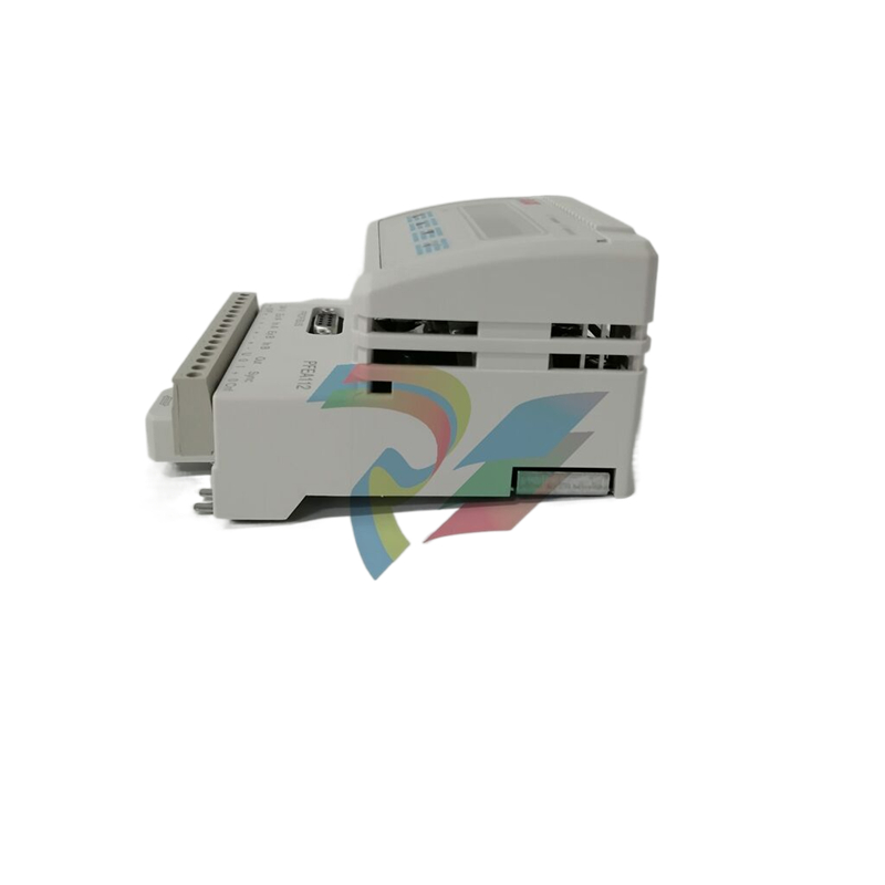 ABB S3N 3P 150A Standard thermal-magnetic
 -
 ABB SPIET800 Ethernet CIU Transfer Module
 -
 ABB SPAD 346 C3 Differential Protection
 -
 ABB 15.04.2005 Instrument Transformer
 -
 ABB FPX86-9329-C High Performance Industrial Controller
 -
 ABB ARCOL 0346 Industrial Control Module
 -
ABB ARCOL 0338 Controller Module
-
ABB ARCOL 0339 Industrial Inverter
-
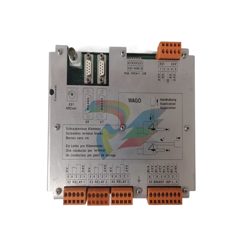 ABB 969-54 New Automation Controller Module DCS PLC Module
 -
 ABB 5SDD1060F0001 diode disk module
 -
ABB 5SDF0860H0003 Gate Cut off Thyristor Module
-
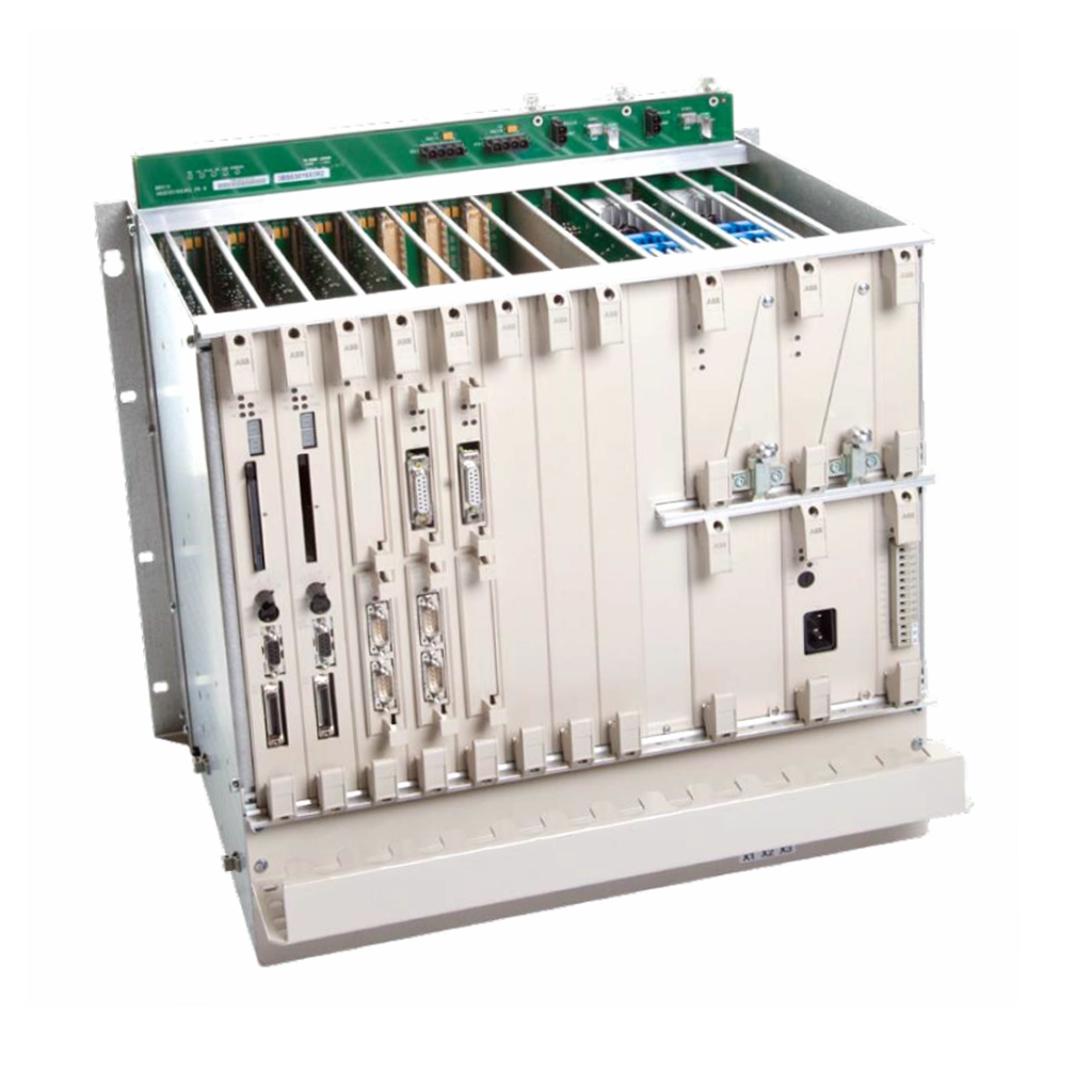 ABB KUC720AE01 Industrial High Frequency Control Module
 -
 ABB KUC720AE - High Performance Industrial Control Module
 -
ABB UFC718AE01 high-performance main circuit interface
-
 ABB 5SHX2645L0004 Integrated Gate Converter Thyristor
 -
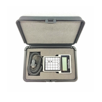
 Xycom 2000-KB1 94687-001 keyboard
 -
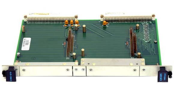
 Xycom 141452-001 5-slot amplifier card 141452001
 -
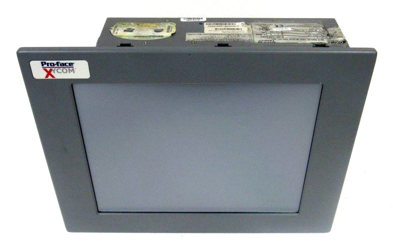
 Xycom 5015T/R2, Pro-face LCD 15" Monitor
 -
 Xycom 95212B-001 Module Circuit Board Card 95213-007 8503 PCB PWA Programmable Logic Controller
 -
 Xycom XVME-957 71957C-001 Circuit Board
 -
 XYCOM 99157-001 Circuit Board
 -
 Xycom 4115 T Operator Interface Panel 100-240v-ac
 -
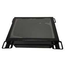 Xycom 2005 CRT Direct REPLACMENT LCD with Cable Kit
 -
 Xycom 4850 LCD monitor upgrade with cable kit 12 inches
 -
 Xycom 4810A 9-inch CRT LCD monitor upgrade
 -
ABB KOFA12D3 Indoor current transformers
-
.jpg) WOODWARD ProAct Positioner (Flex I/O)
WOODWARD ProAct Positioner (Flex I/O) -
.jpg) WOODWARD ProAct Positioner (16 pin), 3rd Generation
WOODWARD ProAct Positioner (16 pin), 3rd Generation -
 WOODWARD ProAct 75 Speed Control ( 1st Generation)
 -
.jpg) WOODWARD R-Series Actuators
WOODWARD R-Series Actuators -
.jpg) WOODWARD F-Series Positioners
WOODWARD F-Series Positioners -
 WOODWARD DVP Digital Valve Positioner
 -
.jpg) WOODWARD GSOV25HT Gas Fuel Shutoff Valve, 2.0”Flange
WOODWARD GSOV25HT Gas Fuel Shutoff Valve, 2.0”Flange -
.jpg) WOODWARD GSOV80 Gas Fuel Shutoff Valve, 2.0” Flange
WOODWARD GSOV80 Gas Fuel Shutoff Valve, 2.0” Flange -
 WOODWARD USOV Universal Shutoff Valves
 -
.jpg) WOODWARD LSOV25 Liquid Fuel Shutoff Valve
WOODWARD LSOV25 Liquid Fuel Shutoff Valve -
 WOODWARD LQ25 Standard Valves
 -
WOODWARD LQ6 Liquid Fuel Valve Actuator with On-board Driver
-
.jpg) WOODWARD GS50 Gas Fuel Valve Actuator with On-board Driver
WOODWARD GS50 Gas Fuel Valve Actuator with On-board Driver -
.jpg) WOODWARD GS40 Gas Fuel Valve Actuator with On-board Driver
WOODWARD GS40 Gas Fuel Valve Actuator with On-board Driver -
 WOODWARD Turbine Shutdown Trip Block Assemblies

