

K-WANG


- Telephone:+86-15305925923
- contacts:Mr.Wang
- Email:wang@kongjiangauto.com
ntroduction This document contains information that is not available in any other publication; therefore, we recommend you save it for future reference. This document discusses the features of the newly released firmware version 9.00 for CPU modules IC693CPU350 and IC693CPU360
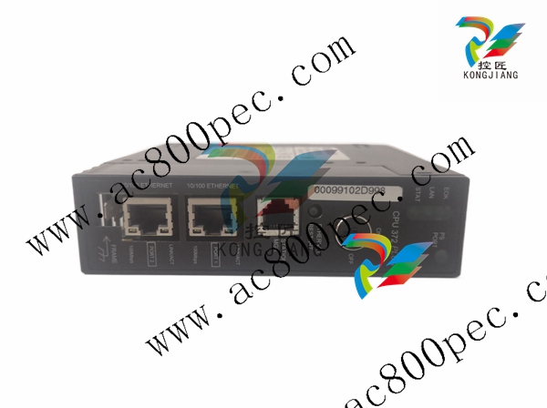
GE-IC693 CPU Modules IC693CPU350 IC693CPU360
New Features and Functionality of Firmware Release 9.00 • Software Floating-Point. The CPU350 and CPU360 support all of the floating-point function blocks that are currently supported by the CPU352. They are implemented in firmware using floating point emulation. These Floating-Point math function blocks are described in the IC693 PLC Reference Manual • CPU360 user memory increased to 240K bytes. %R, %AI, and %AQ references are configurable up to 16K of %R, 8K of %AI and 8K of %AQ memory using the MS-DOS PLC programming software, version 9.02. These three references will be configurable up to 32K in the next release (version 2.2) of the Windows PLC programming software. Configuration instructions for this feature are described in the MS-DOS IC693 Programming Software User’s Manual, and will be included in on-line help in the future release of the Windows PLC Programming Software, version 2.2. Note that the CPU350 does not support configurable user memory. Its user memory is set at a fixed value of 32K bytes • Sequential Event Recorder. A new function block, the Sequential Event Recorder, is available in firmware release 9.00. This function block can be used to record up to 1024 samples of 32 individual discrete (bit) references. Both of these CPUs support this function block. Instructions on programming the Sequential Event Recorder are found in the IC693 PLC Reference Manual. Hardware Identification The following table shows the revision level of the circuit boards used in the current version of these CPUs. CPU Catalog Number Circuit Board ID Circuit Board Version IC693CPU350-** CX*A* 44A739579-G01R04 or later IC693CPU360-** CX*A* 44A739579-G01R04 or later
Firmware Upgrade Kits If you wish to upgrade an existing CPU350 or CPU360 to firmware version 9.00. you may purchase the applicable kit identified in the following table. All previous versions are capable of being upgraded. Firmware 9.00 Upgrade Kit Catalog Number CPU Catalog Number Firmware Upgrade Kit Catalog Number IC693CPU350-(all versions) 44A747145-G01 IC693CPU360-(all versions) 44A747148-G01 Firmware Identification CPU Catalog Number Motherboard Firmware Version Daughterboard Firmware Version IC693CPU350-** Main: R*.** (**A*) Boot: R*.** (**A*) N/A IC693CPU360-** Main: R*.** (**A*) Boot: R*.** (**A*) N/A Functional Compatibility * • The Windows PLC Programming Software version 2.00 or later must be used to take advantage of C programming or Sequential Function Chart (SFC) subroutines. • Version 4.00 of the C toolkit must be used for C programming. • The MS-DOS PLC Programming Software Version 9.02 or later must be used to take advantage of the new features introduced in firmware release 9.00. These new features are listed in the section “New Features and Functionality of Firmware Release 9.00Operating Notes Special Operational Notes User Flash Contents User information, consisting of program, configuration, CPU ID (used for SNP communications), and status tables in RAM memory, will automatically be cleared if the CPU firmware in flash memory is changed. So you will need to restore these if upgrading firmware. A recommended procedure is to first back up your user information from RAM memory to Flash memory. Then write your new firmware to Flash memory (firmware is stored in a different location in Flash memory than that used for storing user information such as program, configuration, etc.). Finally, write your user information back out of Flash into RAM memory. As an alternative, your user information (program, configuration, etc.) can be restored from a computer-based backup program folder using your PLC programming software. The SNP ID must be set separately, using the programming software or the Hand-Held Programmer (HHP). Firmware Upgrade Hardware Requirements Note: The Model 35x and 36x CPU operating firmware is stored in FLASH memory. The firmware upgrade is provided on a floppy disk and must be serially downloaded from a Personal Computer. An IBM AT personal computer or better PC with a minimum 640K of RAM, one 3.5” floppy drive, MS-DOS version 3.3 or later (or Windows 95 or later), a hard drive, and one RS-232 serial port is required. In addition, a serial cable is required. The following serial cable kit is available from GE Fanuc
IC690ACC901 Mini Converter Kit with cable (RS-232/RS-485) Optionally, the cable can be assembled from the following parts: IC690ACC900 RS-232 to RS-485/422 Converter Unit IC693CBL303 15 Pin RS-485 Serial Cable IC690CBL705 25 Pin RS-232 Serial Cable * IC690CBL702 9 Pin RS-232 Serial Cable * * Only one of these cables is required. Selection depends on PC Serial Port Connector. Option Module Revision Requirements • Ethernet Interface Module Compatibility. All IC693 Ethernet Interface (IC693CMM321) modules used with these CPUs should be updated to IC693CMM321 firmware release 1.10 or later. This is also a requirement of the TCP/IP Ethernet version of the MS-DOS programming software. During a Run Mode Store (Alt + S hot key combination) of a large program block (greater than 14 kilobytes), the Ethernet module may time out, causing communications to fail. Changing the Communications Window to Run-to-Completion mode, or storing the program in Stop mode, will allow the store to take place successfully. • FBC Compatibility. FBC version 3 or later is required for these CPUs. Writing to Flash Using the Windows PLC Programming Software When writing very large programs to flash memory, it may be necessary to increase the Windows PLC programming software request timeout value to avoid receiving a request timeout message. An upper bound of 25 seconds is typically satisfactory Problems Resolved in Firmware Version 9.00-11.40 Keyswitch Configured as RUN/STOP Switch Previously, when the keyswitch was configured as a RUN/STOP switch, moving the keyswitch to the STOP position would not affect the current PLC state if the PLC was already in either STOP NO/IO or STOP IO SCAN mode. In firmware version 9.00. the keyswitch will now change the PLC to STOP IO SCAN or STOP NO/IO based on the configured value, even if the PLC is already in a “STOP” mode. Storing IC693CMM321 Configuration with Windows PLC Programming Software Issue It was possible to get a watchdog time-out failure when storing an IC693CMM321 configuration with the Windows PLC Programming software, Version 2.1 or earlier. This problem has been corrected in firmware version 9.00. RET_PBLOCK_LIST The RET_PBLOCK_LIST service request would only function correctly with 24 or less subroutines in the program in firmware version 8.00. The request now functions correctly with any number of subroutines in version 9.00. Service Request #7 SVC REQ #7 would allow ladder logic to set certain illegal dates such as 2/29/01. Illegal dates are no longer allowed to be entered by the user program. Documentation Instructions for using these two modules can be found in the latest version of the following manuals: General Configuration Instructions: IC693 PLC Programming Software User’s Manual Ladder Logic Programming: IC693 PLC Reference Manual Installation Instructions: IC693 PLC Installation Manual (firmware 9.0 features will be added to revision P of this manual)

| User name | Member Level | Quantity | Specification | Purchase Date |
|---|


- LTI Drives
- other
- ADLINK
- Beckhoff
- Shinkawa
- Other Brands
- AMAT
- Iba
- PEPPERL+FUCHS
- Aerotech
- WATLOW
- MAN
- ADVANCED
- Abaco
- YOKOGAWA
- KOLLMORGEN
- MEGGITT
- kong-sberg
- METSO
- Motorola
- NI
- OEMAX
- RELIANCE
- scanlab
- schneider
- uniop
- Vibro-Meter
- Honeywell
- Rolls-Royce
- MOOG
- GE
- B&R
- Woodward
- Yaskawa
- xYCOM
- Siemens
- Emerson
- HIMA
- Bently
- ZYGO
- FOXBORO
- OMACO
- PROSOFT
- ENTERASYS
- TRICONEX
- Parker
- Lenze
- KEBA
- Alstom
- CTI
- ABB
- A-B

-
 SUMITOMO T2100Z steel turning
 -
 SUMITOMO PSZ Turn Modular Quick Change Tool System
 -
 SUMITOMO EGU positive front corner chip breaker groove
 -
 SUMITOMO GND series slotting and cutting tools
 -
 SUMITOMO AC8000P series (AC8115P/AC8020P/AC8025P/AC8035P) steel turning
 -
 SUMITOMO AC6000M series (AC6020M/AC6030M/AC6135M/AC6145M) stainless steel turning
 -
 SUMITOMO ELECTRIC AC5000S series (AC5005S/AC5015S/AC5025S) heat-resistant alloy turning
 -
 SUMITOMO ELECTRIC AC4000K series (AC4010K/AC4015K/AC4125K) cast iron turning
 -
 SUMITOMO ELECTRIC AC1135U small lathe for turning small parts
 -
 SUMITOMO ELECTRIC AC1030U Material Blade
 -
 CCS 6900G/6900P Non Explosion proof Pressure Switch Installation and Maintenance Manual
 -
 BENDER WR70 × 175S (P)~WR200 × 500S (P) rectangular measuring current transformer
 -
 BENDER RCMA475LY B-type residual current monitor
 -
 BENDER IRDH575 A‑ISOMETER ® Insulation monitoring device
 -
 BENDER IRDH265 / IRDH365(ISOMETER ®) Insulation monitoring device
 -
 BENDER RCMA475LY AC/DC sensitive residual current monitor
 -
 Beckwith Electric M-3425A Generator Integrated Protection Relay
 -
 Automated Logic MEx816u I/O Expansion Module
 -
 ASEM HT2150 Fanless Industrial Panel X86
 -
 Advantest U3771/U3772 portable microwave millimeter wave spectrum analyzer
 -
 Advantest R6144 Programmable DC Voltage/Current Source (Calibration Source)
 -
 Aerotech UNIDEX 100/U100i single axis motion controller
 -
 Aerotech Ndrive MP Ultra Compact PWM Digital Servo Driver
 -
 Aerotech Ndrive HPe 10/20/30 High Performance PWM Digital Servo Drive
 -
 Aerotech Ndrive Linear (HLe/ML) Linear Servo Drive
 -
 Aerotech Ndrive CP Compact PWM Digital Servo Driver
 -
 Aerotech Ndrive Linear (HLe/CL/ML) linear servo drive
 -
 Aerotech Ndrive HL (EDU176 Rev1.08b) Digital Servo Drive
 -
 Aerotech Ndrive HP10/20/30 PWM Digital Servo Drive
 -
 Aerotech Ndrive series digital servo drives
 -
 SIGMATEK TAE 1941 Touch Display Unit
 -
 SIGMATEK TAE 151 Touch Display Unit
 -
 SIGMATEK AKM series servo motor
 -
 SIGMATEK S-DIAS Control System
 -
 SIGMATEK Human Machine Interface (HMI)
 -
 SIGMATEK DIAS Drive 310-23 servo amplifier
 -
 SIGMATEK CCP 521 C-DIAS processor module
 -
 MEGMEET L6 series electric drive
 -
 Sysmex XN-1000/XN-2000 Hematology Analyzer
 -
 Sysmex XN-L series (XN-530/XN-430/XN-330) fully automatic blood cell analyzer
 -
 Sysmex XN-9000 Series Fully Automated Blood Analysis Pipeline
 -
 LTI‑Motion ServoOne Field Bus Systems PROFIBUS and PROFINET
 -
 Micro Innovation MICRO PANEL GF1 Color Touch Human Computer Interface
 -
 Micro Innovation WINbloc Distributed Remote I/O System
 -
 Micro Innovation MICRO PANEL GS-2 Industrial Touch Visualization Operation Panel (HMI)
 -
 LTi LST/LSH series synchronous servo motor
 -
 LTi CDE/CDB3000 positioning controller
 -
 ENOTEC SILOTEC ® Installation and Operation Instructions for 8000 Silo Monitoring O ₂/CO ₑ Analyzer System
 -
 ENOTEC ENSITU ® 7000 Compact Oxygen Transmitter Probe
 -
 ENOTEC COMTEC ® Installation and Operation Instructions for 6000 ATEX GasEx Explosion proof O ₂/COE Analyzer System
 -
 ENOTEC Integrated Products
 -
 ENOTEC OXITEC ® 500E Extraction Oxygen Analyzer
 -
 KUKA KR CS Box-2 Compact Controller for Four Axis SCARA Robot
 -
 KUKA KR C5 slim-2 Robot Controller
 -
 KUKA KR C5 micro With KUKA System Software (KSS/VSS) Assembly Instructions
 -
 KUKA KR C5 micro controller
 -
 KUKA KR C5 Controller Assembly Instructions
 -
 KUKA KR C5 compactcab and KR C5 small-size cab cabinets
 -
 KUKA KR C4 smallsize-2 small robot control cabinet
 -
 KUKA KR C4 Midsize/KR C4 Midsize CK Assembly Manual
 -
 ENOTEC ® Installation and Operation Instructions for 5000/5000+Oxygen Analyzer System
 -
 KUKA KR C4 extended; KR C4 extended CK Assembly Instructions Assembly Manual
 -
 Assembly/Installation Manual for KUKA KR C4 Compact Control Cabinet
 -
 KUKA Sunrise Cabinet Med Medical Collaborative Robot Special Control Cabinet
 -
 KUKA Sunrise Cabinet Next Generation Small Control Cabinet
 -
 KUKA KR C4 Smallsize-2 family's smallest control cabinet
 -
 KUKA KR C4 midsize; KR C4 midsize CK medium-sized control cabinet
 -
 KUKA KR C4 extended is a high-power multi axis control cabinet
 -
 General installation and operation instructions for KUKA KR C4 and KR C4 CK controllers
 -
 KUKA KR C4 compact controller operation instructions
 -
 Installation and Operation Instructions for KUKA Robot Arm
 -
 KUKA TITAN-2 Ultra Ground Overloading Six Axis Robot
 -
 Assembly instructions for KUKA KR SCARA-2 CS series robotic arm body
 -
 KUKA MA KR SCARA X Installation Guide
 -
 KUKA KR FORTEC-2 Ultra Heavy duty Ground Six Axis Robot Mechanical Assembly Manual
 -
 KUKA KR FORTEC-2 new generation heavy-duty ground six axis robot
 -
 KUKA Robots KR 1000 titan; KR 1000 L750 titan With F Variants Assembly Instructions
 -
 KUKA KR 600 FORTEC heavy-duty six axis ground mounted industrial robot
 -
 KUKA KR 500 MT FORTEC Heavy duty Six Axis Industrial Robot
 -
 KUKA KR 360 FORTEC Heavy duty Six Axis Industrial Robot
 -
 KUKA Sunrise Cabinet Med Medical Edition Robot Controller User Manual
 -
 KUKA Robots KR SCARA HO Assembly Instructions
 -
 KUKA Robots KR QUANTEC-2 PA Assembly Instructions
 -
 KUKA Robots KR QUANTEC-2 K and KR QUANTEC-2 P With K-F and P-C Variants Assembly Instructions
 -
 KUKA Robots KR QUANTEC-2 HO Assembly Instructions
 -
 KUKA Robots KR QUANTEC-2 HC Assembly Instructions
 -
 KUKA KR QUANTEC-2 series heavy-duty ground mounted six axis industrial robot
 -
 KUKA KR QUANTEC PA series heavy-duty palletizing robot
 -
 KUKA KR IONTEC-2 series six axis industrial robot
 -
 KUKA KR IONTEC ultra series six axis heavy-duty industrial robot
 -
 KUKA KR IONTEC HO Robot Assembly Manual
 -
 KUKA Robots KR CYBERTECH-3 HW Assembly Instructions
 -
 KUKA Robots KR CYBERTECH-3 Assembly Instructions
 -
 KUKA Robots KR CYBERTECH-2 arc Assembly Instructions
 -
 KUKA Robots KR CYBERTECH nano-2 Assembly Instructions
 -
 KUKA KR CYBERTECH CR HO (KR 20 R1810-HO) assembly instructions
 -
 KUKA Robots KR CYBERTECH With F variant Assembly Instructions
 -
 KUKA KR CYBERTECH CR (KR 20 R1810-CR) Clean Room (CR) Version 6-Axis Industrial Robot
 -
 KUKA KR AGILUS-3 ultra series small six axis serial robot
 -
 KUKA KR 300 R2700-2 C-F Cast Ceiling Mounted 6-Axis Heavy duty Industrial Robot
 -
 KUKA KR 20 R1820-2 E Six Axis Industrial Robot
 -
 Assembly instructions for KUKA KR AGILUS-3 small six axis robot
 -
 KUKA KR AGILUS-2 New Generation Small Six Axis Robot
 -
 KUKA KR 1000 1300 titan PA; KR 1000 L950 titan PA With F Variants Assembly Instructions
 -
 KUKA KR 700 PA/KR 700 PA Arctic Installation Guide
 -
 KUKA KR 18 R1450-3 PP six axis ground mounted industrial robot
 -
 KUKA 12 SCARA Series 4-axis SCARA Horizontal Joint Robot
 -
 KUKA KR 4 R600 Small Six Axis Industrial Robot
 -
 Installation Guide for KUKA KR 3 R540 Small 6-Axis Industrial Robot
 -
 KUKA LBR iiwa CR Clean 7-Axis Lightweight Collaborative Robot
 -
 KUKA KR AGILUS sixx series six axis industrial robot operation instructions
 -
 KUKA 4-axis heavy-duty SCARA horizontal multi joint robot KR 60 R1200 Z400 CS
 -
 KUKA KR 23 SCARA-2 CS SCARA Horizontal Multi Joint Robot
 -
 KUKA KR 20 SCARA CS Robot Assembly Instructions
 -
 KUKA KR 15 DELTA-2 Assembly Manual
 -
 KUKA KR 13 SCARA-2 CS Assembly Manual
 -
 KUKA KR 3 D1200 (Standard Delta Robot) Assembly Instructions
 -
 KUKA KR 3 D1200 HM Assembly Manual
 -
 KUKA LBR Med 7 R800, LBR Med 14 R820 Medical Edition Robot
 -
 KUKA Robots LBR iiwa 7 R800, LBR iiwa 14 R820 Operating instructions
 -
 KUKA LBR iiwa CR (Clean Room Version Robot) Operating Instructions
 -
 Lauer PCStopline series text operation panel
 -
 KUKA LBR iisy (MA_LBR_iisy V5) assembly manual
 -
 KUKA LBR iisy 3 R760 Assembly Manual
 -
 KUKA LBR iico Collaborative Robot Assembly Manual
 -
 Lauer LCAstarline (LCA300/LCA320/LCA325) Text Display Screen
 -
 Lauer PCS950/PCS950c/PCS950e operation console
 -
 Lauer EPC Series Industrial Embedded Human Computer Integrated PC User Guide

K-JIANG

Add: Jimei North Road, Jimei District, Xiamen, Fujian, China
Tell:+86-15305925923