

K-WANG


- Telephone:+86-15305925923
- contacts:Mr.Wang
- Email:wang@kongjiangauto.com
The PACSystems* RX3i Redundancy CPU can be used to perform real time control of machines, processes, and material handling systems. The CPU communicates with the programmer and HMI devices via a serial port using SNP Slave protocol. It communicates with I/O and smart option modules over a dual backplane bus that provides:
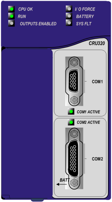
GE IC695CRU320 Redundancy CPU
High-speed PCI backplane for fast throughput of new
advanced I/O.
▪ Serial backplane for easy migration of existing
Series 90*-30 I/O.
Features
▪ Hot standby (HSB) redundancy. Two redundant units
make up a redundancy system. Each unit requires one
Redundancy CPU (IC695CRU320) and a redundancy
Memory Xchange module (IC695RMX128/228) configured
as a redundancy link.
▪ Contains 64 Mbytes of battery-backed user memory and
64 Mbytes of non-volatile flash user memory.
▪ Provides access to bulk memory via reference table %W.
▪ Configurable data and program memory.
▪ Programming in Ladder Diagram, Structured Text,
Function Block Diagram, and C. Refer to PACSystems RX7i
& RX3i CPU Programmer’s Reference Manual, GFK-2950.
▪ Supports auto-located Symbolic Variables that can use
any amount of user memory.
▪ Reference table sizes include 32Kbits for discrete %I and
%Q and up to 32K words each for analog %AI and %AQ.
▪ Supports most Series 90-30 modules and expansion
racks. For a list of supported I/O, Communications,
Motion, and Intelligent modules, refer to the PACSystems
RX3i System Manual, GFK-2314F or later.
▪ Supports up to 512 program blocks. Maximum size for a
block is 128KB.
▪ CPU firmware may be upgraded in the field.
▪ CPU supports firmware upgrades of modules in its
backplane.
▪ Two serial ports: an RS-485 serial port and an RS-232
serial port.
▪ Ethernet communications via the rack-based Ethernet
Interface module (IC695ETM001). For details on Ethernet
capabilities, refer to PACSystems RX7i & RX3i TCP/IP
Ethernet Communications User Manual, GFK-2224.
▪ Time Synchronization to SNTP Time Server on Ethernet
network when used with Ethernet Release 5.0 or later.
▪ Compliant with EU RoHS Directive 2002/95/EC using the
following exemp
Ordering Information
Catalog Number Description
IC695CRU320 RX3i 1GHz Celeron M CPU with 64MB User Memory
IC695ACC302 Smart Auxiliary Battery for Memory Retention
IC693ACC302 Auxiliary Battery for Memory Retention
IC690RBT001 Rechargeable Battery for Memory Retention
Warning – Use only GEIP approved auxillary battery packs listed above. Use of another battery may
present a risk of fire or explosion.
Hot Standby CPU Redundancy Features
For details on the configuration and operation of a Hot Standby CPU redundancy system, refer to the PACSystems
Hot Standby CPU Redundancy User’s Manual, GFK-2308.
▪ Supports single and redundant Ethernet remote I/O LANs through Ethernet Network Interface Unit (ENIU)
modules
▪ Supports simplex and redundantly controlled PROFINET remote IO (requires firmware version 8.00 or later)
▪ Survives any one single point of failure
▪ Bumpless switching
o Synchronized CPUs
o One scan switching
o Transfer data size up to 2Mbytes; selected in CPU hardware configuration and in variable properties
▪ Supports two redundancy communications links
▪ Online repair of failed component
▪ Online programming
▪ Redundancy Memory Xchange Module
o Manual toggle switch for role switching, which transitions control from the active unit to the backup unit
o Redundancy status LEDs
▪ Application-initiated role switching to switch the active unit to backup status
▪ Redundancy status bits and message logging
▪ Memory error checking and correction (ECC) single bit correcting and multiple bit checking
▪ Background diagnostics
HSB Control Strategy
The HSB control strategy has the following characteristics:
▪ Active unit does not automatically switch to primary on resynchronization
▪ Critical control data plus all redundant outputs must be included in the output data transfer
▪ Bumpless switchover from active unit to backup unit
Specifications: CRU320
CPU Performance For CRU320 performance data, refer to Appendix A of the PACSystems CPU Reference
Manual, GFK-2222V or later.
Battery: Memory retention For battery selection, installation and estimated life, refer to the PACSystems RX3i and RX7i
Battery and Energy Pack Manual, GFK-2741
Program storage Up to 64 MB of battery-backed RAM
64 MB of non-volatile flash user memory
Power requirements +3.3 Vdc: 1.0 Amps nominal
+5 Vdc: 1.2 Amps nominal
Operating Temperature 0 to 60°C (32°F to 140°F)
Floating point Yes
Time of Day Clock accuracy Maximum drift of 2 seconds per day
Elapsed Time Clock (internal
timing) accuracy
0.01% maximum
Embedded communications RS-232. RS-485
Serial Protocols supported Modbus RTU Slave, SNP, Serial I/O
Backplane Dual backplane bus support: RX3i PCI and high-speed serial bus
PCI compatibility System designed to be electrically compliant with PCI 2.2 standard
Program blocks Up to 512 program blocks. Maximum size for a block is 128KB.
Memory %I and %Q: 32Kbits for discrete
%AI and %AQ: configurable up to 32Kwords
%W: configurable up to the maximum available user RAM
Symbolic: configurable up to 64 Mbytes
Flash memory endurance
rating
100.000 write/erase cycles minimum
Memory error checking and
correction (ECC)
Single bit correcting and multiple bit checking.
Switchover Time1 Maximum 1 logic scan, minimum 3.133 msec.
Typical Base Sweep Time
(Reference Data Transfer List
Impact)2
3.66 msec: 1K Discrete I/O, 125 Analog I/O and 1K Registers
3.87 msec: 2K Discrete I/O, 250 Analog I/O and 2K Registers
4.30 msec: 4K Discrete I/O, 500 Analog I/O and 4K Registers
5.16 msec: 8K Discrete I/O, 1K Analog I/O and 8K Registers
Maximum amount of data in
transfer list
Up to 2 Mbytes
Number of redundancy links
supported
Up to two IC695RMX128/228 synchronization links are supported.
| User name | Member Level | Quantity | Specification | Purchase Date |
|---|


- LTI Drives
- other
- ADLINK
- Beckhoff
- Shinkawa
- Other Brands
- AMAT
- Iba
- PEPPERL+FUCHS
- Aerotech
- WATLOW
- MAN
- ADVANCED
- Abaco
- YOKOGAWA
- KOLLMORGEN
- MEGGITT
- kong-sberg
- METSO
- Motorola
- NI
- OEMAX
- RELIANCE
- scanlab
- schneider
- uniop
- Vibro-Meter
- Honeywell
- Rolls-Royce
- MOOG
- GE
- B&R
- Woodward
- Yaskawa
- xYCOM
- Siemens
- Emerson
- HIMA
- Bently
- ZYGO
- FOXBORO
- OMACO
- PROSOFT
- ENTERASYS
- TRICONEX
- Parker
- Lenze
- KEBA
- Alstom
- CTI
- ABB
- A-B

-
 HIMA X-DI 64 01 Digital Input Module
 -
 Hirschmann MICE MS20/MS30 Industrial Switch Installation Instructions
 -
 Exor UniOP ePAD05/ePAD06 Compact HMI Industrial Human Machine Panel
 -
 Exor Effectiveness View eV058- TST/eV058- TNT Industrial Touch Screen HMI Human Machine Panel
 -
 Esd VME-PMC CADDY/2 Intelligent VME-PMC Carrier Board
 -
 Installation Instructions for Elmo Gold Tuba (G-TUB) Servo Drive
 -
 Eaton COM-MPB1-TP/COM-MPB2-TP communication module
 -
 Delta Tau Turbo PMAC2 PCI Ultralite Programmable Multi Axis Motion Controller
 -
 DATA PATTERNS DP-VME-5114 module
 -
 CMZ SVM Series Independent Two Phase Synchronous Servo Driver SVM1608 Product Specification
 -
 SUMITOMO T2100Z steel turning
 -
 SUMITOMO PSZ Turn Modular Quick Change Tool System
 -
 SUMITOMO EGU positive front corner chip breaker groove
 -
 SUMITOMO GND series slotting and cutting tools
 -
 SUMITOMO AC8000P series (AC8115P/AC8020P/AC8025P/AC8035P) steel turning
 -
 SUMITOMO AC6000M series (AC6020M/AC6030M/AC6135M/AC6145M) stainless steel turning
 -
 SUMITOMO ELECTRIC AC5000S series (AC5005S/AC5015S/AC5025S) heat-resistant alloy turning
 -
 SUMITOMO ELECTRIC AC4000K series (AC4010K/AC4015K/AC4125K) cast iron turning
 -
 SUMITOMO ELECTRIC AC1135U small lathe for turning small parts
 -
 SUMITOMO ELECTRIC AC1030U Material Blade
 -
 CCS 6900G/6900P Non Explosion proof Pressure Switch Installation and Maintenance Manual
 -
 BENDER WR70 × 175S (P)~WR200 × 500S (P) rectangular measuring current transformer
 -
 BENDER RCMA475LY B-type residual current monitor
 -
 BENDER IRDH575 A‑ISOMETER ® Insulation monitoring device
 -
 BENDER IRDH265 / IRDH365(ISOMETER ®) Insulation monitoring device
 -
 BENDER RCMA475LY AC/DC sensitive residual current monitor
 -
 Beckwith Electric M-3425A Generator Integrated Protection Relay
 -
 Automated Logic MEx816u I/O Expansion Module
 -
 ASEM HT2150 Fanless Industrial Panel X86
 -
 Advantest U3771/U3772 portable microwave millimeter wave spectrum analyzer
 -
 Advantest R6144 Programmable DC Voltage/Current Source (Calibration Source)
 -
 Aerotech UNIDEX 100/U100i single axis motion controller
 -
 Aerotech Ndrive MP Ultra Compact PWM Digital Servo Driver
 -
 Aerotech Ndrive HPe 10/20/30 High Performance PWM Digital Servo Drive
 -
 Aerotech Ndrive Linear (HLe/ML) Linear Servo Drive
 -
 Aerotech Ndrive CP Compact PWM Digital Servo Driver
 -
 Aerotech Ndrive Linear (HLe/CL/ML) linear servo drive
 -
 Aerotech Ndrive HL (EDU176 Rev1.08b) Digital Servo Drive
 -
 Aerotech Ndrive HP10/20/30 PWM Digital Servo Drive
 -
 Aerotech Ndrive series digital servo drives
 -
 SIGMATEK TAE 1941 Touch Display Unit
 -
 SIGMATEK TAE 151 Touch Display Unit
 -
 SIGMATEK AKM series servo motor
 -
 SIGMATEK S-DIAS Control System
 -
 SIGMATEK Human Machine Interface (HMI)
 -
 SIGMATEK DIAS Drive 310-23 servo amplifier
 -
 SIGMATEK CCP 521 C-DIAS processor module
 -
 MEGMEET L6 series electric drive
 -
 Sysmex XN-1000/XN-2000 Hematology Analyzer
 -
 Sysmex XN-L series (XN-530/XN-430/XN-330) fully automatic blood cell analyzer
 -
 Sysmex XN-9000 Series Fully Automated Blood Analysis Pipeline
 -
 LTI‑Motion ServoOne Field Bus Systems PROFIBUS and PROFINET
 -
 Micro Innovation MICRO PANEL GF1 Color Touch Human Computer Interface
 -
 Micro Innovation WINbloc Distributed Remote I/O System
 -
 Micro Innovation MICRO PANEL GS-2 Industrial Touch Visualization Operation Panel (HMI)
 -
 LTi LST/LSH series synchronous servo motor
 -
 LTi CDE/CDB3000 positioning controller
 -
 ENOTEC SILOTEC ® Installation and Operation Instructions for 8000 Silo Monitoring O ₂/CO ₑ Analyzer System
 -
 ENOTEC ENSITU ® 7000 Compact Oxygen Transmitter Probe
 -
 ENOTEC COMTEC ® Installation and Operation Instructions for 6000 ATEX GasEx Explosion proof O ₂/COE Analyzer System
 -
 ENOTEC Integrated Products
 -
 ENOTEC OXITEC ® 500E Extraction Oxygen Analyzer
 -
 KUKA KR CS Box-2 Compact Controller for Four Axis SCARA Robot
 -
 KUKA KR C5 slim-2 Robot Controller
 -
 KUKA KR C5 micro With KUKA System Software (KSS/VSS) Assembly Instructions
 -
 KUKA KR C5 micro controller
 -
 KUKA KR C5 Controller Assembly Instructions
 -
 KUKA KR C5 compactcab and KR C5 small-size cab cabinets
 -
 KUKA KR C4 smallsize-2 small robot control cabinet
 -
 KUKA KR C4 Midsize/KR C4 Midsize CK Assembly Manual
 -
 ENOTEC ® Installation and Operation Instructions for 5000/5000+Oxygen Analyzer System
 -
 KUKA KR C4 extended; KR C4 extended CK Assembly Instructions Assembly Manual
 -
 Assembly/Installation Manual for KUKA KR C4 Compact Control Cabinet
 -
 KUKA Sunrise Cabinet Med Medical Collaborative Robot Special Control Cabinet
 -
 KUKA Sunrise Cabinet Next Generation Small Control Cabinet
 -
 KUKA KR C4 Smallsize-2 family's smallest control cabinet
 -
 KUKA KR C4 midsize; KR C4 midsize CK medium-sized control cabinet
 -
 KUKA KR C4 extended is a high-power multi axis control cabinet
 -
 General installation and operation instructions for KUKA KR C4 and KR C4 CK controllers
 -
 KUKA KR C4 compact controller operation instructions
 -
 Installation and Operation Instructions for KUKA Robot Arm
 -
 KUKA TITAN-2 Ultra Ground Overloading Six Axis Robot
 -
 Assembly instructions for KUKA KR SCARA-2 CS series robotic arm body
 -
 KUKA MA KR SCARA X Installation Guide
 -
 KUKA KR FORTEC-2 Ultra Heavy duty Ground Six Axis Robot Mechanical Assembly Manual
 -
 KUKA KR FORTEC-2 new generation heavy-duty ground six axis robot
 -
 KUKA Robots KR 1000 titan; KR 1000 L750 titan With F Variants Assembly Instructions
 -
 KUKA KR 600 FORTEC heavy-duty six axis ground mounted industrial robot
 -
 KUKA KR 500 MT FORTEC Heavy duty Six Axis Industrial Robot
 -
 KUKA KR 360 FORTEC Heavy duty Six Axis Industrial Robot
 -
 KUKA Sunrise Cabinet Med Medical Edition Robot Controller User Manual
 -
 KUKA Robots KR SCARA HO Assembly Instructions
 -
 KUKA Robots KR QUANTEC-2 PA Assembly Instructions
 -
 KUKA Robots KR QUANTEC-2 K and KR QUANTEC-2 P With K-F and P-C Variants Assembly Instructions
 -
 KUKA Robots KR QUANTEC-2 HO Assembly Instructions
 -
 KUKA Robots KR QUANTEC-2 HC Assembly Instructions
 -
 KUKA KR QUANTEC-2 series heavy-duty ground mounted six axis industrial robot
 -
 KUKA KR QUANTEC PA series heavy-duty palletizing robot
 -
 KUKA KR IONTEC-2 series six axis industrial robot
 -
 KUKA KR IONTEC ultra series six axis heavy-duty industrial robot
 -
 KUKA KR IONTEC HO Robot Assembly Manual
 -
 KUKA Robots KR CYBERTECH-3 HW Assembly Instructions
 -
 KUKA Robots KR CYBERTECH-3 Assembly Instructions
 -
 KUKA Robots KR CYBERTECH-2 arc Assembly Instructions
 -
 KUKA Robots KR CYBERTECH nano-2 Assembly Instructions
 -
 KUKA KR CYBERTECH CR HO (KR 20 R1810-HO) assembly instructions
 -
 KUKA Robots KR CYBERTECH With F variant Assembly Instructions
 -
 KUKA KR CYBERTECH CR (KR 20 R1810-CR) Clean Room (CR) Version 6-Axis Industrial Robot
 -
 KUKA KR AGILUS-3 ultra series small six axis serial robot
 -
 KUKA KR 300 R2700-2 C-F Cast Ceiling Mounted 6-Axis Heavy duty Industrial Robot
 -
 KUKA KR 20 R1820-2 E Six Axis Industrial Robot
 -
 Assembly instructions for KUKA KR AGILUS-3 small six axis robot
 -
 KUKA KR AGILUS-2 New Generation Small Six Axis Robot
 -
 KUKA KR 1000 1300 titan PA; KR 1000 L950 titan PA With F Variants Assembly Instructions
 -
 KUKA KR 700 PA/KR 700 PA Arctic Installation Guide
 -
 KUKA KR 18 R1450-3 PP six axis ground mounted industrial robot
 -
 KUKA 12 SCARA Series 4-axis SCARA Horizontal Joint Robot
 -
 KUKA KR 4 R600 Small Six Axis Industrial Robot
 -
 Installation Guide for KUKA KR 3 R540 Small 6-Axis Industrial Robot
 -
 KUKA LBR iiwa CR Clean 7-Axis Lightweight Collaborative Robot
 -
 KUKA KR AGILUS sixx series six axis industrial robot operation instructions
 -
 KUKA 4-axis heavy-duty SCARA horizontal multi joint robot KR 60 R1200 Z400 CS
 -
 KUKA KR 23 SCARA-2 CS SCARA Horizontal Multi Joint Robot
 -
 KUKA KR 20 SCARA CS Robot Assembly Instructions
 -
 KUKA KR 15 DELTA-2 Assembly Manual
 -
 KUKA KR 13 SCARA-2 CS Assembly Manual
 -
 KUKA KR 3 D1200 (Standard Delta Robot) Assembly Instructions
 -
 KUKA KR 3 D1200 HM Assembly Manual

K-JIANG

Add: Jimei North Road, Jimei District, Xiamen, Fujian, China
Tell:+86-15305925923