

K-WANG
+086-15305925923
Service expert in industrial control field!


Product
Article
NameDescriptionContent
Adequate Inventory, Timely Service
pursuit of excellence


Ship control system
Equipment control system
Power monitoring system
Brand
Product parameters
- Telephone:+86-15305925923
- contacts:Mr.Wang
- Email:wang@kongjiangauto.com
Description
Product Description
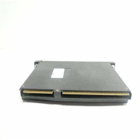
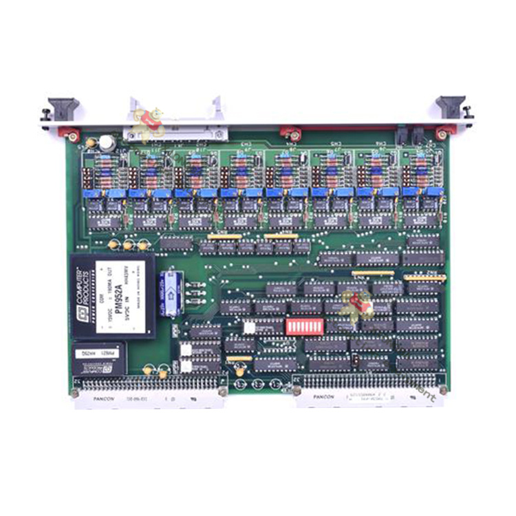
Isolated Analog Voltage/Current Input module IC695ALG106 provides 6 isolated input
channels.
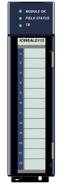
Isolated Analog Voltage/Current Input module IC695ALG112, shown at right, provides
12 input channels.
Analog input channels can be configured for these ranges:
• Current: 0 to 20mA, 4 to 20mA, +/- 20mA
• Voltage: +/- 10V, 0 to 10V, +/- 5V, 0 to 5V, 1 to 5V
GE IC695ALG106 Isolated Analog Input Modules
These modules must be installed in an RX3i Universal Backplane. The modules require
the use of one front-mounted terminal block (ordered separately). Terminal blocks are
available in the following different styles:
• Box-style (IC694TBB032),
• Extended Box-style (IC694TBB132),
• Spring-style (IC694TBS032), and
• Extended Spring-style (IC694TBS132).
Extended terminal blocks provide the extra shroud depth needed for shielded wiring.
See GFK-2314, PACSystems RX3i System Manual, for more information about terminal
blocks.
Note: Terminal blocks for this module must be ordered separately.
Module Features
• Completely software-configurable, no module jumpers to set
• On-board error-checking
• Open-circuit detection for all voltage and 4-20mA inputs
• Configurable scaling and offsets per channel
• High alarm, low alarm, high-high alarm, low-low alarm detection and reporting
selectable per channel
• Module fault reporting
• Supports diagnostic point fault contacts in the logic program
• Flash memory for future upgrades
• Positive and negative Rate of Change Alarms
• Configurable interrupts for channel alarms and faults
• Terminal Block insertion or removal detection
• Hot-swappable— module may be inserted into or removed from a powered backplane
Specifications
Input Ranges Current: 0 to 20mA, 4 to 20mA, +/- 20mA
Voltage: +/- 10V, 0 to 10V, +/- 5V, 0 to 5V, 1 to 5V
Power Requirements
(from the backplane)
ALG106: 230 mA maximum @ 5.0V +5% / -2.5%,
320 mA maximum @ 3.3V +5% / -3%
ALG112 490 mA maximum @ 5.0V +5% / - 2.5%,
310 mA maximum @ 3.3V +5% / - 3%
Power Dissipation within Module IC695ALG106: 2.97 watts maximum; with 20mA inputs on all 6 channels
IC695ALG112: 4.89 watts maximum with 20mA inputs on all 12 channels
Thermal Derating No derating
Resolution 16 bit ADC converted to Floating Point or Integer
Input Data Format Configurable as floating point IEEE 32 bit or 16-bit integer in a 32-bit field
Filter Options 8Hz, 12Hz, 16Hz, 40Hz, 250Hz, 1000Hz
Input Impedance >500 Kohm voltage inputs
Current Input Resistance 250 ohms +/- 1%
Open Circuit Detection time 1 second maximum
Overvoltage +/-35 VDC continuous, maximum
Overcurrent +/-35mA continuous, maximum
Normal Mode Noise Rejection
(dB)
At 50Hz At 60Hz
8 Hz filter 90 75
12 Hz filter 75 80
16 Hz filter 35 75
Common Mode Noise Rejection 100dB minimum @ 50/60 Hz with 8 Hz filter
100dB minimum @ 50/60 Hz with 12 Hz filter
Channel-Channel DC Crosstalk -70 dB minimum
Isolation Voltage
terminal block to
backplane/chassis and
channel to channel
I-coupler, transformer isolated
250 VAC continuous/1500 VAC for 1 minute
Analog Step Change Response The analog input will settle to 0.1% of its final value within 1.7mS for a step
change on the input pins of the module. (Any digital filtering is in addition to
this time.)
Digital Filtering Settling Time
(milliseconds)
The settling time depends on the configured filter time.
8 Hz Filter: 127 mS
12 Hz Filter: 67 mS
16 Hz Filter: 56 mS
40 Hz Filter: 21 mS
250 Hz Filter: 3.1 mS
1000 Hz Filter: 0 mS (no digital filtering; analog front-end filter only)
Analog Module Scan Time
(milliseconds)
The modules provide a new sample every 1mS, regardless of the digital
filtering selected. See Digital Filtering Settling Time for the amount of time
required to have settled data.
Calibrated Accuracy 0.1% of range at 25°C
0.2% of range over entire temperature span
In the presence of severe RF interference (IC 801-3, 10V/M), accuracy
may be degraded by 2.0% of range.
Calibration Interval 12 months typical to meet accuracy specifications over time. Offset can be
applied as a periodic calibration adjustment.
Indicator Light Emitting Diodes (LEDs)
MODULE OK — indicates the module’s ability to perform normal operations.
Green, ON Module OK and configured
or Green or Amber, slow flashing Module OK but not configured.
Green, quick flashing Error
OFF Not OK: no backplane power present or module is defective
FIELD STATUS — indicates the status of the module’s field connections.
Green, ON No faults on any enabled channel, and Terminal Block is present
Amber, ON Fault on at least one channel
OFF Terminal block not present or not fully seated
TB — indicates the status of the module’s connection to its terminal block.
Green, ON Terminal block present
Red, ON Terminal block not present or not fully seated
OFF No backplane power to module
Channel Diagnostic Data
The module can be configured to report channel diagnostics status data to the CPU. The CPU stores this data at the
module’s configured Diagnostic Reference Address. Use of this feature is optional. For details on module configuration,
refer to the PACSystems RX3i System Manual, GFK-2314.
The diagnostics data for each channel occupies 2 words whether the channel is used or not:
Bit Value Function
D0
0 Low alarm not Exceeded
1 Low alarm Fault
D1
0 High Alarm not Exceeded
1 High Alarm Exceeded
D2
0 Not Under Range
1 Under Range
D3
0 Not Over Range
1 Over Range
D4
0 No Open Wire
1 Open Wire
D5
0 No Short Circuit
1 Short Circuit
D6
0 Spare. Always set to zero
1 Invalid value.
D7
0 No extended diagnostic Information
1 See extended diagnostic Information in bits D8-D15.
D8-D15 — Extended diagnostic Information (refer to GFK-2314)
Purchase history
| User name | Member Level | Quantity | Specification | Purchase Date |
|---|
Total 0 Record
Customer Reviews
Satisfaction :
5 Stars
No evaluation information


-
 ABB molded case circuit breaker
 -
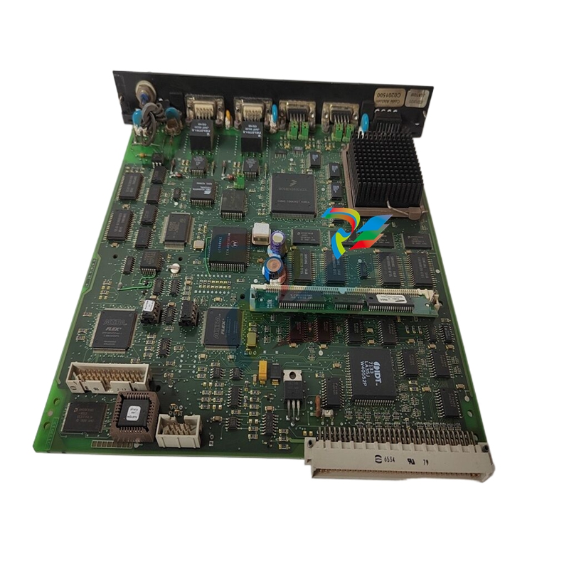
 ABB MVME162 Embedded Controller
 -
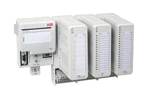 ABB TU810V1 System 800xA hardware selector
 -
 ABB SPAJ 140 C overcurrent and ground fault relay
 -
 ABB AC 800PEC High Performance Control System
 -
 ABB REF601 and REJ601 relays
 -
 ALSTOM RPH3/PS125b Controlled Switching Device,CT1VT220/TCR
 -
 ABB V-Contact VSC Medium voltage vacuum contactors
 -
 ABB 3BHE004385R0001 UNS 0884a, V1:Current Sensor 2000A
 -
 ABB UAD206A101 Programmable Logic Controller
 -
 ABB ACS800-04/U4 driver module
 -
 ABB UAD149A0011 3BHE014135R0011 Controller Module
 -
 ABB BSM series AC servo motor
 -
 ALSTOM DFI-150-0003- Limelight Diagnostic Board
 -
 ABB GCC960C102 motor driver
 -
 ABB INDUSTRIALDRIVES UCU-22, UCU-23 andUCU-24control units
 -
 ABB XDD501A101 Bus Terminal Module
 -
 ABB S800 I/O DTM 5.3 module
 -
 ALSTOM N897164611M High Performance Control Module
 -
 ALSTOM N897164610L Pulse Output Module
 -
 ALSTOM N70032702L High Performance Control Module
 -
 ALSTOM MVAJ1L1GB0771B Auxiliary Transmission Relay
 -
 GE 239 MOTOR PROTECTION RELAY
 -
 ALSTOM ADVANCED MICRO CONTROLLER 2
 -
 Honeywell HC900 Process and Safety Controller
 -
ABB ControlMaster CM10 Universal Process Controller
-
ABB dual power conversion switch
-
 ABB RET 541/543/545 Transformer Terminal Device
 -
 ABB Relion ® RET620 Transformer Protection and Control Device
 -
 ABB Relion ® REU615 Voltage Protection and Control Device
 -
 ABB Relion ® REU615 Voltage Protection and Control Device
 -
 ABB REX615 Protection and Control Relay Products
 -
ABB PGC2000 series E2 process gas chromatograph
-
 ABB PROCOLOR P 88QT03 bus coupling module
 -
 Honeywell WEB-8000 Controller
 -
 ABB Protection Relay REX 521
 -
 ABB 5SGY3545L0020 Controller Module
 -
 ABB 5SGY3545L0017 module tension controller
 -
ABB 5SGY3545L003 IGCT control module
-
ABB SNAT609TAI 5761789-6H Industrial I/O Interface Card
-
ABB SNAT602TAC circuit board
-
 ABB SNAT603 CNT Control Board
 -
ABB SNAT634PAC pulse amplifier module
-
 ABB RK682011-BA RL0B 100 standard unit module
 -
 ABB PP846A 3BSE042238R2 Industrial Control Panel
 -
 ABB ZMU-02 inverter memory card
 -
 ABB 3BHE014135R0011 UAD149A0011 DCS POSITIONING CONTROL MODULE
 -
ABB 3BHE014135R0011 UAD149 A00-0-11 I/O module
-
 ABB MEASUREMENT & ANALYTICS Web Tension Systems with Tension Electronics PFEA113
 -
 ABB GDD471A001 2UBA0022R0001 motor control module
 -
ABB UCD224A103 high-performance control module
-
 ABB PDD205A0121 control module
 -
 ABB PDD205A1121 3BHE02535R1211 processor module
 -
 ABB DSDX453 Digital Input/Output Module
 -
ABB DSPC454 controller module
-
 Woodward ESDR4 Current Differential Protection Relay
 -
 Siemens SIJECT CI16iP StepB 6AТ1131-6DF21-0AB0 Compact Control
 -
 EtherNet/IP™ to Remote I/O or DH+ Gateway AN-X2-AB-DHRIO
 -
ABB 81EU01-E/R3210 Analog Signal Input Module
-
 ABB TK457V050 Industrial Temperature Controller
 -
 ABB DSRF197K01 Control Module
 -
 ABB TK802F SD802F/SD812F power cord
 -
ABB 3BHE03930R0101 I/O module
-
ABB 3BHB0040277R0101 GVC700AE01 thyristor module
-
 ABB 3BHB003154R0101 5SXE05-0156 IGCT module
 -
 RELIANCE INSPECTOR VCIB-06 Advanced Industrial Visual Display
 -
ABB AO2000-LS25 Laser analyzer
-
 HIMA F8650X Central module
 -
ABB PM864AK01 Classic System 800xA hardware selector
-
 ABB 3BSE048845R1 CI868K01 IEC 61850 Interface
 -
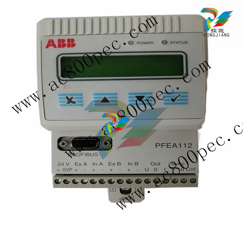 ABB 5SHY35L4520 Asymmetric Integrated Gate Converter Thyristor
 -
 ABB UNS0119A-P V101 3BHE029153R0101 processor module
 -
 Xycom 99212A-001 PC board
 -
 Xycom 144365-001 motherboard
 -
 XYCOM 70400-001 T3065-4 XVME-400 Board
 -
 Xycom Automation # 9450-2480016010000 Interface Monitor Model
 -
 XYCOM 70560-001 AIN XVME-560, VMEbus module card, PCB board
 -
 Xycom XVME-491 VMEbus 71491A PN70491-001
 -
 Xycom 99157-001 Circuit Board
 -
 Xycom 1341 egemin PM-070016 computer P/N 701301-01 TF-AEC-6910-C13
 -
 Xycom 8430 Industrial Controller Options 71338 115/230V P/N 8430-078122A002110
 -
 Xycom XVME-203 VME Digital Counter I/O Module Board PLC 70203-001
 -
ABB UNS0119A-P V101 Controller Module
-
 ABB GCC960C103 3BHE033067R0103 Controller Module
 -
 ABB GVC736CE101 High Performance AC Inverter
 -
 ABB PCD244A101 Terminal Card Module
 -
ABB 3BHE020356R0101 GFD212A motor thermal relay
-
ABB PDD500A101 power distribution module
-
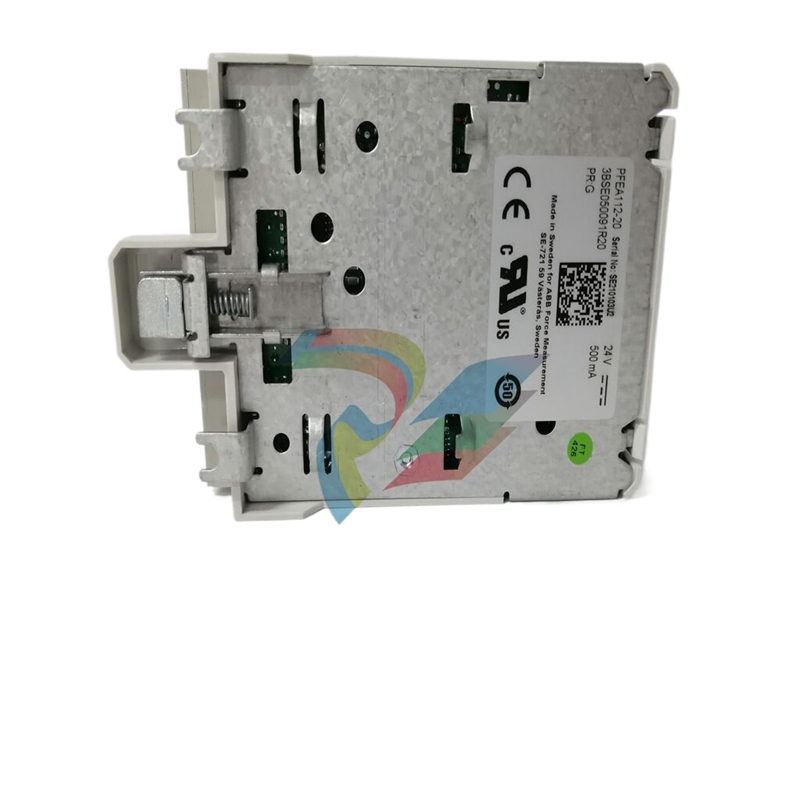 ABB PDD200A101 Industrial Control Module
 -
 Xycom 86863BA Control Card 86864-003/B
 -
 Xycom XVME-240 Digitale I/O-Karte für industriellen Einsatz
 -
 Xycom 9450 PC/AT computer operator interface HMI screen display keyboard control
 -
 XYCOM XCME-540 Analog I/O Module VMEBUS 70540-001
 -
 XYCOM 9460 Touch Screen
 -
 Xycom Analog CDA XVME VME TI DSP SCSI I/O module sequence RS232 card board
 -
 ALSTOM MCGG62N1CB0753F Auxiliary Transmission Relay
 -
 ABB S3N 3P 150A Standard thermal-magnetic
 -
 ABB SPIET800 Ethernet CIU Transfer Module
 -
ABB SPAD 346 C3 Differential Protection
-
 ABB 15.04.2005 Instrument Transformer
 -
 ABB FPX86-9329-C High Performance Industrial Controller
 -
 ABB ARCOL 0346 Industrial Control Module
 -
ABB ARCOL 0338 Controller Module
-
ABB ARCOL 0339 Industrial Inverter
-
 ABB 969-54 New Automation Controller Module DCS PLC Module
 -
 ABB 5SDD1060F0001 diode disk module
 -
ABB 5SDF0860H0003 Gate Cut off Thyristor Module
-
 ABB KUC720AE01 Industrial High Frequency Control Module
 -
 ABB KUC720AE - High Performance Industrial Control Module
 -
ABB UFC718AE01 high-performance main circuit interface
-
 ABB 5SHX2645L0004 Integrated Gate Converter Thyristor
 -
 Xycom 2000-KB1 94687-001 keyboard
 -
 Xycom 141452-001 5-slot amplifier card 141452001
 -
 Xycom 5015T/R2, Pro-face LCD 15" Monitor
 -
 Xycom 95212B-001 Module Circuit Board Card 95213-007 8503 PCB PWA Programmable Logic Controller
 -
 Xycom XVME-957 71957C-001 Circuit Board
 -
 XYCOM 99157-001 Circuit Board
 -
 Xycom 4115 T Operator Interface Panel 100-240v-ac
 -
 Xycom 2005 CRT Direct REPLACMENT LCD with Cable Kit
 -
 Xycom 4850 LCD monitor upgrade with cable kit 12 inches
 -
 Xycom 4810A 9-inch CRT LCD monitor upgrade
 -
ABB KOFA12D3 Indoor current transformers
-
.jpg) WOODWARD ProAct Positioner (Flex I/O)
WOODWARD ProAct Positioner (Flex I/O) -
.jpg) WOODWARD ProAct Positioner (16 pin), 3rd Generation
WOODWARD ProAct Positioner (16 pin), 3rd Generation -
 WOODWARD ProAct 75 Speed Control ( 1st Generation)
 -
.jpg) WOODWARD R-Series Actuators
WOODWARD R-Series Actuators -
.jpg) WOODWARD F-Series Positioners
WOODWARD F-Series Positioners -
 WOODWARD DVP Digital Valve Positioner

