
K-WANG
+086-15305925923
Service expert in industrial control field!


Product
Article
NameDescriptionContent
Adequate Inventory, Timely Service
pursuit of excellence


Ship control system
Equipment control system
Power monitoring system
Brand
Product parameters
- Telephone:+86-15305925923
- contacts:Mr.Wang
- Email:wang@kongjiangauto.com
Description
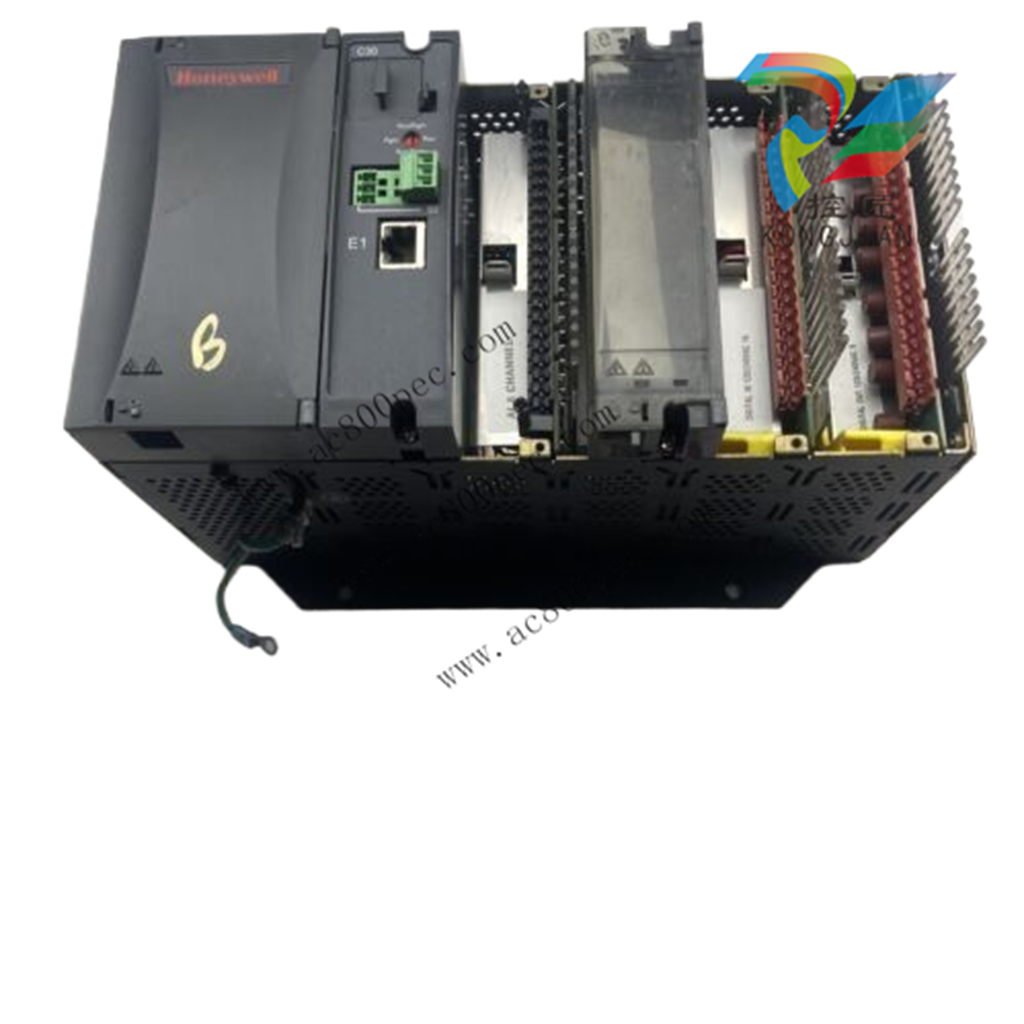
Note: The HC900 is equipped with an Ethernet port as a standard feature (two Ethernet ports on the C70
& C75 CPU). These ports can function simultaneously as slave and master communications ports.
The dual Ethernet ports (C70 & C75 CPU’s) can be configured for redundant operation to a host.
If the host device does not have the inherent capability to recognize a network failover, the
Honeywell HWIOPC Server would be used to perform this functionality.
Honeywell Pulse/Freq/Quad (4chan, 1Quad)900K01-0201
Note: The HC900 is equipped with an Ethernet port as a standard feature (two Ethernet ports on the C70& C75 CPU). These ports can function simultaneously as slave and master communications ports.
The dual Ethernet ports (C70 & C75 CPU’s) can be configured for redundant operation to a host.
If the host device does not have the inherent capability to recognize a network failover, the
Honeywell HWIOPC Server would be used to perform this functionality.
The dual Ethernet ports will not operate in a redundant configuration through a gateway to a
Host / server on another subnet. While both the E1 & E2 Ethernet can be configured with a default
Gateway address, only the E1 port will actually communicate across a gateway to another subnet
Hardware Components
This section contains general descriptions of each of the major components of the HC900 system.
For environmental specifications, refer to the section on Pre-Installation Planning.
HC900 Controller Rack
An HC900 Controller ("local rack") is shown in the following figure. As indicated in this figure, the Controller Rack
includes:
1. Rack, available in 4- 8-, or 12-slot versions
2. Power Supply
3. Controller Module
4. Grounding bars (for I/O wiring; optional)
5. Input/Output modules.
6. I/O Terminal Blocks
HC900 Redundant Controller Rack
A HC900 Redundant Controller is shown in the following figure.
1. Rack
2. Redundancy Switch Module (RSM) . Interface between Lead/Reserve controllers.
3. Lead/Reserve controllers. Two C75 CPUs, designated “CPU-A” (left), “CPU-B” (right).
4. Two 900P01-xxxx or 900P02-xxxx Power Supplies.
I/O Expansion Rack
I/O expansion ("remote") racks, shown in Figure 8, are available to accommodate additional input/output modules,
and/or to enable location of I/O modules close to the process and remote from the controller. For C75/C75S, all I/O
is in a rack or racks separate from the controller rack.
Scanner type must match controller type. i.e. example S50S may only be used with C50S, or C70S. S50S cannot be
used with a C50 or C70.
An I/O expansion rack includes:
1.Rack, available in 4- 8-, or 12-slot versions
2. Power Supply
3. Scanner 1 Module (S50/S50S) (shown) or Scanner 2 Module (S75/S75S)
4. Grounding bars (for I/O wiring; optional; required for
safety applications)
5.Input/Output modules
6.I/O Terminal Blocks
7. Power Status Module (PSM)
(req’d if using Reserve Power Supply)
8.Reserve Power Supply (optional). Available in 8- or 12-
slot racks.
Rack Options
Racks are available in 4-slot, 8-slot, and 12-Slot versions. Racks are interchangeable between the Controller rack
and an I/O expansion rack, and all three versions shown in the following figure are available for either purpose.
8 and 12 slot I/O racks can be modified with additional slots for optional Reserve Power Supply and Power Status
Module.
Note: You can install redundant power on any 8 or 12 slot I/O rack
Power Supply
The P01 Power Supply, shown in Figure 10, provides 5 Vdc and 24 Vdc to the backplane connectors in the local and
remote racks. Power Supply is used in each Controller Rack, I/O expansion racks and for all rack versions (4-slot,
8-slot, and 12-Slot).
The lower capacity P02 power supply is available for reduced I/O applications and for Redundant Controller rack
power.
P24 power supply provides 5VDC and 24VDC to satisfy the power requirements of a single controller with I/O, a
Remote I/O rack or a Redundant C75 CPU. The 60 watt capacity requires minimal de-rating of the available HC900
I/O modules.
A tool-secured door covers the voltage connections. An internal non-replaceable fuse limits supply current under
certain fault conditions.
Each power supply includes an internal 5.0-amp fuse that
is not field-replaceable. (An external fuse may be added
by the user. See page 25)
Items shown with key numbers:
1. Voltage test points (P01model only)
2. AC/DC Input terminal block
3. Wiring label
4. Grounding lug (Reference; lug is not part of Power
Supply; it is staked to bottom of Rack.)
Power Status Module (PSM)
The Power Status Module (PSM) (Figure 11) sits between redundant power supplies on the
I/O rack (see page26). It is a status module for both power supplies and indicates which are
in use, PS-1 (left) or PS-2 (right) or both (typical).
When the status indicator for either or both of the power supplies is lit, it is reporting that the
status of the associated power supply is good and that the outputs are within specified
limits. When the status is off, either the power supply is off or the voltages are out of
tolerance.
Purchase history
| User name | Member Level | Quantity | Specification | Purchase Date |
|---|
Total 0 Record
Related products
Customer Reviews
Satisfaction :
5 Stars
No evaluation information


- other
- LTI Drives
- ADLINK
- Beckhoff
- Other Brands
- AMAT
- Iba
- PEPPERL+FUCHS
- Aerotech
- WATLOW
- MAN
- ADVANCED
- Abaco
- YOKOGAWA
- KOLLMORGEN
- MEGGITT
- kong-sberg
- METSO
- Motorola
- NI
- OEMAX
- RELIANCE
- scanlab
- schneider
- uniop
- Vibro-Meter
- Honeywell
- Rolls-Royce
- MOOG
- GE
- B&R
- Woodward
- Yaskawa
- xYCOM
- Siemens
- Emerson
- HIMA
- Bently
- ZYGO
- FOXBORO
- OMACO
- PROSOFT
- ENTERASYS
- TRICONEX
- Parker
- Lenze
- KEBA
- Alstom
- CTI
- ABB
- A-B
142

-
 ADLINK AmITX-ALN-N97 Mini ITX Industrial Motherboard
 -
 ADLINK NuPRO-850 Full length ePCI-X Industrial Control Board
 -
 ADLINK MI-965 Mini ITX Industrial Motherboard
 -
 ADLINK M-302 ATX Industrial Motherboard
 -
 ADLINK PXI-3920/PXI-3910 3U PXI System Controller
 -
 ADLINK PCI-8132 Two Axis Servo/Stepper Motion Control Card
 -
 ADLINK cPCI-6760D 6U CompactPCI Single Board Computer
 -
 ADLINK ACL-7122 144 bit digital I/O board
 -
 ADLINK NuPRO-775 Half length Socket370 Industrial Single Board Computer
 -
 ETEL Accuret MODULAR series servo controller
 -
 ADLINK PCI-9112/cPCI-9112 multifunctional acquisition card
 -
 ADLINK PCI-8102 Two Axis Pulse Motion Control Card
 -
 ADLINK PCI-9812/PCI-9810 synchronous 4-channel high-speed acquisition card
 -
 ADLINK PCI-7200/cPCI-7200 high-speed digital I/O board
 -
 ADLINK MXE-1000 series fanless embedded machine
 -
 ADLINK IMB-T10 Mini ITX Industrial Motherboard
 -
 ADLINK HSL Distributed High Speed I/O System
 -
 ADLINK PXI/DAQ/DAQe-2500 series multifunctional analog output DAQ card
 -
 ADLINK PXI/DAQ/DAQe-2200 series multifunctional data acquisition card
 -
 ADLINK ETX-AT ETX Core Computer Module
 -
 ADLINK ACL-7225 ISA 16 channel relay output+16 channel isolated digital input card
 -
 ADLINK DAQ-2000 series synchronous acquisition card
 -
 ADLINK NuPRO-E330 PICMG 1.3 full-length industrial motherboard (SHB)
 -
 ADLINK ACL-8112 series multifunctional ISA acquisition card
 -
 ADLINK USB-2405 24 bit dynamic signal acquisition module
 -
 ADLINK PXIS-3320 15 slot 6U PXI chassis
 -
 ADLINK PCIe GIE7x series acquisition card
 -
 ADLINK PCIe-7856/PCIe-7853 Distributed Motion and IO Main Controller PCIe Acquisition Card
 -
 ADLINK PCI-6308 series isolated analog output board
 -
 ADLINK PCI-7432 Isolated Digital I/O Acquisition Card
 -
 ADLINK NuPRO-E72 PICMG 1.3 Full length Industrial SHB Single Board Computer
 -
 ADLINK MXE-5400 series fanless embedded industrial computer
 -
 ADLINK M-322 Industrial ATX Motherboard
 -
 ADLINK IMB-M43H Industrial ATX Motherboard
 -
 ADLINK IMB-M42H Industrial ATX Motherboard
 -
 ADLINK i915GV-INA ATX motherboard
 -
 ADLINK ETX-NR667 Embedded ETX Standard Computer Module
 -
 ADLINK ETX-BT (PATA to SATA version) User Manual
 -
 ADLINK CM1-BT1 PC/104 Single Board Computer
 -
![ADLINK cPCI-8217 [R] 3U CompactPCI VGA/LCD Display Module](https://aosspic10001.websiteonline.cn/hkw632bc8/image/image_aJXQRn.png) ADLINK cPCI-8217 [R] 3U CompactPCI VGA/LCD Display Module
ADLINK cPCI-8217 [R] 3U CompactPCI VGA/LCD Display Module -
 ADLINK AmITX-SL-G Mini ITX Embedded Motherboard
 -
 ADLINK AmITX-AL-I ultra-thin Mini ITX industrial motherboard
 -
 ADLINK NuPRO-E315 Full length PICMG 1.3 Industrial SHB Single Board Computer
 -
 ADLINK NuPRO-842 Full length PICMG 1.0 PCI/ISA Industrial Single Board Computer
 -
 ADLINK NuPRO-900A PICMG 1.2 ePCI-X Dual Xeon Industrial System Motherboard (SHB)
 -
 ADLINK cPCI-6910 series 6U CompactPCI single board computer
 -
 ADLINK cPCI-6860A 6U CompactPCI dual core single board computer with cPCI-R6860A rear adapter board
 -
 ADLINK cPCI-8168 6U CompactPCI Eight Axis Motion Control Card
 -
 ADLINK NuPRO-E340 PICMG 1.3 Industrial SHB motherboard
 -
 ADLINK NuPRO-A40H Full length PICMG1.0 Industrial Single Board Computer (SBC)
 -
 ADLINK NuPRO-852 Full length PICMG1.0 Industrial Single Board Computer
 -
 ADLINK NuPRO-841 Full length Industrial SBC
 -
 ADLINK NuPRO-590/591/592 series Socket7 full-length industrial SBC
 -
 ADLINK MXE-5500 series fanless embedded industrial computer
 -
 ADLINK MXE-200/200i Fanless Embedded Machine
 -
 ADLINK cPCI-6770 series CompactPCI CPU board
 -
 ADLINK NuPRO-A301 standard PICMG 1.0 full-length industrial SBC single board computer
 -
 ADLINK NuPRO-965 PICMG 1.3 SHB Express Full length Industrial Motherboard
 -
 ADLINK NuPRO-935A Full length PICMG1.0 Industrial Single Board Computer
 -
 ADLINK NuPRO-865 Full length Single Board Computer
 -
 ADLINK NuPRO-840 DV/LV Full Length PICMG Industrial Single Board Computer
 -
 ADLINK NuPRO-770 series full-length industrial single board computer
 -
 ADLINK NuPRO-595 series half length Socket 7 industrial motherboard
 -
 ADLINK cPCI-6840 series 6U CompactPCI single board computer
 -
 Foxboro 43AP series pneumatic indicator controller (PSS 3-1B3 A)
 -
 ADLINK cPCI-3720 Series 3U Low Power CompactPCI Single Board Computer
 -
 ADLINK NuPRO-E47, PICMG 1.3 full-length industrial SHB system motherboard
 -
 ADLINK NuPRO-E43 PICMG 1.3 full-length system motherboard
 -
 ADLINK NuPRO-780 series full-length industrial CPU board
 -
 ADLINK cPCI-6965 series 6U CPCI single board computer
 -
 ADLINK USB/LPCI/LPCIe-3488A GPIB interface card
 -
 Rittal SK 3241.700 Blue e+Fan Filter Unit
 -
 ADLINK cPCI-8168 6U CompactPCI 8-Axis Motion Control Card
 -
 ADLINK PCIe PXIe-8638 PCIe to PXIe Bus Expansion Kit
 -
 ADLINK PCIe GIE7x series acquisition card
 -
 ADLINK PCIe-7396 96 96 channel TTL digital IO card
 -
 ADLINK PCI/MPC/PXI-8164 Three in One Motion Control Card
 -
 ADLINK PCI-8154 Four Axis Pulse Motion Control Card
 -
 ADLINK PCI-8134 Four Axis Servo/Stepper Motion Control Card
 -
 ADLINK NuPRO-E42 PICMG1.3 full-length SHB motherboard
 -
 ADLINK MXC-6600 series high-performance fanless extended industrial computer
 -
 ADLINK MXC-6000 series embedded industrial control computer
 -
 ADLINK MXC-2300 series fanless expandable embedded industrial computer
 -
 ADLINK MCM-204 Independent Ethernet DAQ User Manual
 -
 ADLINK MCM-100/102 Edge IoT Platform for Machine Condition Monitoring User’s Manual
 -
 ADLINK MXC-6400 series sixth generation Core Fanless Scalable Industrial Control Computer
 -
 ADLINK Matrix Full Series Fanless Embedded Industrial Control Computers
 -
 ADLINK GIE64+4-channel PoE Gigabit Vision Capture Card
 -
 Honeywell UMS Security System Troubleshooting Guide
 -
 Honeywell Expert Series-C I/O Module
 -
 ADLINK EOS-1200 Embedded Vision Host
 -
 ADLINK DLAP-5200 series high-performance fanless AI industrial computer
 -
 ADLINK DLAP-4000 series embedded industrial control computer
 -
 ADLINK Matrix MXC-2000 Series Fanless Industrial Control Computer Specification
 -
 ADLINK DAQ -/DAQE -/PXI-2000 Series Multi functional Synchronous Acquisition Card
 -
 ADLINK cPCI-6520 6U CompactPCI Single Board Computer
 -
 ADLINK CM1-86DX3 PC/104 Single Board Computer
 -
 Honeywell DC1000 series PID temperature controller
 -
 ALSTOM MiCOM C264 Modular Substation Controller
 -
 EMERSON AMS 2140 Mechanical Health Analyzer
 -
 ADLINK NuPRO-E320 PICMG1.3 Full length Industrial Motherboard
 -
 ADLINK NuPRO-800 Series Full length Industrial SBC User Manual
 -
 ADLINK NuPRO-598 Industrial Single Board Computer
 -
 ADLINK MXC-6300 Fanless Embedded Industrial Control Computer
 -
 ADLINK Express-BASE7 User Manual
 -
 ADLINK DLAP-211 Series Fanless Edge AI Platform Specification Manual
 -
 ADLINK PCI/LPCI/LPCIe/cPCI-723X series 32 channel isolated digital I/O card
 -
 ADLINK cPCI-6965 series 6U CompactPCI single board computer
 -
 ADLINK NuDAQ 7200 series high-speed digital I/O board
 -
 Linghua ADLINK DLAP Deep Learning Acceleration Platform Product Manual
 -
 DEIF TCM-2 thyristor control module
 -
 Installation Manual for DEIF MVR-200 Series Medium Voltage Protection Device
 -
 DEIF MDR-2 multifunctional differential relay
 -
 DEIF AOM-1 Analog Output Module
 -
 DEIF AGI 400 series industrial/marine touch screen
 -
 Installation Manual for DEIF BRW-1 Marine Wing Bridge Instrument
 -
 DEIF AGC200 Quick Start Guide
 -
 DEIF AGC Multi line 2 Generator Set ControllerProduct basic information
 -
 ABB SPA-ZC 400 Ethernet Gateway Installation and Debugging Manual
 -
 ABB REM 543/545 motor generator protection device
 -
 DEIF PPU 300 controller
 -
 DEIF Delomatic 4 Offshore/Ocean Platform Dedicated Generator Power Management System DM-4
 -
 DEIF Delomatic Modular Generator Set Integrated System
 -
 DEIF AGC-4 Mk II Generator Set Controller
 -
 DEIF AGC-4 diesel generator set integrated controller
 -
 DEIF Multi line 2 Series PPU Unit Power Management (PPM) Operation Manual
 -
 DEIF Multi line 2 V2.4X Installation Manual
 -
 Beckwith M-6280 Digital Capacitor Bank Controller

K-JIANG

Add: Jimei North Road, Jimei District, Xiamen, Fujian, China
Tell:+86-15305925923