
K-WANG
+086-15305925923
Service expert in industrial control field!
Product
Article
NameDescriptionContent
Adequate Inventory, Timely Service
pursuit of excellence


Ship control system
Equipment control system
Power monitoring system
Brand
Product parameters
- Telephone:+86-15305925923
- contacts:Mr.Wang
- Email:wang@kongjiangauto.com
Description
Operating range of rotary actuators:
The usable span is 90°, which must be entirely within the
measuring range, but does not necessarily need to run
symmetrically to the longitudinal axis.
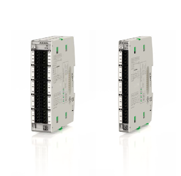
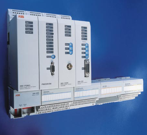
ABB 07EA90-SI Analog Input Unit
5 InstallationMechanical mounting
Operating range of rotary actuators:
The usable span is 90°, which must be entirely within the
measuring range, but does not necessarily need to run
symmetrically to the longitudinal axis. Note
During installation make sure that the actuator travel or rotation
angle for position feedback is implemented correctly.
Mounting on linear actuators
For mounting on a linear actuator in accordance with DIN / IEC
534 (lateral mounting as per NAMUR), the following attachment
kit is available:
M10413-01
1 Screw
2 Washer
3 Mounting bracket
4 Lever with follower pin
(for mechanical stroke
10 to 35 mm (0.39 to 1.38 in) or
20 to 100 mm (0.79 to 3.94 in)
5 Washers
6 Screws
7 U-bolts
8 Washers
9 Nuts
j Screws
k Spring washers
l Clamp plates
m Follower guide
Figure 6: Attachment kit
M10411-01
Figure 7: Attaching a follower guide to the actuator
1. Tighten the screws so that they are hand-tight.
2. Attach the follower guide 1 and clamp plates 2 with
screws 4 and spring washers 3 to the actuator stem.
M10409-01
Figure 8: Mounting lever and bracket on the positioner
1. Attach the lever 6 to the feedback shaft 5 of the
positioner (can only be mounted in one position due to the
cut shape of the feedback shaft).
2. Using the arrow marks 4, check whether the lever moves
within the operating range (between the arrows).
3. Hand-tighten the screw 7 on the lever.
4. Hold the prepared positioner (with the mount bracket 1 still
loose) on the actuator so that the follower pin for the lever
enters the follower guide to determine which tap holes on
the positioner must be used for the mount bracket.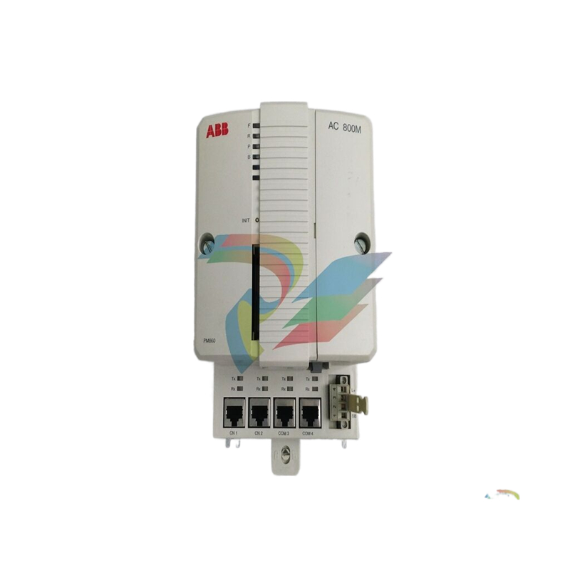
5. Secure the mount bracket 1 with screws 2 and washers 3
using the relevant tap holes on the positioner housing.
Tighten the screws as evenly as possible to ensure
subsequent linearity. Align the mount bracket in the oblong
hole to ensure that the operating range is symmetrical (lever
moves between the arrow marks 4).
M10418-01 2 1 4 3
Figure 9: Mounting on a cast iron yoke
1. Attach the mount bracket 2 with screw 4 and washer 3
to the cast iron yoke 1.
or
M10419-01 2 1 3 5 4
Figure 10: Mounting on a columnar yoke
1. Hold the mount bracket 3 in the proper position on the
columnar yoke 2.
2. Insert the U-bolts 1 from the inside of the columnar yoke 2
through the holes of the mount bracket.
3. Add the washers 4 and nuts 5.
Tighten the nuts so that they are hand-tight.
Note
Adjust the height of the positioner on the cast iron yoke or
columnar yoke until the lever is horizontal (based on a visual
check) at half stroke of the valve.
M10420-01
2 1
1 Increase linkage 2 Decrease linkage
Figure 11: Positioner linkage
The scale on the lever indicates the link points for the various
stroke ranges of the valve.
Move the bolt with the follower pin in the oblong hole of the
lever to adjust the stroke range of the valve to the working range
for the position sensor.
Moving the link point inwards increases the rotation angle of the
sensor. Moving the link point outwards reduces the rotation
angle of the sensor.
Adjust the actuator stroke to make use of as large an angle of
rotation as possible (symmetrical around the center position) on
the position sensor.
Recommended range for linear actuators:
• −28 to 28°
Minimum angle:
• 25°
Note
After mounting, check whether the positioner is operating within
the measuring range.
Purchase history
| User name | Member Level | Quantity | Specification | Purchase Date |
|---|
Total 0 Record
Related products
Customer Reviews
Satisfaction :
5 Stars
No evaluation information


KONG JIANG


Add: Jimei North Road, Jimei District, Xiamen, Fujian, China
Tell:+86-15305925923


