
K-WANG


- Telephone:+86-15305925923
- contacts:Mr.Wang
- Email:wang@kongjiangauto.com
This document describes the general specifications
of the FCN autonomous controller with NFCP501/
NFCP502 CPU module. (FCN is an acronym for field
control node.)
YOKOGAWA FCN Autonomous Controller Hardware (FCN-500)
Notation in this document:
• The term “FCN” refers to the module consisting type
autonomous controllers.
• The term “FCN-500” refers to the autonomous
controllers with NFCP501/NFCP502 CPU module.
For Function, refer to FCN Autonomous Controller
Functions (FCN-500), GS 34P02Q03-01E.
FCN Autonomous Controller
Hardware (FCN-500)
Yokogawa Electric Corporation
2-9-32. Nakacho, Musashino-shi, Tokyo, 180-8750 Japan
GS 34P02Q14-01E
GS 34P02Q14-01E
©Copyright Mar. 2016(YK)
20th Edition Apr. 1. 2022(YK)
FEATURES
• High-performance, high-reliability modular controller
• Memory with ECC
• Low heat dissipation eliminates the need for a fan
• A wealth of RAS features — CPU self-diagnostics, temperature monitoring, I/O diagnostics, and more
• The CPU, power supply module, internal communication bus on backboard (SB bus), E2 bus (extension bus), and
control network (Ethernet port 1 and 2) can all be duplexed, and all modules are hot-swappable. Use a couple of the
CPU module of the same type to make the CPU module duplex configuration.
• Can function as link active schedulers (LASs) for low-speed voltage mode (H1) FOUNDATION Fieldbus segments,
and link up FOUNDATION Fieldbus-enabled field devices.

CONFIGURATION
An FCN-500 consists of the following:
• Base module
• Power supply module
• CPU module
• E2 bus interface module (extending the unit) (*1)
• SB bus repeat module (extending the SB bus to connect an extension unit) (*1)
• I/O modules
*1: SB bus repeat module and E2 bus interface module can not be used together.
There are four types of base module.
- NFBU200 base module (long): Control unit and extension unit sharing,
duplexed power supply possibility
- N2BU051 base module (short): Control unit and extension unit sharing
- NFBU050 base module (short): Control unit only, for low power
- N2BU030 base module (compact): Control unit and extension unit sharing
l Control unit alone
The control unit is unit with CPU module. The maximum number of I/O modules that can be implemented depends on
the type of base module and the number of CPUs.
Maximum I/O Module Configurations
Base Module Unit Configuration Standard Duplexed (*1)
NFBU200 base module (long) Control unit alone Max. 8 modules Max. 6 modules
N2BU051 base module (short) Control unit alone Max. 3 modules Not applicable (*2)
NFBU050 base module (short) Control unit alone Max. 3 modules Not applicable (*2)
N2BU030 base module (compact) Control unit alone Max. 1 module Not applicable (*2)
*1: When CPU modules are duplexed
*2: Neither power supply nor CPU modules can be duplexed on N2BU051. NFBU050 or N2BU030.
Example: Standard control unit
F01E.ai
Unit:1 Slot 1 2 3 4 5 6 7 8 9 10
Ethernet
Example: Control unit with duplexed CPU and power supply modules
F02E.ai
1 Unit:1 Slot 2 3 4 5 6 7 8 9 10
Abbreviation Description
PWM Power supply module
CPU CPU module
IOM I/O module
N2EB E2 bus interface module
NFSB SB bus repeat module
DMY Dummy cover for power supply Module Slot
l Unit extension with E2 bus
Up to eight extension units can be connected to the control unit using the E2 bus interface modules. Two ports of
the E2 bus interface module mounted on the control unit can be connected to extension units as separate lines. The
maximum number of extendable units that can be connected is a maximum of 8 units in total of two lines. Three types
of base modules (NFBU200. N2BU051 or N2BU030) can be used as control unit and extension unit. By installing two
E2 bus interface modules in each base module, it is possible to duplex E2 bus. (*1)
Connect each E2 bus interface module with UTP straight cable (CAT 5e or higher). The distance between units can be
extended up to 100 m.
*1: When using the compact base module for the control unit, it is not possible to duplex the communication lines.
Maximum I/O Module Configurations
Base Module Unit Configuration Standard Duplexed (*1)
NFBU200 base module (long) Control unit with 8
extension units (*2) Max. 79 modules Max. 68 modules
Note: NFCP501/NFCP502 CPU module style S2 or later is required to use the E2 bus interface module.
*1: When CPU and E2 bus interface modules are duplexed.
*2: When NFBU200 base modules are used in all extension units.
Extension of Transmission distance by Optical fiber
The transmission distance between units can be extended by converting the system from UTP straight cable to
fiber optic cable with third party’s media converters. Only Layer 1 (Physical Layer) media converters which simply
convert packets from electric signal to optical signal can be used for the E2 bus. Refer to the verified media converter
information and precaution on Yokogawa Partner Portal STARDOM site when choosing the model.
Unit extension with SB bus
Up to two extension units can be connected using the SB bus repeat modules. The SB bus repeat module can be
mounted on the base module (NFBU200 only). By installing two SB bus repeat modules on each base module, it is
possible to duplex the SB bus. Connect each SB bus repeat module with a dedicated cable.
Maximum I/O Module Configurations
Base Module Unit Configuration Standard Duplexed (*1)
NFBU200 base module (long) Control unit with 2
extension units Max. 25 modules Max. 20 modules
*1: When CPU and SB bus repeat modules are duplexed.
Jul. 1. 2018-00
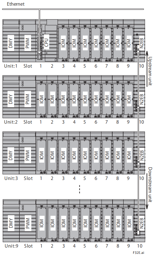
Example: Standard control unit + 2 extension units
with SB bus reprat modules
F03E.ai
Ethernet
Unit:1 Slot 1 2 3 4 5 6 7 8 9 10
Unit:2 Slot 1 2 3 4 5 6 7 8 9 10
Unit:3 Slot 1 2 3 4 5 6 7 8 9 10
Example: Control unit with duplexed CPU
modules, power supply modules, and SB bus + 2
extension units
Note: The CPU module, power supply module, and
SB bus can be made duplex individually, when
required.
| User name | Member Level | Quantity | Specification | Purchase Date |
|---|


- other
- LTI Drives
- ADLINK
- Beckhoff
- Other Brands
- AMAT
- Iba
- PEPPERL+FUCHS
- Aerotech
- WATLOW
- MAN
- ADVANCED
- Abaco
- YOKOGAWA
- KOLLMORGEN
- MEGGITT
- kong-sberg
- METSO
- Motorola
- NI
- OEMAX
- RELIANCE
- scanlab
- schneider
- uniop
- Vibro-Meter
- Honeywell
- Rolls-Royce
- MOOG
- GE
- B&R
- Woodward
- Yaskawa
- xYCOM
- Siemens
- Emerson
- HIMA
- Bently
- ZYGO
- FOXBORO
- OMACO
- PROSOFT
- ENTERASYS
- TRICONEX
- Parker
- Lenze
- KEBA
- Alstom
- CTI
- ABB
- A-B

-
 ADLINK PCI-9112/cPCI-9112 multifunctional acquisition card
 -
 ADLINK PCI-8102 Two Axis Pulse Motion Control Card
 -
 ADLINK PCI-9812/PCI-9810 synchronous 4-channel high-speed acquisition card
 -
 ADLINK PCI-7200/cPCI-7200 high-speed digital I/O board
 -
 ADLINK MXE-1000 series fanless embedded machine
 -
 ADLINK IMB-T10 Mini ITX Industrial Motherboard
 -
 ADLINK HSL Distributed High Speed I/O System
 -
 ADLINK PXI/DAQ/DAQe-2500 series multifunctional analog output DAQ card
 -
 ADLINK PXI/DAQ/DAQe-2200 series multifunctional data acquisition card
 -
 ADLINK ETX-AT ETX Core Computer Module
 -
 ADLINK ACL-7225 ISA 16 channel relay output+16 channel isolated digital input card
 -
 ADLINK DAQ-2000 series synchronous acquisition card
 -
 ADLINK NuPRO-E330 PICMG 1.3 full-length industrial motherboard (SHB)
 -
 ADLINK ACL-8112 series multifunctional ISA acquisition card
 -
 ADLINK USB-2405 24 bit dynamic signal acquisition module
 -
 ADLINK PXIS-3320 15 slot 6U PXI chassis
 -
 ADLINK PCIe GIE7x series acquisition card
 -
 ADLINK PCIe-7856/PCIe-7853 Distributed Motion and IO Main Controller PCIe Acquisition Card
 -
 ADLINK PCI-6308 series isolated analog output board
 -
 ADLINK PCI-7432 Isolated Digital I/O Acquisition Card
 -
 ADLINK NuPRO-E72 PICMG 1.3 Full length Industrial SHB Single Board Computer
 -
 ADLINK MXE-5400 series fanless embedded industrial computer
 -
 ADLINK M-322 Industrial ATX Motherboard
 -
 ADLINK IMB-M43H Industrial ATX Motherboard
 -
 ADLINK IMB-M42H Industrial ATX Motherboard
 -
 ADLINK i915GV-INA ATX motherboard
 -
 ADLINK ETX-NR667 Embedded ETX Standard Computer Module
 -
 ADLINK ETX-BT (PATA to SATA version) User Manual
 -
 ADLINK CM1-BT1 PC/104 Single Board Computer
 -
![ADLINK cPCI-8217 [R] 3U CompactPCI VGA/LCD Display Module](https://aosspic10001.websiteonline.cn/hkw632bc8/image/image_aJXQRn.png) ADLINK cPCI-8217 [R] 3U CompactPCI VGA/LCD Display Module
ADLINK cPCI-8217 [R] 3U CompactPCI VGA/LCD Display Module -
 ADLINK AmITX-SL-G Mini ITX Embedded Motherboard
 -
 ADLINK AmITX-AL-I ultra-thin Mini ITX industrial motherboard
 -
 ADLINK NuPRO-E315 Full length PICMG 1.3 Industrial SHB Single Board Computer
 -
 ADLINK NuPRO-842 Full length PICMG 1.0 PCI/ISA Industrial Single Board Computer
 -
 ADLINK NuPRO-900A PICMG 1.2 ePCI-X Dual Xeon Industrial System Motherboard (SHB)
 -
 ADLINK cPCI-6910 series 6U CompactPCI single board computer
 -
 ADLINK cPCI-6860A 6U CompactPCI dual core single board computer with cPCI-R6860A rear adapter board
 -
 ADLINK cPCI-8168 6U CompactPCI Eight Axis Motion Control Card
 -
 ADLINK NuPRO-E340 PICMG 1.3 Industrial SHB motherboard
 -
 ADLINK NuPRO-A40H Full length PICMG1.0 Industrial Single Board Computer (SBC)
 -
 ADLINK NuPRO-852 Full length PICMG1.0 Industrial Single Board Computer
 -
 ADLINK NuPRO-841 Full length Industrial SBC
 -
 ADLINK NuPRO-590/591/592 series Socket7 full-length industrial SBC
 -
 ADLINK MXE-5500 series fanless embedded industrial computer
 -
 ADLINK MXE-200/200i Fanless Embedded Machine
 -
 ADLINK cPCI-6770 series CompactPCI CPU board
 -
 ADLINK NuPRO-A301 standard PICMG 1.0 full-length industrial SBC single board computer
 -
 ADLINK NuPRO-965 PICMG 1.3 SHB Express Full length Industrial Motherboard
 -
 ADLINK NuPRO-935A Full length PICMG1.0 Industrial Single Board Computer
 -
 ADLINK NuPRO-865 Full length Single Board Computer
 -
 ADLINK NuPRO-840 DV/LV Full Length PICMG Industrial Single Board Computer
 -
 ADLINK NuPRO-770 series full-length industrial single board computer
 -
 ADLINK NuPRO-595 series half length Socket 7 industrial motherboard
 -
 ADLINK cPCI-6840 series 6U CompactPCI single board computer
 -
 Foxboro 43AP series pneumatic indicator controller (PSS 3-1B3 A)
 -
 ADLINK cPCI-3720 Series 3U Low Power CompactPCI Single Board Computer
 -
 ADLINK NuPRO-E47, PICMG 1.3 full-length industrial SHB system motherboard
 -
 ADLINK NuPRO-E43 PICMG 1.3 full-length system motherboard
 -
 ADLINK NuPRO-780 series full-length industrial CPU board
 -
 ADLINK cPCI-6965 series 6U CPCI single board computer
 -
 ADLINK USB/LPCI/LPCIe-3488A GPIB interface card
 -
 Rittal SK 3241.700 Blue e+Fan Filter Unit
 -
 ADLINK cPCI-8168 6U CompactPCI 8-Axis Motion Control Card
 -
 ADLINK PCIe PXIe-8638 PCIe to PXIe Bus Expansion Kit
 -
 ADLINK PCIe GIE7x series acquisition card
 -
 ADLINK PCIe-7396 96 96 channel TTL digital IO card
 -
 ADLINK PCI/MPC/PXI-8164 Three in One Motion Control Card
 -
 ADLINK PCI-8154 Four Axis Pulse Motion Control Card
 -
 ADLINK PCI-8134 Four Axis Servo/Stepper Motion Control Card
 -
 ADLINK NuPRO-E42 PICMG1.3 full-length SHB motherboard
 -
 ADLINK MXC-6600 series high-performance fanless extended industrial computer
 -
 ADLINK MXC-6000 series embedded industrial control computer
 -
 ADLINK MXC-2300 series fanless expandable embedded industrial computer
 -
 ADLINK MCM-204 Independent Ethernet DAQ User Manual
 -
 ADLINK MCM-100/102 Edge IoT Platform for Machine Condition Monitoring User’s Manual
 -
 ADLINK MXC-6400 series sixth generation Core Fanless Scalable Industrial Control Computer
 -
 ADLINK Matrix Full Series Fanless Embedded Industrial Control Computers
 -
 ADLINK GIE64+4-channel PoE Gigabit Vision Capture Card
 -
 Honeywell UMS Security System Troubleshooting Guide
 -
 Honeywell Expert Series-C I/O Module
 -
 ADLINK EOS-1200 Embedded Vision Host
 -
 ADLINK DLAP-5200 series high-performance fanless AI industrial computer
 -
 ADLINK DLAP-4000 series embedded industrial control computer
 -
 ADLINK Matrix MXC-2000 Series Fanless Industrial Control Computer Specification
 -
 ADLINK DAQ -/DAQE -/PXI-2000 Series Multi functional Synchronous Acquisition Card
 -
 ADLINK cPCI-6520 6U CompactPCI Single Board Computer
 -
 ADLINK CM1-86DX3 PC/104 Single Board Computer
 -
 Honeywell DC1000 series PID temperature controller
 -
 ALSTOM MiCOM C264 Modular Substation Controller
 -
 EMERSON AMS 2140 Mechanical Health Analyzer
 -
 ADLINK NuPRO-E320 PICMG1.3 Full length Industrial Motherboard
 -
 ADLINK NuPRO-800 Series Full length Industrial SBC User Manual
 -
 ADLINK NuPRO-598 Industrial Single Board Computer
 -
 ADLINK MXC-6300 Fanless Embedded Industrial Control Computer
 -
 ADLINK Express-BASE7 User Manual
 -
 ADLINK DLAP-211 Series Fanless Edge AI Platform Specification Manual
 -
 ADLINK PCI/LPCI/LPCIe/cPCI-723X series 32 channel isolated digital I/O card
 -
 ADLINK cPCI-6965 series 6U CompactPCI single board computer
 -
 ADLINK NuDAQ 7200 series high-speed digital I/O board
 -
 Linghua ADLINK DLAP Deep Learning Acceleration Platform Product Manual
 -
 DEIF TCM-2 thyristor control module
 -
 Installation Manual for DEIF MVR-200 Series Medium Voltage Protection Device
 -
 DEIF MDR-2 multifunctional differential relay
 -
 DEIF AOM-1 Analog Output Module
 -
 DEIF AGI 400 series industrial/marine touch screen
 -
 Installation Manual for DEIF BRW-1 Marine Wing Bridge Instrument
 -
 DEIF AGC200 Quick Start Guide
 -
 DEIF AGC Multi line 2 Generator Set ControllerProduct basic information
 -
 ABB SPA-ZC 400 Ethernet Gateway Installation and Debugging Manual
 -
 ABB REM 543/545 motor generator protection device
 -
 DEIF PPU 300 controller
 -
 DEIF Delomatic 4 Offshore/Ocean Platform Dedicated Generator Power Management System DM-4
 -
 DEIF Delomatic Modular Generator Set Integrated System
 -
 DEIF AGC-4 Mk II Generator Set Controller
 -
 DEIF AGC-4 diesel generator set integrated controller
 -
 DEIF Multi line 2 Series PPU Unit Power Management (PPM) Operation Manual
 -
 DEIF Multi line 2 V2.4X Installation Manual
 -
 Beckwith M-6280 Digital Capacitor Bank Controller
 -
 Beckwith M-3311 Transformer Protection Relay
 -
 Beckwith M-3311A Transformer Integrated Protection Device
 -
 Beckwith M-3310 Transformer Integrated Protection Device Specification
 -
 Beckwith M-0359 Syncrocloser Check Plus Application Guide for Synchronous Calibration Relay
 -
 Beckwith M-0293A On Load Tap changer Controller Application Guide
 -
 DEIF GPU-3 Synchronous/Asynchronous Generator Integrated Microcomputer Protection Controller
 -
 Installation Instructions for DEIF PPM-3
 -
 Beckwith M-3520 distributed power grid connected comprehensive protection device
 -
 Beckwith M-3430 generator comprehensive protection device
 -
 Beckwith M-2293B adapter panel

K-JIANG

Add: Jimei North Road, Jimei District, Xiamen, Fujian, China
Tell:+86-15305925923