K-WANG

+086-15305925923
Service expert in industrial control field!
NameDescriptionContent
Adequate Inventory, Timely Service
pursuit of excellence 
Ship control system
Equipment control system
Power monitoring system
Current position:
   
Brand
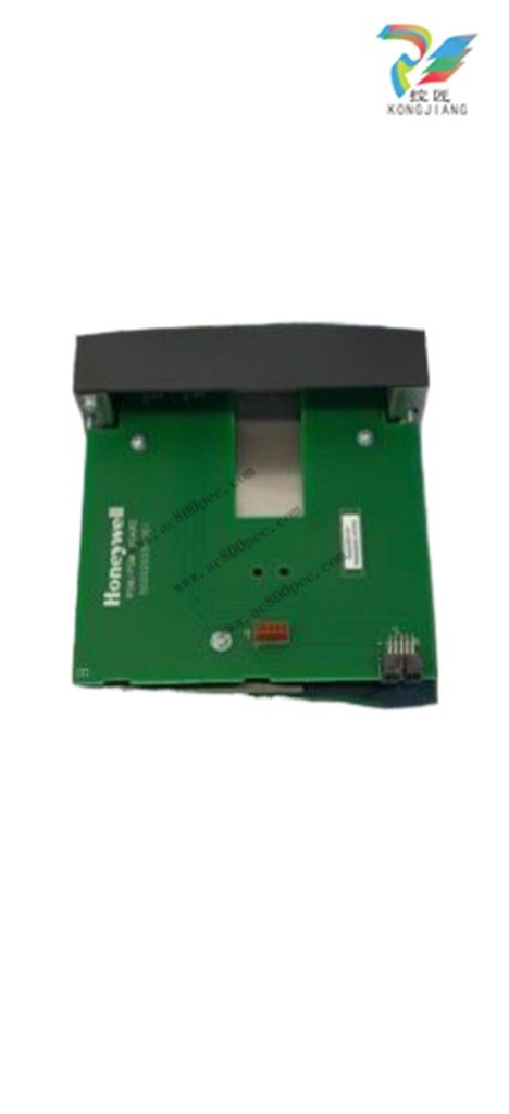
Honeywell Low Votage RTP Cable (5.0M, 16.4ft.) Note 6 (NOT FOR SIL2 SYSTEMS) 900RTC-L150
❤ Add to collection

Honeywell Low Votage RTP Cable (5.0M, 16.4ft.) Note 6 (NOT FOR SIL2 SYSTEMS) 900RTC-L150

+86-15305925923
Mr.Wang
wang@kongjiangauto.com

Set scanner address for the I/O rack

using the Scanner Module DIP

switches on SW3 (shown at right). For

C50/C70, use addresses 1-11. For

C75, use addresses 1-12.

11500.00
¥11500.00
Weight:3.550KG
Quantity:
(Inventory: 15)
Consultation
Accessories
  • ABB-07AC91-Analo
    Original :¥16475.00
    With a price :¥16475
    Quantity  
  • ABB-AC31 91serie
    Original :¥16475.00
    With a price :¥16475
    Quantity  
  •   
    Original :¥
    0.00
      
      With the total price :¥
    0.00
Product parameters
  • Telephone:+86-15305925923
  • contacts:Mr.Wang
  • Email:wang@kongjiangauto.com
Description

Set scanner address for the I/O rack

using the Scanner Module DIP

switches on SW3 (shown at right). For

C50/C70, use addresses 1-11. For

C75, use addresses 1-12.


Honeywell Low Votage RTP Cable (5.0M, 16.4ft.) Note 6 (NOT FOR SIL2 SYSTEMS) 900RTC-L150

Set scanner address for the I/O rack
using the Scanner Module DIP
switches on SW3 (shown at right). For
C50/C70, use addresses 1-11. For
C75, use addresses 1-12.
Scheme 1 (upto 5 racks):
DIP switches 6-8 must be OFF. Only
one DIP switch may be ON:
DIP switch 1 ON = Scanner 1
DIP switch 2 ON = Scanner 2
DIP switch 3 ON = Scanner 3
DIP switch 4 ON = Scanner 4
DIP switch 5 ON = Scanner 5
Scheme 2 (upto 12 racks):
DIP switch 6 NO Always and
1 ON = Scanner 1
2 ON = Scanner 2
2 & 1 ON = Scanner 3
3 ON = Scanner 4
3 & 1 ON = Scanner 5
3 & 2 ON = Scanner 6
3 & 2 & 1 ON = Scanner 7
4 ON = Scanner 8
4 & 1 ON = Scanner 9
4 & 2 ON = Scanner 10
4 & 2 & 1 ON = Scanner 11
4 & 3 ON = Scanner 12
A small slotted screwdriver or
paperclip works well; avoid pencils.
4 Repeat steps 1 through 3 for each I/O
expansion rack.
Then, for each I/O expansion rack,
insert the Scanner Module
immediately to the right of the Power
Supply, and secure it in place with the
two captured screws in the faceplate.
Step Procedure Comments/References

5 I/O will be installed later. See Page 78.
I/O Module Installation and Wiring

Overview
This section contains descriptions of and procedures for installing I/O Modules in controller racks
(C30/C30S, C50/C50S, C70/C70S, models) and in I/O expansion racks (S50/S50S, S75/S75S only).
Module Placement in Racks
Each input or output module is placed in an I/O slot in a rack as shown in Figure 37.
Each “slot” in a rack includes a set of guides that locate the circuit board in the rack and a 20-pin (4 x 5)
socket in the backplane that receives the associated 4 x 5-pin plug at the back of the I/O module.
At the front of each I/O module, a 20 or 36 pin plug receives the associated socket on the back of a terminal
block. When the I/O module is inserted into the rack and the terminal block is placed on the circuit board,
two captured screws in the terminal block are fastened to metal tabs on the rack.
Figure 37 – I/O Module Installation
 Do not use an input/output terminal block if the terminal block is damaged, if the door is
missing, or if one or both mounting screws are missing.
 Always tighten both terminal block screws to proper torque settings before applying field
power to the module. Torque to 0,4 - 0,5 Nm (3.5 – 4.4 Lb-In.)
 Do not apply energized (“live”) field wiring to an input/output module that is not installed in
one of the racks in the HC900 Controller.
 Do not operate the controller without a Protective Earth connection.
Failure to comply with these instructions could result in death or serious injury.

Terminal Block Styles
The terminal block is available in the barrier style, shown at
left in Figure 38, and the Euro style, shown at right. Not
shown: a Euro style with 36 connections is also available
for certain high capacity modules.
Terminal blocks have an embossed numbering “key” that
shows the numbering pattern of the 20/36 connections.
The frame associated with the terminal block has a
transparent hinged door. The hinged door is a tool secured
cover. To open the door, insert a flat screwdriver into the
slot at the top and bottom of the door while pulling out. The
door has molded-in tabs that hold labels, which are uniquely
color-coded to identify each module type.
Each label is printed on both sides. On the front (visible
when the door is closed) are I/O channel numbers, with
spaces in which tag names can be written. On the back
(visible when the door is open) are wiring patterns for the
type of module located in the slot.
Figure 38 – Terminal Block Styles
The 20-pin, inline connectors at the back of the terminal blocks are universal; that is, any type of I/O
module can be used with either the Barrier style or the Euro style terminal block. The 36-pin Euro terminal
blocks must be used with High Level AI, High Level AO, 32 DI, and 32 DO modules.
ATTENTION
Before mounting terminal blocks in the rack, be sure they are properly keyed to the
module type they will be used with. See I/O Module Installation Procedures, page 84.
Terminal Block Colors and Keying
Both the barrier style and the Euro style are available in two colors (red and black). Black terminal blocks,
which have gold contacts, are used for low-voltage, low-energy signals such as analog inputs, contact
inputs and low DC voltages. Red terminal blocks, which have tin contacts, are used for higher voltages
such as 120/240 Vac.
Colors of each Terminal Blocks must correlate to that of the mating header on I/O modules with which they
are used; that is:
 Black terminal blocks, which have gold contacts, are for use with I/O modules that have black headers
and gold pins in the 20-pin connector; these include: Analog Input, 4-channel Analog Output, DC Input,
DC Output, Contact Input, Pulse Input, Pulse Output, Frequency Input, Quadrature Input.
 Red terminal blocks, which have white (tin) contacts, are for use with I/O modules that have red headers
and white- (tin-) contacts in the 20-pin connector; these include: AC Input, AC Output, and Relay
Output.
 36-pin black Euro terminal blocks, which have gold contacts, are for use with 8-point AO, 16-point AO,
16-point AI, 32-point DI, and 32-point DO modules.
 Terminal blocks must be keyed by the installer to prevent high voltage terminal blocks from being
installed on low voltage modules. See Table 14.
 Any of the color-coded labels will fit into the door of any terminal block. Use care to ensure that all
hardware components match each other, and also match the control strategy in the configuration file.
  • AB PLC-5 1771 to ControlLogix 1756 I/O Wiring Conversion Systems
  • AB Analog Input Module Cat. No. 1771-IFE
  • AB 1771-IFE A/B/C Analog Input Module
  • AB Cat. No.1771-IVN DC (10-30V) Input Module
  • AB 1771-OFE Series B Analogue Output Modules
  • AB Cat. No.1771-QB Linear Positioning Module
  • AB 1771-VHSC Very High-speed Counter Module
  • AB 1771 Digital I/O AC Input and Output Modules
  • AB 1783 Series Ethernet Taps
  • AB Stratix 8000 and 8300 Ethernet Managed Switches
  • AB MicroLogix 1400 Programmable Controllers
  • AB1642 Module Manual MicroLogix 1500 & CompactLogix Resolver Interface Module
  • AB 1769-L24ER-QB1B CompactLogix 5370 L2 Controllers
  • AB 1769 Compact I/O Modules Specifications
  • AB 1769 Controller CompactLogix System
  • AB 1763-L16AWA MicroLogix 1100 Programmable Controller
  • AB 1763-L16AWA MicroLogix 1100 Programmable Controllers
  • AB 1762-L24AWA MicroLogix 1200 Programmable Controllers
  • AB 1762-IQ8OW6 DC-Input/Relay-Output Combination Module
  • AB 1757-SRM ProcessLogix and ControlLogix System Redundancy Module
  • GE ALSTOM:SPU.232.2.029.366.817
  • AB ProcessLogix R500.1 Process Control System
  • AB 1761 - NET - Ethernet Interface for ENI MicroLogix
  • AB 1761-L20BWB-5A MicroLogix 1000 Series
  • AB 1761 MicroLogix 1000 Programmable Controller
  • AB 1756-DHRIO, 1756-DHRIOXT ControlLogix Data Highway Plus-Remote I/O Communication Interface Module
  • AB 1756-D IO ControlLogix I/O Modules Specifications
  • AB 1756-cpu ControlLogix Systems
  • AB 1756 ControlLogix Analog I/O Modules
  • AB 1756 ControlLogix System
  • AB 1756 IB32 ControlLogix 32-point DC (10…31.2V) Input Module Series B
  • AB 1756-IR6I ControlLogix Analog I/O Modules
  • AB 1756-DNB ControlLogix DeviceNet Scanner Module
  • AB 1756-CN2RXT ControlLogix-XT ControlNet Interface Module
  • AB 1756-CN2 1756-CN2R ControlLogix ControlNet Interface Module
  • AB 1747 - AENTR SLC 500 EtherNet/IP Adapter
  • AB 1746, 1747SLC500 Control System Selection Guide
  • AB 1746-C7, 1746-C9, 1746-C16 SLC 500™ Programmable Controller Rack Interconnect Cables
  • AB 1746-BTM Drum Temperature Control Module
  • AB 1746-BAS and 1746-BAS-T SLC 500 BASIC and BASIC-T Modules
  • AB 1746-A4, -A7, -A10 SLC 500™ Modular Chassis
  • AB SLC 500™ Modular Chassis 1746-A4, -A7, -A10 and -A13 Series B
  • AB 1734-AENT POINT I/O EtherNet/IP Adapter
  • AB Allen-Bradley's 1734 POINT I/O Series Products
  • A-B 1715 Redundant I/O System Specifications
  • AB 56AMXN/B ControlLogix AutoMax DCSNet and AutoMax Remote I/O Communication Interface Module
  • AB Bulletin 1203 Serial Communications Module
  • AB 1326AB High Performance AC Servomotors
  • AB 1326AB 460V, Torque Plus Series, AC Servo Motors
  • AB 1336 PLUS II Engineering Drives
  • AB CENTERLINE® 2100/2400 Series Motor Control Centres
  • AB 1394 Digital AC Multi-Axis Motion Control System
  • AB 1398 ULTRA 100 Series Drives
  • AB 1402 Series Line Synchronisation Modules
  • AB 1407-CGCM Combined Generator Control Module
  • ABB 3BUS094398 IndustrialIT System 800xA Harmony/INFI90 System
  • ABB 3BUS092084R0001 IndustrialIT System 800xA Symphony Harmony
  • ABB AC 800M 3BSE036352 Controller Hardware Product Guide System Version 5.1
  • ABB Ability™ Symphony® Plus HR Series Control and I/O
  • ABB S+ Engineering: Harmony Gateway Software 6.0
  • ABB 3BSE062980 en H Compact Product Suite
  • AC 800M PROFIBUS DP Configuration 3BDS009030-510
  • ABB AC 800M PROFIBUS DP System
  • AC 800F Freelance 200 control system
  • ABB Freelance 800F AC 800F Control System
  • ABB 800xA for Harmony Systems
  • ABB Triguard SC300E MSR04XI
  • ABB Triguard SC300E Triple Module Redundancy
  • ABB REB500 REB500sys Digital Substation Protection System
  • ABB Distributed busbar protection REB500
  • GE Multilin MM2 Low Voltage Motor Protection System
  • GE A-S1300B Mark* VIe Control
  • GE A35311 Vernova Mark VIe Control System
  • GE Energy Mark VIe Control Product Description
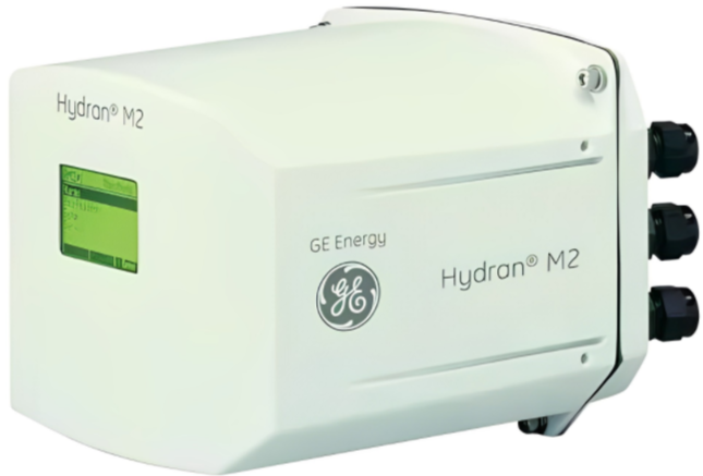
  • GE Hydran* M2 Transformer Gas Monitoring System Installation Guide
  • GE MVME51005E Single Board Computer
  • GE MVME6100 Single-Board Computer
  • GE MVME5500 Single-Board Computer
  • Bristol Babcock Control Wave Micro 396563-07-4 CPU33 240mA @ 3.3VDC
  • GE 151X1235BC01SA01
  • GE 369 Motor Management Relay Instruction Manua
  • GE Grid Solutions 350 Feeder Protection System
  • GE 269Plus Motor Management Relay
  • GE 239 MOTOR PROTECTION RELAY
  • ABB 1TGE106170M4200
  • ABB Procontic T300 Programmable Logic Controller in 35 ZE94 models
  • Control Wave Micro 396603-01-7 Isolated Analog Output Module
  • ABB Procontic T20G Programmable Controller
  • ABB Advant Controllers 400 Series with MOD 300 Software
  • ABB Advant Controller 450 The proven process controlle
  • ABB Advant Controller 450 User’s Guide
  • ABB Panel 800 - PP865 version 5.1
  • ABB Panel 800 - PP836 Hardware and Installation
  • ABB Automatic Transfer Switches
  • ABB Drive contactors Type DA & EHDB
  • ABB EasyLine EL3000 Series Continuous gas analyzers
  • ABB EL3020 EL3040 Continuous Gas Analyzers
  • ABB Advance OptimaAO2000 Series
  • ABB DCS 600 MultiDrive Thyristor Power Converters Series
  • ABB BSD Brushless Servodrives
  • ABB Baldor FlexDrive Servo Drives
  • ABB AC servo motors BSM Series
  • ABB New BSD Series A complete range
  • ABB Advant Controller 110
  • ABB ASTAT Manual AST10_054 Crane motion controller
  • ABB ASTAT A4 EN Manual Crane motion controller.
  • ABB Advant Controller 210
  • ABB Advant Fieldbus 100 User Manual
  • ABB Advant Controller 160
  • ABB Advant Controller 70
  • ABB Advant Controller 31 90 Series Intelligent Decentralized Automation System 90 Series
  • ABB ACV 700 Series Inverter
  • ABB ACV 700 Frequency Converters
  • ABB ACS850-04 drive modules
  • ABB RDCU Drive Control Units
  • ABB ACS800 Converter
  • ABB AC500 Product Series
  • ABB Get more done better with Advant Controller 400 series
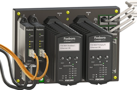
  • FOXBORO FDC280 RH101FQ DCS Modules
  • ABB LDGRB-01 Highly functional controller module
  • Electric tricycle truck, agricultural tricycle, elderly vehicle, warehouse truck
  • GE 8042-CC-85 Carrier extension cable, 0.85m
  • GE 8086-FC-20 20 + 24 pin cables for 8619 (2m)
  • GE 8041-CC-35 Carrier extension cable, 0.35m
  • GE 8085-FC-10 20 + 24 pin cables for 8619 (1m)
  • GE 8034-CC-12 Intrinsically Safe Carrier Extension
  • GE 8082-FC-30 16-pin cable for 8618 (3m)
  • GE 8030-CE-RH Intrinsically Safe Carrier extender, right hand