
K-WANG
+086-15305925923
Service expert in industrial control field!
Product
Article
NameDescriptionContent
Adequate Inventory, Timely Service
pursuit of excellence


Ship control system
Equipment control system
Power monitoring system
Current position:
Brand
Product parameters
- Telephone:+86-15305925923
- contacts:Mr.Wang
- Email:wang@kongjiangauto.com
Description
The user can use the standard Modbus command set to generate a custom set of drivers for his specific
application, or may purchase additional software (for example, OPC with Modbus /TCP protocol) to
reduce or virtually eliminate development tasks.
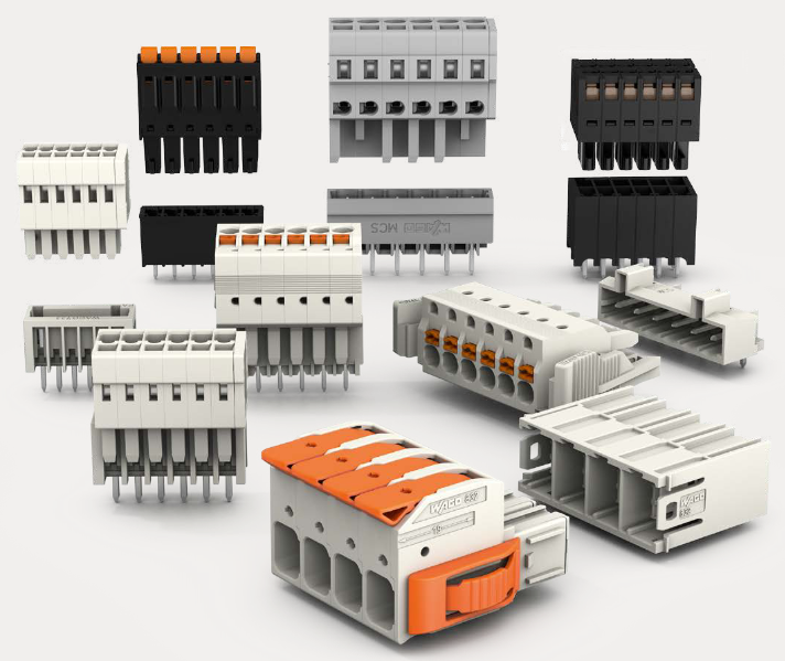
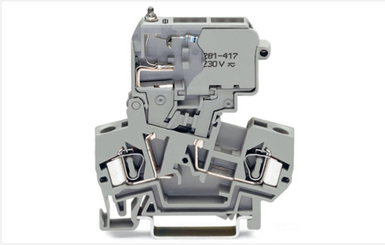
Honeywell High Voltage Terminal Block (Barrier Style) Note 3 900TBR-0101
The user can use the standard Modbus command set to generate a custom set of drivers for his specificapplication, or may purchase additional software (for example, OPC with Modbus /TCP protocol) to
reduce or virtually eliminate development tasks.
HMI software
HMI software available for use with the HC900 Controller includes, but is not necessarily limited to the
following packages.
available from Honeywell
Experion HS Software, which operates under WindowsTM operating software, provides PC-based
supervisory control and data acquisition. This package includes a large selection of standard
operating display templates, which can reduce development time significantly. Experion HS
includes a full graphic display development environment, enabling development of custom
graphics that include animated responses to changing process conditions.
A batch reporting option is available, which includes a standard template for creating batch
reports.
SpecView32 (SpecView Corporation)
Matrikon OPC Server (works with redundant and non-redundant networks)
Other software (available from third-party sources)
The following software, which incorporates Modbus/TCP connectivity, is available from third-party
sources:
The Fix Family (Intellution Incorporated)
Wonderware (Wonderware Corporation)
Citect (CI Technologies)
OPC server/client software (various; available from Kepware and others)
Note: The items in this list are not sold by Honeywell. They have not all been tested and certified by
Honeywell, and are not necessarily recommended or endorsed by Honeywell for any specific use.
Inter-Connection to Other Networks
In many cases, an HC900 Controller application will include a single, free-standing controller that involves
no connections via the Ethernet Open Connectivity network. In other cases, the HC900 Controller will be a
member of a Local Area Network (LAN) as indicated in Figure 19. The HC900 controller LAN may be
very simple, or it may include many devices in a complex and very sophisticated structure. In any case, it
must always be regarded as a single, modular entity that can be protected from intrusion by any other
networking device to which this LAN is connected.
Various types of networking devices that enable selective connection to other networks are available. A
“Router” is commonly used for this purpose.
Routers can examine and “filter” message packets, permitting passage of wanted messages and denying
passage of all others.
The feature that gives the Router its name is it enables translation of IP addresses, which enables networks
with dissimilar network IP addresses to communicate as though they were members of the same network.
This feature is particularly useful when an HC900 Controller LAN is installed under “local addressing
rules”. That is, IP addressing can be assigned without approval of or conflict with world Internet governing
bodies. A default IP address is provided in each HC900 Controller: 192.168.1.254. Later, when connecting
to networks with more stringent addressing requirements, it is necessary only to configure the Router with
address mapping and connect it between the existing LAN and the other existing network.
Connections to other networks vary in purposes and methods; some of these are described below.
E-Mail Communications
The HC900 Controller includes e-mail software that enables communication of Alarms and Events to up to
three Internet addresses. Implementing this feature consists of:
Using the Designer Software to configure:
Alarm Groups and Event Groups
Assignment of specific alarms to priority and e-mail enabling
E-Mail address lists
SMTP mail server IP address
Default gateway must be configured in order to send e-mail. With redundant controllers, two default
gateways need to be configured; one for each of the redundant networks (assuming both are being
used). This will typically be the LAN side IP address of the routers used to connect the controller to
the external network.
Installing and configuring hardware
Note: This data is included for reference. The following items should be implemented by qualified
IT/MIS personnel.
Install and configure a Router to provide isolation and security. (Figure 21) (This should be part of
standard network installation.)
Install and configure internet access to Simple Mail Transport Protocol (SMTP) server. This may
include the location of an existing server on an existing network.
Note: Consult your service provider for availability of access to network, local cable, or DSL in your area.
Serial Ports
(RS-232 and RS-485 for legacy systems and two galvanically isolated RS-485 ports for new
systems)
Overview
Figure 22 – Controller Serial Ports
For Legacy systems, the S1 default setting is RS-232; S2 default setting is RS-485. Each port can be set
to RS-232 or RS-485 (see page 43). For RS-232 cable connections see page 134. For RS-485
connections see page 152.
For new systems, either of two ports S1 and S2 can be configured as RS-485. For SIL applications
communication cable shield connection must be made to IO grounding bar instead of the connector
shield connector.
Ports configurable as ELN (default) or Modbus RTU.
Controller can act as Modbus master or slave through either port.
Controller can be slave to masters such as
On Legacy systems- Operator Interface (1040, 559). Must be on galvanically isolated RS-485 port S2.
Honeywell HC Designer PC software
Third party PC HMI software
Third party Operator Interface
Controller can be master to slaves such as
Any Honeywell Modbus device (e.g., recorders, controllers, flame safety)
Any non-Honeywell Modbus device.
Only one master port at a time; can’t have both serial ports as master ports.
Modbus master ports default to slave ports, ELN protocol when CPUs are in Program mode.
Baud rates to 115,200
Purchase history
| User name | Member Level | Quantity | Specification | Purchase Date |
|---|
Total 0 Record
Related products
Customer Reviews
Satisfaction :
5 Stars
No evaluation information


KONG JIANG


Add: Jimei North Road, Jimei District, Xiamen, Fujian, China
Tell:+86-15305925923


