
K-WANG
+086-15305925923
Service expert in industrial control field!


Product
Article
NameDescriptionContent
Adequate Inventory, Timely Service
pursuit of excellence


Ship control system
Equipment control system
Power monitoring system
Brand
Product parameters
- Telephone:+86-15305925923
- contacts:Mr.Wang
- Email:wang@kongjiangauto.com
Description
Product package
Contents of the product package:
• UNITROL 1000 series AVR
• Special red USB cable that is used to power and to connect with the AVR.
Keep this USB cable in a safe place.
• Red jumper blocks (3 pcs.)
• Quick installation guide and test certificate
Make sure that all of the listed items are in the product package and that there is
no damage to the items.
Hardware overview
Primary parts of the AVR. Refer to the User Manual for more information
ABB UNITROL1020 EXCITATION SYSTEMS
Safety instructions
Read the safety instructions in the User Manual.
WARNING!
• Obey the safety instructions to prevent physical injury or death, or
damage to the equipment.
• Read and make sure that you understand the operating and safety
instructions before you operate the unit.
• If you are not a qualified electrician, do not do electrical installation or
maintenance work.
• Use personal protective equipment, such as, safety shoes and gloves.
Obey these safety precautions before you do work on the system:
1. Clearly identify the work location and equipment.
2. Disconnect all possible voltage sources. Make sure that reconnection is not
possible. Lock out and tag out.
• Open the main disconnecting device of the AVR.
• Disconnect any external power sources from the control circuits before
you do work on the control cables.
• If you have a permanent magnet generator connected to the AVR,
disconnect it from the AVR with a safety switch or by other means.
• After you disconnect the AVR, always wait for 5 minutes to let the
intermediate circuit capacitors discharge before you continue.
• Do not do work on the AVR when the amber warning LED flashes.
3. Protect any other energized parts in the work location against contact.
4. Take special precautions when you are near bare conductors.
5. Measure that the installation is de-energized.
• Use a multimeter with an impedance of at least 1 Mohm.
• Make sure that the voltage between the AVR input power terminals
(PWR L1, PWR L2 and PWR L3) and the grounding terminal (PE) is near
0 V.
• Make sure that the voltage between the AVR output terminals (IE+, IE and ExCap) and the grounding terminal (PE) is close to 0 V.
6. Install temporary grounding as required by the local regulations.
7. Ask for a permit to work from the person in control of the electrical
installation work.
Residual danger areas
WARNING! Do not do work on the AVR when the amber warning LED
flashes.
When the AVR operates,
• The voltage in the power section can be up to 300 V AC and the short-circuit
current is very high.
• The voltage in the control cabinet is more than 50 V.
When the AVR is disconnected from power supplies, the large capacitors in the
AVR hold a charge for some time. Wait for at least 5 minutes for the capacitors
to discharge before you do work on the AVR. An amber warning LED flashes if
the internal voltage is more than 30 V DC.
Warning labels are attached to all of the cubicle doors to warn personnel against
opening the doors during operation.
If the device is built into a larger system, additional warning labels are attached
to the inside of the cubicle doors and to the covers of the power converter
modules.
Consider the residual danger areas when you do work on the excitation system:
• Danger from live equipment inside the excitation system, if the protective
covers are removed.
• Hazardous voltages from the rotor field winding and the secondary side of
the excitation transformer.
• Danger from charged capacitors if a cabinet door is open immediately after
the system stops.
• Danger from main and auxiliary voltages when cubicle doors are open.
Introduction
This document is a quick installation guide for the UNITROL 1010 and
UNITROL 1020 automatic voltage regulator. Make sure that you read and
understand this document before you install or use the product. This document
is meant only as a brief guide to the product. For detailed information on the
product, refer to the User Manual.
Device description
UNITROL 1010 and UNITROL 1020 are automatic voltage regulators (AVR) for
synchronous machines of up to 80 MVA. The AVRs can be used for the excitation
of indirectly excited synchronous machines and motors. The AVRs can also
operate as a reactive power regulators, power factor regulators or field current
regulators.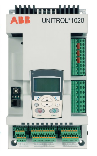
Product package
Contents of the product package:
• UNITROL 1000 series AVR
• Special red USB cable that is used to power and to connect with the AVR.
Keep this USB cable in a safe place.
• Red jumper blocks (3 pcs.)
• Quick installation guide and test certificate
Make sure that all of the listed items are in the product package and that there is
no damage to the items.
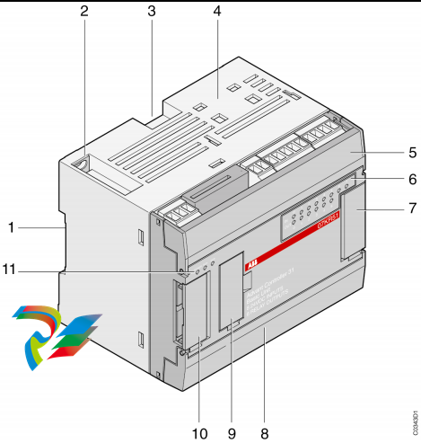
Hardware overview
Primary parts of the AVR. Refer to the User Manual for more information.
Warning and status indicators
Mechanical installation
For detailed information on mechanical installation, refer to the User Manual.
Install the AVR in an indoor area that is dry and dust-free, and that does not
contain volatile gases, acid fumes or similar hazards.
Examine the installation area and refer to technical data to make sure that:
• The maximum ambient temperature is in the permitted range.
• The vibration is limited and within the permitted class.
• The ingress protection and pollution degree are suitable.
• The EMC environment is suitable.
Installation requirements:
• Install the AVR vertically to make sure that cooling operates correctly.
• Free space requirements:
• 50 mm above the AVR
• 20 mm below the AVR
• 10 mm on the left and right sides of the AVR
• Make sure that there is sufficient cooling air flow around the AVR.
• Make sure that other devices do not blow hot air on to the AVR.
• The AVR is designed to be installed with suitable hardware to an installation
plate.
• Make sure that the frame of the AVR is electrically grounded (PE) to the
installation plate with a grounding wire (≥4 mm2) through a mounting hole.
Use toothed washers to get a good electrical ground contact.
Installation procedure:
1. Refer to Dimensions for the mounting hole dimensions.
2. Make the appropriate holes in the installation plate.
3. Attach the AVR to the installation plate with suitable hardware, for example,
M6 screws to a torque of 10 Nm. The mounting holes have a diameter of
6.5 mm.
4. Make sure that there is a good electrical ground connection between the
installation plate and the AVR. The installation plate must be electrically
grounded (PE).
Electrical installation
For detailed information on electrical installation, refer to the User Manual.
CAUTION! Separate control (I/O) cables from the excitation (power and
measurement) cables to avoid electromagnetic interference.
Cable dimension requirements:
Grounding
Connect the AVR to the protective earth at terminal 17 with a 4 mm2 grounding
wire.
Make an additional grounding connection through the mounting holes to the
installation plate (if it is connected to the protective earth) or with a 4 mm2
cable to the protective earth.
Make sure that the grounding connections are as short as possible.
Additional signal ground terminals are provided for the control cables.
Inrush current limitation
The large internal DC capacitor of the AVR can cause a high inrush current
especially with a strong voltage source.
WARNING! To prevent damage to the AVR, make sure that the inrush
current is not more than 200 A for 10 ms.
To prevent damage to the AVR from a high inrush current:
To calculate the inrush current, you can use a capacitor voltage of 0 V at startup.
The external resistor for a 200 V AC input is typically 1.5 Ω.
Power and measurement terminals
1) To reduce wiring, you can connect each phase of the excitation power inputs
(PWR) and auxiliary power supply inputs (AUX) with the included jumpers.
Commissioning
For detailed instructions on commissioning, refer to the User Manual.
Commissioning procedure overview:
1. Make sure that all of the connections are correct and safe.
2. Download the configuration file to the AVR. Make sure that the parameters
are correct.
3. Examine the digital and analog I/Os in standstill.
4. Do tests with the machine:
a) Standstill
• Measure resistance of exciter stator winding.
b) No load condition
• Increase the speed of the machine to nominal.
• Start excitation in Manual mode and increase the manual setpoint until
machine voltage is 50%.
• Use CMT 1000 to verify the AVR measurements and compare them with
other equipment used, such as protection devices.
• Increase the setpoint until the machine voltage is 100% and tune the
AVR with the AVR tuning assistant.
• Do step response tests to examine performance in Manual mode and
Auto mode.
c) Machine connected to grid
• Select AUTO (voltage regulator).
• Increase the AUTO setpoint to verify the polarity of the of IM
measurement. Q must increase.
d) Do step response tests to examine performance in Auto mode and direct
VAR regulator modes.
5. Finalizing commissioning
a) Save the parameters on the AVR and verify the status with CMT 1000.
b) Save backup files for project documentation.
Purchase history
| User name | Member Level | Quantity | Specification | Purchase Date |
|---|
Total 0 Record
Related products
Customer Reviews
Satisfaction :
5 Stars
No evaluation information


- other
- ADLINK
- LTI Drives
- Other Brands
- AMAT
- Iba
- PEPPERL+FUCHS
- Aerotech
- WATLOW
- MAN
- ADVANCED
- Abaco
- YOKOGAWA
- KOLLMORGEN
- MEGGITT
- kong-sberg
- METSO
- Motorola
- NI
- OEMAX
- RELIANCE
- scanlab
- schneider
- uniop
- Vibro-Meter
- Honeywell
- Rolls-Royce
- MOOG
- GE
- B&R
- Woodward
- Yaskawa
- xYCOM
- Siemens
- Emerson
- HIMA
- Bently
- ZYGO
- FOXBORO
- OMACO
- PROSOFT
- ENTERASYS
- TRICONEX
- Parker
- Lenze
- KEBA
- Alstom
- CTI
- ABB
- A-B
172

-
 DEIF PPU 300 controller
 -
 DEIF Delomatic 4 Offshore/Ocean Platform Dedicated Generator Power Management System DM-4
 -
 DEIF Delomatic Modular Generator Set Integrated System
 -
 DEIF AGC-4 Mk II Generator Set Controller
 -
 DEIF AGC-4 diesel generator set integrated controller
 -
 DEIF Multi line 2 Series PPU Unit Power Management (PPM) Operation Manual
 -
 DEIF Multi line 2 V2.4X Installation Manual
 -
 Beckwith M-6280 Digital Capacitor Bank Controller
 -
 Beckwith M-3311 Transformer Protection Relay
 -
 Beckwith M-3311A Transformer Integrated Protection Device
 -
 Beckwith M-3310 Transformer Integrated Protection Device Specification
 -
 Beckwith M-0359 Syncrocloser Check Plus Application Guide for Synchronous Calibration Relay
 -
 Beckwith M-0293A On Load Tap changer Controller Application Guide
 -
 DEIF GPU-3 Synchronous/Asynchronous Generator Integrated Microcomputer Protection Controller
 -
 Installation Instructions for DEIF PPM-3
 -
 Beckwith M-3520 distributed power grid connected comprehensive protection device
 -
 Beckwith M-3430 generator comprehensive protection device
 -
 Beckwith M-2293B adapter panel
 -
 Beckwith M-2001C digital on load voltage regulator controller
 -
 Beckwith M-2001B Digital On Load Voltage Regulating Controller
 -
 Beckwith M-0388/M-0389 synchronous verification relay
 -
 Beckwith M-0193B synchronous closing device
 -
 Beckwith M-0115A Transformer Parallel Balancing Module
 -
 Beckwith M-0067E on load tap changer controller
 -
 Beckwith M-4272 Digital Motor Bus Switching System
 -
 Beckwith M-3311A Transformer Integrated Protection Device
 -
 Beckwith M-3425A Generator Integrated Protection Device Manual
 -
 Basler BE1-27/BE1-59/BE1-27/59 undervoltage/overvoltage relay
 -
 Basler AVC63-12/AVC125-10 excitation voltage regulator
 -
 Basler L301kc Color Three Line Array Camera Operation Manual
 -
 Basler CBS 212A Current Enhanced Excitation System
 -
 Basler BE3-25 synchronous check relay
 -
 Operation Manual for Basler BE1-32R/BE1-32O/U Direction Power Relay
 -
 Basler Electric PRS-250 Veri Sync Synchronous Relay
 -
 Basler Pilot Series Area Array Industrial Camera piA2400-17gc
 -
 Basler BE1-11g comprehensive protection device for generator
 -
 Basler VR63-4C/UL Analog Excitation Voltage Regulator
 -
 Basler BE1-DFPR distribution feeder protection relay
 -
 Basler CBS310/CBS320 current strong excitation system
 -
 Basler UFOV250A/UFOV260A Low Frequency Overvoltage Module
 -
 Basler MVC104/MVC108/MVC232 manual voltage control device
 -
 Basler XR2002/XR2002F PMG excitation regulator
 -
 Basler DECS-400 Digital Excitation Control System
 -
 Basler DGC-2020 Digital Generator Set Controller
 -
 Basler MVC-300 Electronic Manual Excitation Controller
 -
 Basler MVC-104/MVC-108/MVC-232 manual excitation controller
 -
 Basler SSR32-12/SSR63-12/SSR125-12 Static Excitation Voltage Regulator
 -
 Basler SR4A/SR8A Analog Excitation Voltage Regulator
 -
 Basler BE2000E Digital Excitation Voltage Regulator
 -
 Basler DECS-2100 Digital Excitation System
 -
 Basler BE1-851 Overcurrent Protection Device Manual
 -
 Basler APR 63-5 Voltage Regulator
 -
 Basler BE1-FLEX Integrated Protection Control System
 -
 Basler BE1-700V digital voltage protection relay
 -
 Basler BE1-87B high impedance bus differential relay
 -
 Basler BE1-40Q demagnetization relay
 -
 Basler BE1-60 Voltage Balance Relay
 -
 Basler BE1-47N negative sequence voltage phase sequence relay
 -
 Basler BE1-81O/U digital frequency relay
 -
 Basler BE1-11f Feedline Integrated Protection Device Manual
 -
 Basler DECS-250 Digital Excitation Control System
 -
 Basler DECS-100 Digital Excitation Control System
 -
 Basler BE1-BPR Circuit Breaker Protection Relay
 -
 Basler BE1-50/51B-255 overcurrent relay
 -
 Basler BE1-25 synchronous check relay
 -
 Basler BE1-51 microcomputer time limited overcurrent relay
 -
 Basler DECS-300 Digital Excitation Control System
 -
 Mitsubishi MELSEC-F FX series programmable controllers
 -
 Hirschmann cSCALE Mobile Machinery Modular Controller
 -
 Hirschmann OZD Profi G12DU/G12DK/G12DE ATEX1 PROFIBUS Fiber Optic Repeater Manual
 -
 Hirschmann OCTOPUS OS20/OS24 Network Managed IP65/IP67 Industrial Switch Installation Manual
 -
 Hirschmann RS20/RS22/RS30/RS32/RS40 Series Industrial Rail Switch Installation Manual
 -
 Hirschmann EAGLE One Industrial Ethernet Firewall Installation Manual
 -
 Hirschmann MACH102 Series Industrial Switch Installation Manual
 -
 Hirschmann MS20/MS30 Modular Industrial Switch Installation Manual
 -
 Hirschmann BRS20/22/30/32/40/42/50/52 Series BOBCAT Industrial Rail Switch Installation Manual
 -
 Hirschmann RSB20 Basic Series Industrial Rail Switch Installation Manual
 -
 Hirschmann RS20 Basic Series Industrial Ethernet DIN-Rail Switches
 -
 BECKHOFF EP20xx/EP28xx IP67 EtherCAT Box Digital Output Module
 -
 BECKHOFF EL5102 Incremental Encoder Terminal Manual
 -
 BECKHOFF CU8803-000x CP Link4 Launch Box Operation Manual
 -
 Beckhoff CU20xx/CU22xx Industrial Unmanned Switch Manual
 -
 BECKHOFF AMP8000 Distributed Servo System Operation Manual
 -
 BECKHOFF EL2911/EL2911-2200 TwinSAFE Safety Potential Supply Terminal Manual
 -
 BECKHOFF EL600x/EL602x series EtherCAT serial port terminal module
 -
 BECKHOFF CP6700-0001-0050/0060 Integrated Machine Manual
 -
 BECKHOFF CP70xx Series Control Panel Installation and Operation Manual
 -
 BECKHOFF CP29xx Cabinet Mounted Industrial Touch Panel Official Operation Manual
 -
 Beckhoff C6650-0060 Control Cabinet Industrial PC
 -
 Beckhoff BK series K-bus to EtherCAT coupler
 -
 Beckhoff CX20x0 Series Embedded Industrial Control Computer Manual
 -
 Beckhoff CP77xx Series Industrial Panel PC Installation and Operation Manual
 -
 Beckhoff EL41xx Series 16 Bit Analog Output Terminal Manual
 -
 Beckhoff C63xx-0020 series control cabinet industrial PC
 -
 Beckhoff C6920-0060 Control Cabinet Industrial PC
 -
 Beckhoff CU8800-0010 USB transmitter extender (TX)
 -
 Beckhoff AX2000 series digital servo amplifier
 -
 Beckhoff AX8000 Modular Multi Axis Servo System
 -
 Beckhoff CP27xx Embedded Panel PC User Manual
 -
 Beckhoff CP69xx Industrial Embedded Control Panel
 -
 Beckhoff CP60xx Embedded Industrial Control Panel
 -
 Beckhoff CP72xx series panel PC official installation, operation, configuration, maintenance, and troubleshooting
 -
 Installation and Operation of Beckhoff CP78xx Series Control Panel
 -
 Beckhoff CP39xx series industrial touch control panel
 -
 Beckhoff CX8110 Embedded Industrial PC
 -
 Beckhoff CX50x0 series DIN rail embedded industrial PC
 -
 Beckhoff CP62xx series embedded panel PC
 -
 BECKHOFF C6030 Compact Industrial PC
 -
 UniOP ePAD32B/ePAD33B/ePAD33BT Industrial HMI
 -
 UniOP ePAD05&ePAD06 Industrial HMI
 -
 UniOP ePAD03/ePAD04 entry-level HMI
 -
 UniOP CP01R-04 Compact Industrial HMI
 -
UniOP BKDR-16 Industrial Human Machine Interface
-
 Beckwith M-3425A Generator Integrated Protection Relay
 -
 Basler DECS-200 Digital Excitation Control System
 -
 Basler DECS-250 Digital Excitation Control System Manual
 -
 HA-800 series AC servo drive
 -
 JUMO dTRANS p35 Pressure Sensor Operation Manual with IO Link Interface
 -
 KEBA XE 020 RFID Module
 -
 Honeywell SmartLine series transmitters
 -
 Eaton CROUSE-HINDS MTL MA30 RF and Surge Protector Operation Manual
 -
 Beckhoff EL31xx Series 16 Bit EtherCAT Analog Input Terminal Manual
 -
 BECKHOFF AX5000 series EtherCAT servo drive
 -
 BECKHOFF EL30xx Series 12 Bit Analog Input Terminal Manual
 -
 Beckhoff EL70x7 series stepper motor EtherCAT terminal manual
 -
 BECKHOFF CX52x0 Series Embedded Industrial PC Hardware Manual
 -
 BECKHOFF CX9000/CX9010 series embedded controllers
 -
 BECKHOFF AM8000/AM8500 Series Synchronous Servo Motor Operation Manual

K-JIANG

Add: Jimei North Road, Jimei District, Xiamen, Fujian, China
Tell:+86-15305925923