
K-WANG


- Telephone:+86-15305925923
- contacts:Mr.Wang
- Email:wang@kongjiangauto.com
The AC31 system consists of the series 30, 40, 50, and 90. This operating manual describes the series 40 and 50
ABB-AC31-40-Advant Controller
The AC31 system consists of the series 30. 40. 50. and 90. This operating manual describes the series 40 and 50. The AC31 brings accessibility to beginners and experienced automation users alike, for any application with 14 to approximately 1000 inputs / outputs and more, using the same set of basic components. From a compact machine fitted with a few automated functions to large installations spread over hundreds of meter, and even kilometers, the AC31 can fit your requirements. It is therefore possible to realize distributed applications throughout a site, a workshop, or a machine where each component (input / output units, basic unit) is close to the sensors / actuators. The whole setup is connected by a single twisted pair over which all information from the sensors is sent after processing by the basic unit to the actuators via the remote modules. Additional central units configured as slave can also be connected to this CS31 system bus. In case of the series 40 and 50 the following communication interfaces are available, to extend the AC31’s possibilities and integration with the company's other automation systems: MODBUS, ASCII, ARCNET, RCOM, AF100. The developments in this field are continual. Many users on all the continents have realized numerous applications such as: Machine control: - Manufacturing of floor boards - Assembly of electrical contactors - Manufacturing of ceramic products - Metallic pipe welding, etc. Controlling-commanding installations: - Wharf cranes - Water treatment - Ski lifts - Wind power machines, etc. System management: - Climatic anagement - Building power management - Tunnel ventilation - Alarms in hospital environments - Greenhouse lighting / humidity, etc.
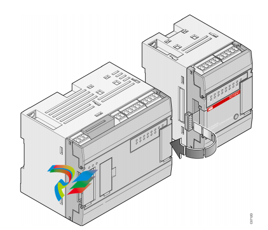
1.2 General set-up rules An ABB AC31 system always includes at least one AC31 basic unit. There are three types of basic units: - The 40 series basic unit, with a local interface for central inputs / outputs extensions - The 50 series basic unit, with a local interface for central inputs / outputs extensions and a CS31 system bus interface for decentralized extensions - The 90 series basic unit, with a CS31 system bus interface for decentralized extensions Each basic unit incorporates a specific number of digital inputs/outputs and in case of the series 90 occasionally analog inputs/outputs. It is possible, depending on the basic unit, to increase the number of inputs / outputs, to add input / output extensions connected directly to the basic units or remote input / output units via the CS31 twisted pair.
A master basic unit can manage up to 31 connection points, such as: - Series 50 remote units with central extension possibilities: a maximum of 6 extension units comprising of e. g. a maximum of 8 analog input channels and 8 analog output channels - Series 30 and 90 remote unit (without central extension possibilities) with analog or digital inputs / outputs - An ABB NCSA-01 variable speed drive interface - A high-speed counter unit - 30. 50 and 90 series basic units as slave with their own user program - Or any other device which supports CS31 communication. Comment: A connection point fitted solely with digital channels occupies 1 connection point. A connection point fitted with digital and analog channels occupies 2 connection points of the available 31. The maximum number of remote analog units depends on the MASTER basic unit: - 50 series: - a maximum of 31 remote analog input units or - a maximum of 31 remote analog output units or - a maximum of 15 central extensible remote units (ICMK 14 ..) with analog input/output extensions + 1 remote analog input/output unit (15 x 2 + 1 = 31) or - a mixed digital/analog configuration within the previous limits - 90 series: - a maximum of 12 remote analog input units or - a maximum of 12 remote analog output units or - a maximum of 12 central extensible remote units with analog extensions or - a mixed digital/analog configuration within the permissible limits
1.3 Power cuts or drops, battery The 40 and 50 series basic units provide an incorporated battery buffer in order to save the necessary information for the next startup should there be a power drop or cut. The buffer battery is an usual in the trade Vanadium Lithium accumulator. It is soldered on a printed-circuit board inside the unit and qualified personnel can exchange it by themselves. The accumulator is 100 % charged after 12 operating hours without interruption. Its lifetime is between 6 and 15 years; it depends on how often and how long the power supply of the unit is switched off. The battery buffer time is 20 days at 25 °C. During that time data (e.g. flags) can be stored with power supply of the unit switched off. The status word %IW 1062.15 (EW 62.15), Bit 3 gives information on the status of the battery (0 corresponds to error, 1 corresponds to OK). Caution: The following operating instructions are to be observed: • Never short-circuit or operate battery with the polarities reversed! They are likely to overheat and explode. Avoid chance short circuiting and therefore do not store batteries in metal containers and do not place them on metallic surfaces. Escaping lithium is health hazard. • Replace battery only with power supply on. Otherwise data may be lost. • Dispose of battery environmentally consciously! To save all or part of the data prior configuration of the basic unit is required (refer to volume 2 - System Technology). If the configuration of the basic unit is absent then all functions and internal data will be reset to 0 after power cut
Basic units 40 Series without CS31- system bus connection Central extensible basic units 07 CR 41. 24 V DC Central extensible basic unit, with 8 isolated inputs 24 V DC and 6 relay outputs 250 V AC / 2 A RS-232 interface for programming or ASCII or MODBUS communication 24 V DC power supply. 1SBP260020R1001 07 CR 41. 120/230 V AC Central extensible basic unit, with 8 isolated inputs 24 V DC and 6 relay outputs 250 V AC / 2 A RS-232 interface for programming or ASCII or MODBUS communication 24 V DC power supply output to power inputs 120 / 230 V AC power supply 1SBP260021R1001 07 CT 41. 24 V DC Central extensible basic unit, with 8 isolated inputs 24 V DC and 6 transistor outputs 24 V DC / 0.5 A RS-232 interface for programming or ASCII or MODBUS communication 24 V DC power supply 1SBP260022R1001 07 CR 42 - 24 V DC Extensible stand-alone basic unit, with 8 isolated inputs 24 V DC and 6 integrated relay outputs 250 V AC / 2 A and 3 analog inputs with 2 voltage inputs +/- 10 V RS-232 interface for programming oder ASCII or MODBUS communication, 24 V DC power supply 1SBP260023R1001 07 CR 42 - 120/230 V AC Extensible stand-alone basic unit, with 8 isolated inputs 24 V DC and 6 integrated relay outputs 250 V AC / 2 A and 3 analog inputs with 2 voltage inputs +/- 10 V RS-232 interface for programming oder ASCII or MODBUS communication, 24 V DC output for supplying the digital inputs 120 / 230 V AC power supply 1SBP260024R1001 07 CT 42 - 24 V DC Extensible stand-alone basic unit, with 8 isolated inputs 24 V DC and 6 integrated transistor outputs 24 V DC / 0.5 A and 3 analog inputs with 2 voltage inputs +/- 10 V RS-232 interface for programming oder ASCII or MODBUS communication, 24 V DC power supply 1SBP260025R1001
| User name | Member Level | Quantity | Specification | Purchase Date |
|---|


- other
- LTI Drives
- ADLINK
- Beckhoff
- Other Brands
- AMAT
- Iba
- PEPPERL+FUCHS
- Aerotech
- WATLOW
- MAN
- ADVANCED
- Abaco
- YOKOGAWA
- KOLLMORGEN
- MEGGITT
- kong-sberg
- METSO
- Motorola
- NI
- OEMAX
- RELIANCE
- scanlab
- schneider
- uniop
- Vibro-Meter
- Honeywell
- Rolls-Royce
- MOOG
- GE
- B&R
- Woodward
- Yaskawa
- xYCOM
- Siemens
- Emerson
- HIMA
- Bently
- ZYGO
- FOXBORO
- OMACO
- PROSOFT
- ENTERASYS
- TRICONEX
- Parker
- Lenze
- KEBA
- Alstom
- CTI
- ABB
- A-B

-
 ADLINK PCI-9112/cPCI-9112 multifunctional acquisition card
 -
 ADLINK PCI-8102 Two Axis Pulse Motion Control Card
 -
 ADLINK PCI-9812/PCI-9810 synchronous 4-channel high-speed acquisition card
 -
 ADLINK PCI-7200/cPCI-7200 high-speed digital I/O board
 -
 ADLINK MXE-1000 series fanless embedded machine
 -
 ADLINK IMB-T10 Mini ITX Industrial Motherboard
 -
 ADLINK HSL Distributed High Speed I/O System
 -
 ADLINK PXI/DAQ/DAQe-2500 series multifunctional analog output DAQ card
 -
 ADLINK PXI/DAQ/DAQe-2200 series multifunctional data acquisition card
 -
 ADLINK ETX-AT ETX Core Computer Module
 -
 ADLINK ACL-7225 ISA 16 channel relay output+16 channel isolated digital input card
 -
 ADLINK DAQ-2000 series synchronous acquisition card
 -
 ADLINK NuPRO-E330 PICMG 1.3 full-length industrial motherboard (SHB)
 -
 ADLINK ACL-8112 series multifunctional ISA acquisition card
 -
 ADLINK USB-2405 24 bit dynamic signal acquisition module
 -
 ADLINK PXIS-3320 15 slot 6U PXI chassis
 -
 ADLINK PCIe GIE7x series acquisition card
 -
 ADLINK PCIe-7856/PCIe-7853 Distributed Motion and IO Main Controller PCIe Acquisition Card
 -
 ADLINK PCI-6308 series isolated analog output board
 -
 ADLINK PCI-7432 Isolated Digital I/O Acquisition Card
 -
 ADLINK NuPRO-E72 PICMG 1.3 Full length Industrial SHB Single Board Computer
 -
 ADLINK MXE-5400 series fanless embedded industrial computer
 -
 ADLINK M-322 Industrial ATX Motherboard
 -
 ADLINK IMB-M43H Industrial ATX Motherboard
 -
 ADLINK IMB-M42H Industrial ATX Motherboard
 -
 ADLINK i915GV-INA ATX motherboard
 -
 ADLINK ETX-NR667 Embedded ETX Standard Computer Module
 -
 ADLINK ETX-BT (PATA to SATA version) User Manual
 -
 ADLINK CM1-BT1 PC/104 Single Board Computer
 -
![ADLINK cPCI-8217 [R] 3U CompactPCI VGA/LCD Display Module](https://aosspic10001.websiteonline.cn/hkw632bc8/image/image_aJXQRn.png) ADLINK cPCI-8217 [R] 3U CompactPCI VGA/LCD Display Module
ADLINK cPCI-8217 [R] 3U CompactPCI VGA/LCD Display Module -
 ADLINK AmITX-SL-G Mini ITX Embedded Motherboard
 -
 ADLINK AmITX-AL-I ultra-thin Mini ITX industrial motherboard
 -
 ADLINK NuPRO-E315 Full length PICMG 1.3 Industrial SHB Single Board Computer
 -
 ADLINK NuPRO-842 Full length PICMG 1.0 PCI/ISA Industrial Single Board Computer
 -
 ADLINK NuPRO-900A PICMG 1.2 ePCI-X Dual Xeon Industrial System Motherboard (SHB)
 -
 ADLINK cPCI-6910 series 6U CompactPCI single board computer
 -
 ADLINK cPCI-6860A 6U CompactPCI dual core single board computer with cPCI-R6860A rear adapter board
 -
 ADLINK cPCI-8168 6U CompactPCI Eight Axis Motion Control Card
 -
 ADLINK NuPRO-E340 PICMG 1.3 Industrial SHB motherboard
 -
 ADLINK NuPRO-A40H Full length PICMG1.0 Industrial Single Board Computer (SBC)
 -
 ADLINK NuPRO-852 Full length PICMG1.0 Industrial Single Board Computer
 -
 ADLINK NuPRO-841 Full length Industrial SBC
 -
 ADLINK NuPRO-590/591/592 series Socket7 full-length industrial SBC
 -
 ADLINK MXE-5500 series fanless embedded industrial computer
 -
 ADLINK MXE-200/200i Fanless Embedded Machine
 -
 ADLINK cPCI-6770 series CompactPCI CPU board
 -
 ADLINK NuPRO-A301 standard PICMG 1.0 full-length industrial SBC single board computer
 -
 ADLINK NuPRO-965 PICMG 1.3 SHB Express Full length Industrial Motherboard
 -
 ADLINK NuPRO-935A Full length PICMG1.0 Industrial Single Board Computer
 -
 ADLINK NuPRO-865 Full length Single Board Computer
 -
 ADLINK NuPRO-840 DV/LV Full Length PICMG Industrial Single Board Computer
 -
 ADLINK NuPRO-770 series full-length industrial single board computer
 -
 ADLINK NuPRO-595 series half length Socket 7 industrial motherboard
 -
 ADLINK cPCI-6840 series 6U CompactPCI single board computer
 -
 Foxboro 43AP series pneumatic indicator controller (PSS 3-1B3 A)
 -
 ADLINK cPCI-3720 Series 3U Low Power CompactPCI Single Board Computer
 -
 ADLINK NuPRO-E47, PICMG 1.3 full-length industrial SHB system motherboard
 -
 ADLINK NuPRO-E43 PICMG 1.3 full-length system motherboard
 -
 ADLINK NuPRO-780 series full-length industrial CPU board
 -
 ADLINK cPCI-6965 series 6U CPCI single board computer
 -
 ADLINK USB/LPCI/LPCIe-3488A GPIB interface card
 -
 Rittal SK 3241.700 Blue e+Fan Filter Unit
 -
 ADLINK cPCI-8168 6U CompactPCI 8-Axis Motion Control Card
 -
 ADLINK PCIe PXIe-8638 PCIe to PXIe Bus Expansion Kit
 -
 ADLINK PCIe GIE7x series acquisition card
 -
 ADLINK PCIe-7396 96 96 channel TTL digital IO card
 -
 ADLINK PCI/MPC/PXI-8164 Three in One Motion Control Card
 -
 ADLINK PCI-8154 Four Axis Pulse Motion Control Card
 -
 ADLINK PCI-8134 Four Axis Servo/Stepper Motion Control Card
 -
 ADLINK NuPRO-E42 PICMG1.3 full-length SHB motherboard
 -
 ADLINK MXC-6600 series high-performance fanless extended industrial computer
 -
 ADLINK MXC-6000 series embedded industrial control computer
 -
 ADLINK MXC-2300 series fanless expandable embedded industrial computer
 -
 ADLINK MCM-204 Independent Ethernet DAQ User Manual
 -
 ADLINK MCM-100/102 Edge IoT Platform for Machine Condition Monitoring User’s Manual
 -
 ADLINK MXC-6400 series sixth generation Core Fanless Scalable Industrial Control Computer
 -
 ADLINK Matrix Full Series Fanless Embedded Industrial Control Computers
 -
 ADLINK GIE64+4-channel PoE Gigabit Vision Capture Card
 -
 Honeywell UMS Security System Troubleshooting Guide
 -
 Honeywell Expert Series-C I/O Module
 -
 ADLINK EOS-1200 Embedded Vision Host
 -
 ADLINK DLAP-5200 series high-performance fanless AI industrial computer
 -
 ADLINK DLAP-4000 series embedded industrial control computer
 -
 ADLINK Matrix MXC-2000 Series Fanless Industrial Control Computer Specification
 -
 ADLINK DAQ -/DAQE -/PXI-2000 Series Multi functional Synchronous Acquisition Card
 -
 ADLINK cPCI-6520 6U CompactPCI Single Board Computer
 -
 ADLINK CM1-86DX3 PC/104 Single Board Computer
 -
 Honeywell DC1000 series PID temperature controller
 -
 ALSTOM MiCOM C264 Modular Substation Controller
 -
 EMERSON AMS 2140 Mechanical Health Analyzer
 -
 ADLINK NuPRO-E320 PICMG1.3 Full length Industrial Motherboard
 -
 ADLINK NuPRO-800 Series Full length Industrial SBC User Manual
 -
 ADLINK NuPRO-598 Industrial Single Board Computer
 -
 ADLINK MXC-6300 Fanless Embedded Industrial Control Computer
 -
 ADLINK Express-BASE7 User Manual
 -
 ADLINK DLAP-211 Series Fanless Edge AI Platform Specification Manual
 -
 ADLINK PCI/LPCI/LPCIe/cPCI-723X series 32 channel isolated digital I/O card
 -
 ADLINK cPCI-6965 series 6U CompactPCI single board computer
 -
 ADLINK NuDAQ 7200 series high-speed digital I/O board
 -
 Linghua ADLINK DLAP Deep Learning Acceleration Platform Product Manual
 -
 DEIF TCM-2 thyristor control module
 -
 Installation Manual for DEIF MVR-200 Series Medium Voltage Protection Device
 -
 DEIF MDR-2 multifunctional differential relay
 -
 DEIF AOM-1 Analog Output Module
 -
 DEIF AGI 400 series industrial/marine touch screen
 -
 Installation Manual for DEIF BRW-1 Marine Wing Bridge Instrument
 -
 DEIF AGC200 Quick Start Guide
 -
 DEIF AGC Multi line 2 Generator Set ControllerProduct basic information
 -
 ABB SPA-ZC 400 Ethernet Gateway Installation and Debugging Manual
 -
 ABB REM 543/545 motor generator protection device
 -
 DEIF PPU 300 controller
 -
 DEIF Delomatic 4 Offshore/Ocean Platform Dedicated Generator Power Management System DM-4
 -
 DEIF Delomatic Modular Generator Set Integrated System
 -
 DEIF AGC-4 Mk II Generator Set Controller
 -
 DEIF AGC-4 diesel generator set integrated controller
 -
 DEIF Multi line 2 Series PPU Unit Power Management (PPM) Operation Manual
 -
 DEIF Multi line 2 V2.4X Installation Manual
 -
 Beckwith M-6280 Digital Capacitor Bank Controller
 -
 Beckwith M-3311 Transformer Protection Relay
 -
 Beckwith M-3311A Transformer Integrated Protection Device
 -
 Beckwith M-3310 Transformer Integrated Protection Device Specification
 -
 Beckwith M-0359 Syncrocloser Check Plus Application Guide for Synchronous Calibration Relay
 -
 Beckwith M-0293A On Load Tap changer Controller Application Guide
 -
 DEIF GPU-3 Synchronous/Asynchronous Generator Integrated Microcomputer Protection Controller
 -
 Installation Instructions for DEIF PPM-3
 -
 Beckwith M-3520 distributed power grid connected comprehensive protection device
 -
 Beckwith M-3430 generator comprehensive protection device
 -
 Beckwith M-2293B adapter panel

K-JIANG

Add: Jimei North Road, Jimei District, Xiamen, Fujian, China
Tell:+86-15305925923